Posts Tagged ‘WSPR’
 Nothing but whispers
In the last few days several people have posted in their blogs or in forums that conditions on 10m have been great. Either I have been listening at the wrong times or this QTH is as bad on the higher HF bands as it is on VHF. When I have tuned across the 10m band I have found only one or two signals strong enough to be heard above the S4 noise level I now have on this band and none loud enough to work.
It’s probably my QTH. Last year when Olga was away in Ukraine I operated from the car with my QRP K2 and an MP-1 antenna on a mag mount and from just a few miles away but overlooking the coast I worked DX on 15 and 17m that I had never heard from home. Unfortunately going mobile is no longer an option as I am not allowed to drive due to my illness.
Something must be working right though. Most of the day I have been running WSPR on 10m with 5 watts to the dipole and my signal was spotted on 5 continents. It’s good, but it isn’t the same as having an actual conversation. You can see why my interest these days is turning more towards things like EchoLink.
QRPp WSPRing
 |
| How to pass the time while WSPRing |
Leading up to last weekend the sunspots were at an all time high along with the solar flux......it seemed that the radio god's were smiling on us again!! I turned on the K3 on the weekend and it was kinda a down, it seemed that 20 meters may not had been as hot as I hoped it to be. I then turned to WSPR and thought I would give that a go on 20 meters as well. I wanted to put this solar hot spot to the test.....so instead of setting the K3 on the standard 3 watts output I dropped it down to 500mw's. I gave it a go and was surprised at the good
 |
| Dipole at 500mw's |
actual power out on the antenna is??? Well according to VK1OD.NET who offers a great RF transmission line loss calculator I could get a good idea. So I punched in all the necessary information I was told my setup is about 95.23% efficient. Well I punched the numbers into Google and it came up with 95.23% of (500 milliwatts) = 0.47615 watts. So I was pumping out 476mw's into my European contacts on WSPR.
 |
| H900 on RX and dipole on TX 500mw's |
If you are a frequent user of WSPR then one knows it basiclly can run on it's own collecting data...so what does the ham do during this down time..........start building his KAT100 antenna tuner of coarse!!
 |
| Dipole on RX dipole on TX 200mw's |
 |
| H900 on RX dipole on TX 200mw's |
VK on a whip antenna
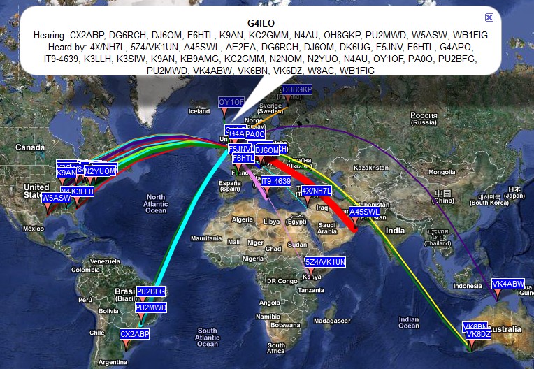
The amazing power of the WSPR mode to enable weak signals to be received over long distances was demonstrated conclusively when my 2 watt signals, transmitted into a 1.3m long telescopic whip antenna from inside the G4ILO shack,were received in Australia and the USA, not once but several times with SNR reports of up to -19dB.
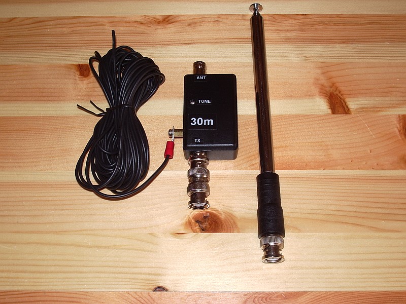
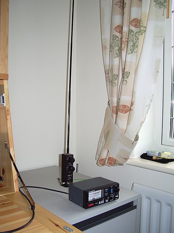
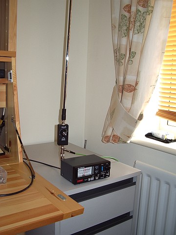
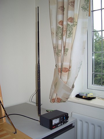
These spots were not achieved using a hand held radio as they occurred early in the morning when I was asleep. But they were made using a home made portable 30m whip antenna that I designed to be used with the VCXO-AXE portable WSPR transmitter I recently built. Here is a picture of the antenna taken during the tests.
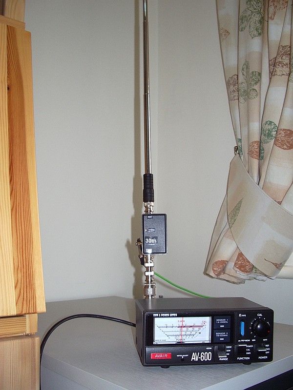
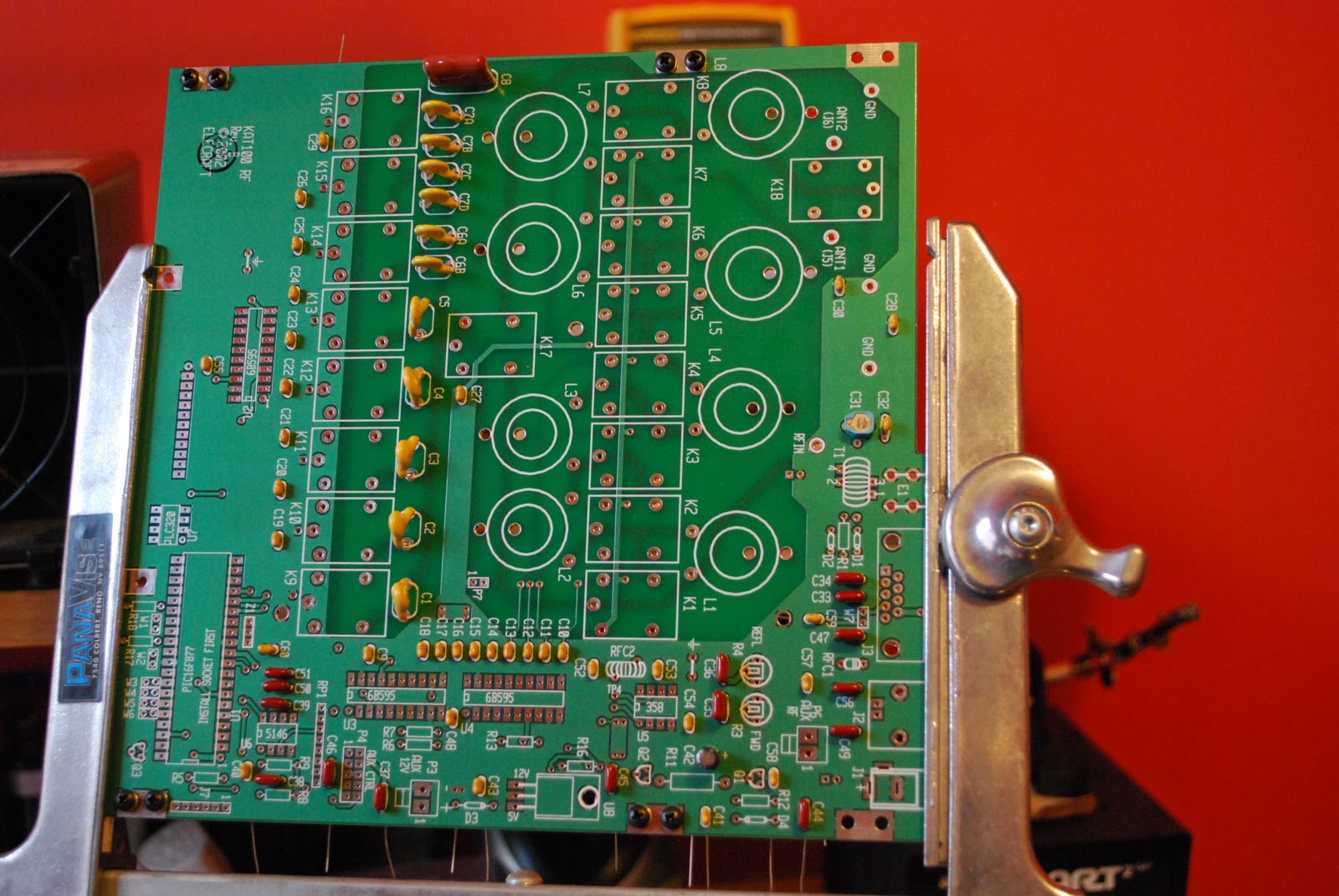
The antenna consists of an L-match mounted in a small plastic project box, with BNC sockets for the transmitter and the whip antenna.
The constructional details can be gleaned from this internal view here. Click the image to see a much larger version.
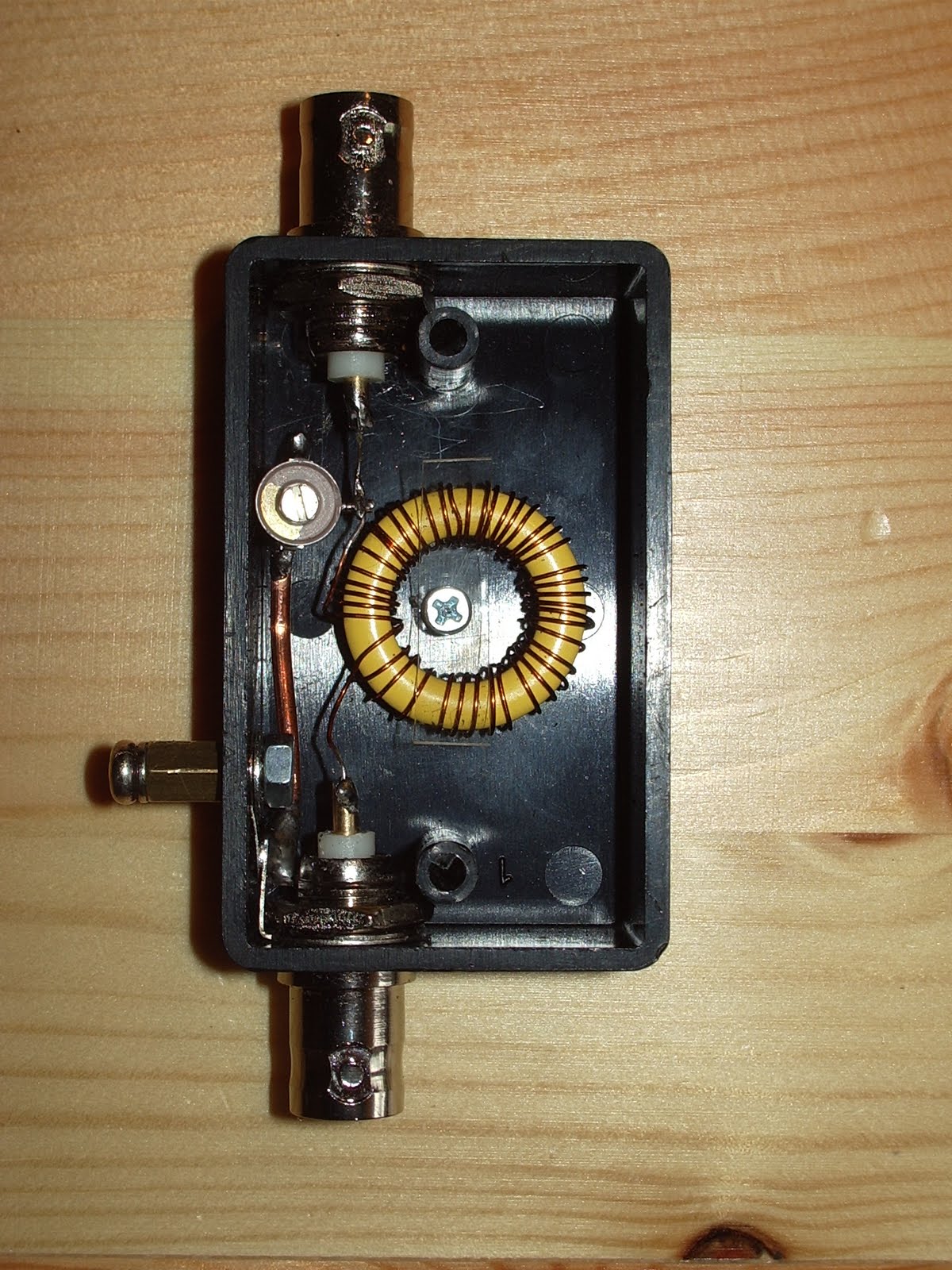
The loading coil consists of about 46 turns of 28SWG wire on a T80-6 toroid. The matching capacitor is a 4 – 40pF trimmer. The number of turns was determined empirically (i.e. using trial and error) so don’t ask me for details of how to make one for other bands. There may be formulas for calculating things like that but I don’t know them.
It would have been difficult to make this antenna without an antenna analyzer like my RigExpert AA-200 which displays the SWR across a range of frequencies graphically. With my first attempt at the inductor it was possible to obtain an SWR null at 10.140MHz but it was rather a broad dip and the minimum was around 3:1. However at lower frequencies I saw that I was able to obtain a much deeper, sharper null. This made it clear that what I needed to do was remove some turns until the deep, sharp null was at the frequency I wanted. A deep null indicates higher Q and therefore better efficiency.
You can see the SWR curve of the final version below.

Note, however, that this was taken inside the shack in the test position where reflections spoiled the SWR and broadened the dip. When measured out of doors the SWR curve dipped deeper and was narrower as long as I stood clear of the antenna. (It was interesting to note how the SWR was affected even if I was a metre away from the telescopic whip. This suggests efficiency would be adversely affected when used in true hand held fashion.)
A good ground or quarter wave counterpoise wire is needed with this antenna. The resonant frequency is affected by the ground system used as well as the length of the whip and the position of the trimmer. If you don’t want to take an antenna analyzer to the field to check and tune the antenna before operation you should use the same counterpoise. So it would be advisable to pair the counterpoise with the antenna.
Further tests would be useful to determine the extent to which a good match is reproducible in different locations using the same whip length and counterpoise without retuning.
In case retuning is needed I added an access hole for the tuning trimmer. The resonant frequency can also be changed (increased) by shortening the telescopic whip a section or two.
This has been an interesting project. As a result of it I now have a completely portable, pocketable, battery powered system capable of sending a radio signal half way round the world, and I have developed a useful monoband 30m antenna.
The WSPR Boss
I ordered a GymBoss workout timer – not as a keep-fit aid but as a timer controller for the VCXO-AXE WSPR transmitter.
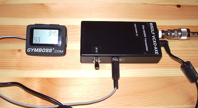
W5OLF doesn’t provide a lot of detail on how to modify the GymBoss but it isn’t difficult – especially if you don’t have fuzzy vision, shaky hands and fingers the size of Cumberland sausages. As I have all of those things I experienced an initial panic as I thought I was more likely to break the GymBoss than successfully modify it. Consequently I neglected to take any pictures of the process as I just wanted to get the job done without additional distractions.
Two screws secure the base of the GymBoss. Lift this away carefully as it is secured to the PCB by two short, flimsy and not particularly well soldered wires from the battery compartment. Once the base is clear you can remove two more smaller screws which hold the PCB to the front panel. At this point the pushbuttons will fall out – hopefully you will have made a note of exactly how they were installed so you can put it back together without too much difficulty.
The LCD display rests on the back of the PCB and can be hinged clear to reveal the bottom of the board. The beeper which has to be removed has two connections. The easiest way to remove it I found was just to grasp it between finger and thumb whilst applying the soldering iron to each of the two pins in turn, pushing the board away a bit at a time with another finger until it was clear.
I then soldered a thin screened cable to the two holes that had been used by the beeper. Using my ohmmeter I identified one hole that was at ground potential, so the braid was soldered to that one. I made a small hole in the case near to the “reboot” switch hole to allow the cable to exit. Then I carefully reassembled the GymBoss.
I attached the beeper to the end of the screened cable to check that the GymBoss still worked. To my relief, it did. I then attached a plug to match up with the socket I had already installed for P2 when I built the VCXO-AXE. The braid goes to the ground connection and the beeper signal to the Start pin. I then checked the transmitter with my power meter / dummy load to ensure that the GymBoss was turning it on at the interval I had chosen.
The timer works well and has maintained adequate accuracy for the 12 hours or so it has been running so far. It will start up to 99 transmit cycles at any interval you specify, so you can’t have it run indefinitely if you leave it unattended.
As of right now I am running a transmit cycle every 8 minutes using 2 watts into a home-made loaded whip antenna inside the shack using the central heating system as a ground. This has received plenty of spots from Europe and a few overnight from W3HH in the USA which I would not have been able to obtain if I had to key the transmitter manually.
Although manual keying is simple and fine for occasional use, I’m in no doubt that the timer makes the WCXO-AXE much more useful.
Get the drift
Don’t you hate it when you build a project, it works, then you put it into a case and find that it is no longer working as well as it was?
I built the VCXO-AXE 30m WSPR tramsmitter and it worked perfectly. I then put it in a nice case and began testing it with various portable antennas. At the start I received several spots of my transmissions but after a while the spots became few and far between until hours would pass without any report of my signal.
At first I thought this was due to poor conditions or the fact that the antennas I was testing were inefficient. Eventually I investigated by putting the TX on a dummy load and listening for it with my K3. I found that although I had initially set the VCXO-AXE up to transmit 40Hz above the bottom of the 200Hz wide WSPR band, the frequency had drifted low so that my transmission was now right on the bottom edge and possibly below it on many receivers since I couldn’t guarantee my K3 readout was dead accurate.
It was easy enough to set the transmit frequency back to what I wanted it to be. But I still didn’t receive any spots of my signals.
I looked a bit closer and noticed that although my signal started off as a horizontal line for about the first two-thirds of the transmit cycle, the last third curved down a little. The WSPR software was reporting a drift of -3Hz, which was typically what I had been receiving from those stations that had spotted me. There is a thread in the forum section of the WSPR website which suggests that few signals which drift more than 3Hz are reported. So it seemed probable that drift of my signal was preventing it from being spotted.
Before I put the transmitter into a box the frequency had been perfectly stable after the initial warm-up period. So it was obvious what the trouble was. I drilled a small grid of ventilation holes in the back of the case just above the PA FET and attempted to increase the thermal inertia of the VCXO chip by placing a blob of Blu-Tack over the top of it. This made not the slightest difference. I was still getting -3Hz drift reported on the decodes of my transmissions.
After further investigation I found that the worst heat generating component was in fact the 5V voltage regulator, which also happens to be fairly close to the VCXO chip. So I drilled a further set of holes above that. I also fabricated a heat shield from a piece of cardboard sandwiched between the PCB and the back of the case with Blu-Tack to try to induce most of the heat to go out through the holes instead of heading in the direction of the oscillator. This did make an improvement. I’m now mostly seeing reports of -1Hz drift or even none at all. And I’m getting a lot more spots of my WSPR transmissions!
A WSPR Handy-Walkie
The VCXO-AXE WSPR transmitter has now been put into a plastic project box and lettered with Dymo tape. I think it looks rather smart even if I say so myself.
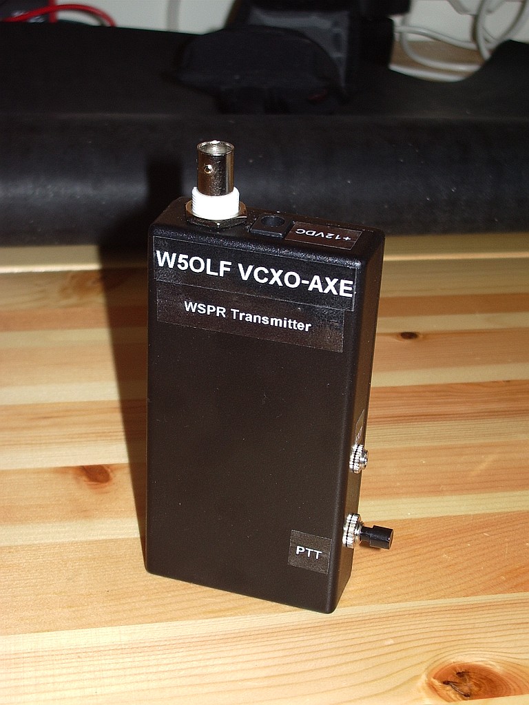
It did think about building it into a box that contained the batteries as well but that would have made it larger and prevent the batteries being used for something else. Plus I already had a box that fit the transmitter by itself. So what I now have is a pocket WSPR handy. Imagine going to the park or the beach or a hilltop and sending a signal that could be received half way round the world using a battery powered radio you can hold in your hand. How cool would that be?
Unfortunately the charger that charged my 10 AA cell NiMH QRP battery pack decided to fail and I’d exhausted the batteries during my initial tests so I couldn’t try portable operation unless I first spent a day charging the cells up 4 at a time. So I decided to see how far my 30m WSPR signals would get using a selection of hand held QRP antennas with the rig running off the bench power supply in the shack. As most of the antennas are equipped with right-angle PL-259 connectors for attachment to the back of an FT-817 I attached them to the back of my SWR/power meter with a short patch lead connecting it to the VCXO-AXE. For an RF ground I used the nearby central heating radiator.
The Wonder Wand L-Whip produced several spots from as far afield as Italy during the morning.
The Miracle Ducker with 1.4m telescopic whip was somewhat less successful, though as I tested it at a different time of day it would perhaps be wrong to draw any conclusion from that. I used the MD with the radiator counterpoise. Although it would give a reasonable SWR with no counterpoise at all the current drawn by the VCXO-AXE TX increased from around 300mA to 400mA which made me think the PA might not be happy so I decided not to test it like that.
The most surprising result came from the ATX Walkabout antenna. For those unfamiliar with it, this is a small QRP antenna with a 1.4m telescopic whip and a base loading coil that is tapped for the 80m, 40m, 20m, 15m, 10m and 6m bands. To use the WARC bands with this antenna you have to use the tap for the next lower band and then obtain resonance by shortening the whip. On 30m the whip length is only about 40cm! The length of coil that is in use (not shorted out) is about 15cm.
So this antenna when used on the 30m band is effectively less than 2 feet long! Despite that it produced several spots at quite respectable SNR levels. The SWR using the radiator ground was a rather poor 3:1. I suspect that this, and overall efficiency, would have been improved if I had used a quarter wave counterpoise, but I didn’t have 7.5m of wire handy and it would not have been practical to deploy it inside the shack in any case.
Obviously with a good antenna you will get stronger reports, be heard further afield and get more spots. But from the results of these tests it appears that even with a compromise hand held antenna (and a counterpoise for grounding) some interesting results could be possible using this little WSPR transmitter. Great fun!
The Land Down Under–Finally
I’m amazed that nearly four years into the wonderful hobby, I still find myself getting ‘as giddy as a schoolboy’ with some accomplishments in the amateur radio hobby. Of course, this is just a reminder how how truly awesome this hobby of ours really is.

My first QSO as a licensed ham was made on 18 August 2008 on a local 2m repeater with WA0DFW. I had only had my license a few days, but had spent time listening on the local repeater. I took the advice of Gordon West and clearly stated, This is KD0BIK looking to make my first contact as a licensed ham. Mo came back to me and we had a nice QSO. Within about 5 minutes the rest of the afternoon repeater crowd had joined in and I was ‘smack dab’ in the middle of my first roundtable. Mo was kind enough to invite me to send him a QSL card, which he would reciprocate to mark the occasion of my first ham radio QSO. By the way, I made my first HF contact a little over a month later during a 10m DX contest. The station was ZW5B (a contest station) in Brazil.
If you have followed my blog over the years and also listen to my podcast, The Practical Amateur Radio Podcast you know I live in an HOA restricted neighborhood. My restrictions state no outside antennas other than satellite and small digital TV antennas. The policies also state permission must be received from the architectural review committee so they can approve placement of these antenna types. So how do I operate HF?
I think the answer to that question is probably best answered in a future blog posting, so please stay tuned and I’ll add that to my long list of items to blog about. I’ll just add that my antenna setup is as stealth as I can get it and do most of my HF operations on a 20m hamstick dipole. This hamstick dipole has gained me many DX stations in my logbook. I also have a Hustler 6BTV vertical which I use for 10, 30, 40 and 80m. The 20m hamstick dipole really outperforms 20m from the vertical. But I’ll save that discussion for another time.
I grew bored with what was on the “boob tube” (TV Set) and decided to go down to the shack to see what I could conjure up on the HF bands. I had been working JT65-HF earlier in the evening and decided to see what was biting. Within a half hour I had answered about four CQ’s and decided I should probably turn the radios off and head upstairs to read and study for the extra class license I’m working on. My self-control just doesn’t allow me to study in the ham shack. Before I know it, I’ve turned on a radio or two and have Twitter, Facebook and Google+ all up and I’ve wasted time I could/should be using to study. But before I shut down I decided I would answer one more stations CQ. After all, why work just four stations when you can work five?
Much to my surprise the next station I saw calling CQ on JT65-HF was a VK station. Without hesitation, I double-clicked on his entry and hit the “Answer CQ” button. A few seconds later my Yaesu FT-897D started the 50 second transmit cycle. This was one of the longest 50 seconds of my life and of course I would need to wait another minute to learn if the VK station copied my signal. While I’ve worked many DX stations before on SSB, PSK, RTTY…this would be the first DX station using JT65-HF. Fingers crossed, the next thing I would see would be his report to me and after his transmit cycle I wasn’t disappointed. He had copied me and gave me a signal report of –20. The complete JT65-HF QSO was complete a few minutes later after I sent his report (-16) and the final 73. VK3BM became my first Australian JT65-HF contact and I was very pleased.
It wasn’t until this morning I realized the JT65-HF contact I had made with VK3BM was actually much more impressive. VK3BM became not only my first JT65-HF contact in Australia, but my first Australian DX contact and of course my furthest contact ever made from my home QTH station at a distance of 8,760 miles. I’ve been as ‘giddy as a schoolboy’ ever since realizing this.
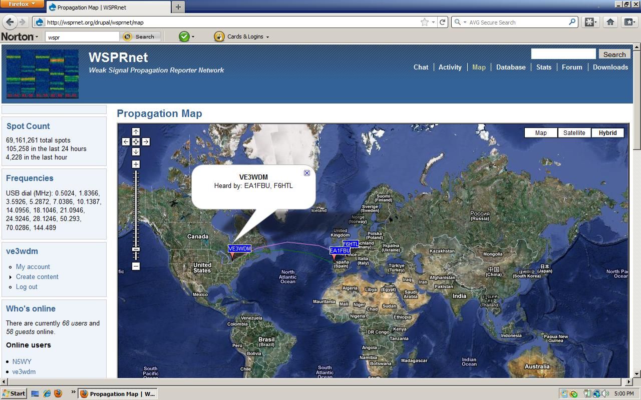
While I know my station has been heard many times in and around Australia from using WSPR (this was also exciting the first time), I’ve never actually managed to have a true two-way contact until now. While JT65-HF may not be a voice mode and it doesn’t provide for “rag chewing” QSO’s, it does provide an exchange of callsigns, locators, and signal reports all in real-time with an operator on both ends.
Remember, you don’t need a tall tower and high priced amplifiers to work DX. Also, just because someone says “no you can’t have an antenna” doesn’t mean you still can’t get on the air and work DX stations like I do. You just have to be smarter and have a lot of patience. Yes you can do it.
So….what’s stopping you?
Until next time….
73 de KD0BIK


