Author Archive
 Seek and you shall find.
 September 17th, 2026 |
  Author:

If you’ve been visiting my blog, you might have noticed that my sidebar "Blogs I follow" list has stopped updating with the most recent posts. I have been doing some reading and checking with other Blogger who use Blogger and they has the same issue. It seems to be an issue at Bloggers end and they are very slow to fix it.
I was getting very tired of seeing the blogs I follow just sit there without updating. It can be frustrating for those who visit my blog and like to read the blogs that I also follow.
I finally took some time behind the scenes to revamp my sidebar widget! It turns out it is possible to fix those stuck Blogger posts I follow and get fresh feeds flowing again using a few layout tweaks. Along side AI's help I was able to use the blogger HTML/JAVA widget to assemble some HTML coding that gets the job done.
Now, whenever you visit, you can check out the sidebar to see the latest posts and active updates from the blogs I follow. It may not be as fancy as the Blogger widget but its now updating. Once blogger fixes the issue I can go back to the Blogger widget for following blogs as at this time it is just turned off.
“Jim I’m only a doctor”

When I opened up HamClock today I was reminded that September 8th is Star Trek day. I had the USS Enterprise NCC 1701 slowly moving across my screen on HamClock. Hats off to those at Open HamClock Back-end for making this happen.
Time for antenna work.
 |
| Before the DX Engineering radial plate |
The vertical antenna I have is the Hustler 4BTV, which gives me 10–40m, and I am very happy with its performance. One shortfall for me is the method this antenna uses to fasten the ground radials. At the base of the antenna, there are two stainless steel nuts and bolts. All the radials are bunched together and fastened to one of the two nuts and bolts. The antenna works just fine this way, but for me, I wanted something better.
In my search, I found the DX Engineering radial plate. The plate is stainless steel, and it comes
with 20 nuts, bolts, lock washers, and washers. If you are securing the
plate to a metal post, as I was, you need to order a clamp as well. When
the plate arrived, I was very impressed with the detail and its weight.
It is a very high-quality product. 
Radials removed
The first order of business was to take the Hustler 4BTV down and then remove the antenna mounting bracket. This would allow me to place the new radial plate over the mounting post and secure it. Once that was done, I then reattached the Hustler 4BTV mounting bracket to the mounting post as well. The antenna mounting bracket and the new radial plate connect via the metal mounting post.
As this mounting post is a
fence post and can become corroded from exposure to the weather, I
installed two jumpers from the antenna mounting bracket to the new
radial plate. I then connected the ground rod cable to the plate. From
there, it was simply a matter of securing all the radials to the new
plate. 
New plate and bracket installed
While I was doing this, I decided to take the cover off the Balun Designs 1:1 balun to see how it looked. As you can see from the picture in my post, it looks brand new.
 |
| 1:1 Balun |
 |
| Radials installed |
 |
New jumpers installed
|
Part 2 of….. Antenna solve one problem to only create another.
 |
| My new SWR on 15M |

 |
| Issue found. |
Antenna…solve one problem only to create another.
The antenna I have is the Hustler 4BTV, and I have owned it for about four years. I had been noticing that after a couple of days of rain, the SWR on 15 meters would increase.As the weather warmed up, the problem disappeared. My suspicion was that water was making its way into the 15-meter trap and causing the SWR issues.
I waited for a forecast of a few nice, dry days before taking the antenna down for inspection. The first thing I noticed was that I had accidentally covered the drainage slots at the bottom of each trap with electrical tape. If water was getting into the traps, those slots were intended to let it drain out. My first course of action was to remove the tape from all three traps.
 |
| Tape removed from drainage slots |
I started with the 20-meter trap, then moved on to the troublesome 15-meter trap. As soon as I removed the tape from the 15-meter trap, a small amount of water drained out. I then removed the tape from the 10-meter trap, and like the 20-meter trap, no water came out.
Each trap has a plastic cap at the top that helps keep water out while also insulating the trap tube from the center antenna element. This seemed like the most likely place for water to enter the trap, so I decided to disassemble the 15m trap for a closer inspection.
Before taking anything apart, I carefully marked the position of the tubing so I could reassemble it in nearly the exact same location. My hope was that this would keep the antenna's SWR very close to where they had been. See above drainage pic for position marking in red.
After removing the 15-meter trap from the antenna, I took off the plastic cap and inspected it closely. I couldn't find any visible damage, but I know that water can find its way through even the smallest of gaps. That alone could have been enough to cause the SWR problems I was seeing.
 |
| Outer tubing showing water drops |
With the cap removed, I looked inside the trap and found several small water droplets. I then removed the outer trap tubing so I could inspect the trap winding and all of the electrical connections.
Fortunately, everything inside the trap was in excellent condition. The winding and all of the connections looked perfect, which reinforced my belief that moisture—not corrosion or a failed connection—was the source of the problem.
After thoroughly drying all of the parts, I noticed the original bead of silicone that had been applied during manufacturing. When I first tuned the antenna after purchasing it, I had to slide the 15-meter trap's outer tube to adjust its resonant frequency. My guess is that this movement disturbed the original silicone seal. If so, it was probably only a matter of time before water found its way inside. I was actually surprised it took four years for the problem to appear.
 |
| 15m trap condition |
When I reassembled the 15-meter trap, I applied non-acetic, neutral-cure silicone around the plastic trap cap to restore the weather seal. While researching the best product to use, I learned that not all silicone sealants are the same. Silicone that smells like vinegar releases acetic acid while curing, which can promote corrosion on aluminum. I certainly didn't want to solve one problem only to create another.
The product I chose was GE Silicone II, which is a neutral-cure silicone and safe for use on aluminum. I happened to have an older tube on hand, but I noticed the silicone had turned yellow. I never realized that silicone could age over time so I purchased a new tube of silicone.
With the trap reassembled, it was time to tape the joints where the antenna sections fit together. While I'm not an expert on silicone sealants, I am very familiar with electrical tape after spending my career as an electrician. Not all electrical tapes are created equal. For this project, I chose 3M Scotch Super 33+, a premium tape well known for its excellent UV resistance, flexibility, and long-term outdoor durability. Rather than list all of its specifications here, you can simply click HERE to learn more about it.

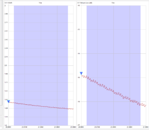
With the antenna back in the air, I went inside to check its performance. The results on 40, 20, and 10 meters were exactly as expected. Unfortunately, I had created an entirely new problem on 15 meters!
I had solved one issue, only to create another. Fortunately, I have almost solved this new problem. In my next post, I'll explain what happened and how I fixed it.
RFI is either giving or receiving.
 |
| Without any RFI issue. |
In my last post, I was on the receiving end of RFI—you can read about that HERE. This post is about being on the other side of the equation: being the source of the RFI.
I have a Raspberry Pi 4B running Open HamClock Backend. It's a very handy program that provides a wealth of useful operating information. During the Canada Day Contest last week, I noticed that whenever I transmitted on 15m at 100 watts CW, the monitor connected to the Pi 4B would go completely blank. As soon as I stopped transmitting, the display would immediately return.
Blank monitor screen.
This time, instead of being the victim of RFI from a noisy wall wart, my own RF signal was causing the problem. You could say I had become the RFI source.
It was time to investigate. My first suspicion turned out to be correct—the HDMI cable running from the Pi 4B to the monitor. I had a spare Mix 31 ferrite toroid, so I wound a few turns of the HDMI cable through it. The problem disappeared immediately. That quick fix allowed me to get back to contesting, knowing I could look into the issue more thoroughly later.
The Raspberry Pi 4B came with an HDMI cable, but I assumed it probably wasn't the highest-quality cable available. I examined it closely but couldn't find a manufacturer, model number, or even a country of origin.

Old HDMI cable
All of the USB cables in my station are made by Tripp Lite. In total, I now have seven Tripp Lite cables in service performing various tasks. I've never had an issue with any of them, and they have consistently earned an excellent reputation for quality. Based on that experience, I ordered a Tripp Lite HDMI-to-Micro-HDMI cable for the Pi 4B. Yes, I could have simply left the ferrite toroid on the original cable, but I prefer to solve a problem at its source whenever possible.
So, what makes the Tripp Lite cable better? It features excellent shielding, heavier-gauge conductors, superior overall construction, and is backed by a lifetime warranty.

New Tripp-Lite cable
When the new cable arrived, I removed the ferrite toroid from the original cable and repeated the test. As expected, transmitting on 15m caused the monitor to go blank once again. I then replaced the original cable with the new Tripp Lite cable—without using the ferrite toroid—and transmitted under the same conditions. This time, the monitor remained stable with no blanking whatsoever.
Another RFI adventure solved through a little troubleshooting and some simple testing. Sometimes the simplest solution really is the right one.
RFI found and removed
 |
| LED RFI |
Where we live, I have a very quiet noise floor and have enjoyed it for years. Recently, however, while operating on 40 meters, I noticed an offending signal on the Icom IC-7610 waterfall display. The noise repeated approximately every 15 kHz. If a CW signal happened to fall within the hash, I was unable to hear it.
I tried using the radio's noise reduction feature, which reduced the interference somewhat. However, increasing the noise reduction too much tends to distort CW signals, so that was not a satisfactory solution. I also tried the noise blanker, but it had no effect on the noise.
I began to think about what had recently changed in our home. Sure enough, my wife had recently purchased an LED light for her sewing table. As a quick test, I turned off and unplugged the new light. Immediately, 40 meters returned to its normally quiet state. When I plugged the light back in and turned it on, the offending signal returned.
 |
| The new problem. |
I had several Fair-Rite Mix 31 snap-on ferrites, so I installed them on the power cord near the wall wart and where the cord connected to the light. This made only a very small difference. The LED light's wall wart was plugged into a power bar, so I also added ferrites to the power bar's 120-volt power cord. Again, there was little improvement.
Next, I dug out my trusty battery-powered Eton radio and tuned it to a quiet spot on the AM broadcast band. Extending the antenna, I began hunting for the source of the RFI. When I moved the antenna close to the LED light's wall wart, the radio burst into noise.

I considered trying a different power supply, but the LED light required 24 volts DC and all the spare adapters I had were 12 volts. After doing some online research, I came across a Mean Well power supply that appeared to have excellent filtering specifications. I ordered the correct model from Mouser Canada and hoped it would solve the problem.
 |
| Offending wall wart. |
A few days later, it arrived. I plugged it in and—wow—the offending noise was completely gone. I placed the AM radio right beside the new Mean Well adapter and found it to be very quiet. It was satisfying to track down the source of the interference and solve the problem.
The lesson learned was simple: not all power supplies are created equal. In this case, the inexpensive wall wart supplied with the LED light was generating significant RF noise, while the replacement Mean Well supply was virtually silent on the air.
 |
| 40m back to normal |
 |
The new Mean Well
|