 |
 Ham College 142
Ham College episode 142 is now available for download.
General Exam Questions Part 3.
G1C – Transmitter power regulations; data emission standards; 60-meter operation requirements.
Demonstration of PEP vs Average Power. Effective Radiated Power.
https://hamcollege.tv
Download
YouTube
Key Topics Covered:
PEP vs. Average Power: The hosts provide a practical demonstration using a transceiver and a True Peak Reading wattmeter to explain the differences between Peak Envelope Power (PEP) and average power across various modes like Single Sideband (SSB), AM, and FM (3:25 – 18:28).
Exam Preparation: The hosts review specific exam questions related to:
Power Limits: Maximum transmitter power for different bands, such as the 30-meter (10.140 MHz) band (19:05 – 21:53) and the 12-meter band (21:56 – 23:07).
60-Meter Band Rules: Specific operational requirements including bandwidth limits (23:08 – 25:06) and necessary log-keeping protocols (25:07 – 27:26).
General Power Limits: Discussing the 1,500-watt PEP limit for most HF bands (27:27 – 31:58).
Digital Protocols: The requirement to publicly document technical characteristics before using a new digital protocol on the air (32:08 – 35:36).
Effective Radiated Power (ERP): A discussion on calculating ERP, accounting for transmission line losses and connector signal attenuation. (38:03 – 44:44).
Community Updates: The hosts share upcoming plans for the Huntsville Hamfest (45:56 – 48:47) and mention the launch of a new dedicated Ham College YouTube channel.
George Thomas, W5JDX, is co-host of AmateurLogic.TV, an original amateur radio video program hosted by George Thomas (W5JDX), Tommy Martin (N5ZNO), Peter Berrett (VK3PB), and Emile Diodene (KE5QKR). Contact him at [email protected].
Amateur Radio Weekly – Issue 432

Family of KY student says deputy seized child’s radios without warrant. They’re suing
A Somerset family has filed a lawsuit against the county’s school board and local law enforcement, alleging a deputy wrongly seized two-way radios from a student without a warrant.
Lexington Herald Leader
The integrity question: Inside the WRTC 2026 Multiplier Investigation
Public log analysis has raised serious questions about suspected pirate callsigns, disputed multipliers, and how the world’s premier radiosport competition should respond.
Q5 Magazine
MODEM73
An open source software modem that works with any HF, VHF, or UHF radio capable of 2400 Hz of bandwidth.
MODEM73
Expanding Technician privileges: The fix needs a push
There’s a real, already-written fix for one of Technician licensees’ most common complaints — and it’s been sitting in an FCC docket since 2018.
EtherHam
What’s new at Digital Library of Amateur Radio & Communications — July 2026
DLARC has significantly expanded the AMSAT Symposium archive, adding about 250 new items from AMSAT Space Symposium events. Newly archived material includes audio recordings of the 2007-2008 presentations.
Zero Retries
SDRoxide: Software-defined transceiver
A powerful SDR transceiver client with a GPU panadapter, dual VFOs, neural noise reduction, built-in skimmers, a full stack of digital modes and a live 3D space-weather globe — wrapped in a cyberpunk interface and running native on Linux, macOS & Windows, or streamed to any browser.
SDRoxide
Reticulum
The appeal of reticulum is that it seems to extend the LoRa thing to include mini web pages and a different way of interacting. A cross between packet, the general internet, and normal messaging.
G7KSE
Zero Retries Digital Conference 2026 call for papers
A typical technical paper for ZRDC is a short (typically 5-10 pages) but in-depth explanation of a project, experiment, or new technique.
Zero Retries
I made an AFSK RTTY encoder for the Sony PSP
The PSP is acting purely as an encoder, generating the RTTY audio tones which are then received and decoded externally.
Reddit
TunerScope: A browser app to help optimize HDTV antenna positioning with an RTL-SDR
TunerScope has a few interesting features, including the use of spectrum stitching to visualize the full 6 MHz + wide ATSC signals as the RTL-SDR only provides 2.56 MSPS max.
RTL-SDR
Olivia spotting
View live on-air station spots, filter by mode/band, and spot station activity in real-time.
OliviaDigitalMode.org
Feds hunting for German spy found a 12-year-old radio genius instead
Francis “Frank” Ryder, whose remarkable talent for radio led federal agents to his Brooklyn home during World War I before he went on to found the Suffolk County Radio Club.
South Shore Press
A visit to Nashville’s WSM AM
Photos from the transmitter site of the station that birthed the Grand Ole Opry.
RadioWorld
Video
This 3D printed trailer hitch antenna mast mount is awesome
Printed on Bambu P1S with Bambu PETG, 10 walls, 40% infill.
Ham Radio Tube
40M V Dipole vs 130′ EFHW
The results are not what you expect.
Hounds and ham
Get Amateur Radio Weekly in your inbox.
Sign-up here
Amateur Radio Weekly is curated by Cale Mooth K4HCK. Sign up free to receive ham radio's most relevant news, projects, technology and events by e-mail each week at http://www.hamweekly.com.
ICQPodcast Episode 489 – STEM and Radio for a Brighter Future
In this episode, we join Martin Butler M1MRB, Chris Howard (M0TCH), Martin Rothwell (M0SGL), Frank Howell (K4FMH), Bill Barnes (WC3B) and Leslie Butterfields (G0CIB) to discuss the latest Amateur / Ham Radio news. Colin Butler (M6BOY) rounds up the news in brief, and the episode's feature is STEM and Ham Radio Works.
We would like to thank our Chris Carini, (GW4RER), Walter Washburn, (KT0D), Constantine Papas (KL0S) and monthly and annual subscription donors for keeping the podcast advert free. To donate, please visit - http://www.icqpodcast.com/donate
- HAMgpt Launches as an AI Assistant Built Around Your Station
- Keeping Teams Connected Where the Network Isn't
- Scientists Building Massive Deep Synoptic Array in Nevada Desert
- FCC Clears Orbital Mirror Satellite Despite Widespread Objections
- aprs.world — A Free, Modern Live APRS Map in 11 Languages
- RSGB Club Finder Back Online After Redevelopment
- Peter the First Island DXpedition Seeks Operators
- Icom RS-BA1 Version 2 (Version 2.81) & RS-R8600 (Version 1.02) Software Updates
Colin Butler, M6BOY, is the host of the ICQ Podcast, a weekly radio show about Amateur Radio. Contact him at [email protected].
Amateur Radio Weekly – Issue 431
APRS On the Air
Let’s create a new Amateur Radio activity and supporting software that brings the activator-and-chaser game of Parks on the Air and Summits on the Air to APRS.
K0TFU
China is using Ham Radio in its territorial claim over the South China Sea
An article goes into great depths to use decisions by the ARRL in the 1990’s and a multi-national DX-petitions to give legitimacy to its claim.
Andrew Woodward
FT8 on CB Channel 26
FT8 has taken over Channel 26 USB (27.265 MHz) as an incredibly efficient way to rack up 11-metre DX contacts on the CB band.
EA5IYL
FT8 Is a fad, and other heresies
People are growing weary of too much tech. Digital detox is trending in the non-radio world.
KE9V
Contact the ISS
Some ISS crew members make random, unscheduled, Amateur Radio voice contacts with earth-bound Radio Amateurs.
ARISS
VHF for Parks On The Air?
Don’t overlook the VHF bands, especially 2m FM.
K0NR
School students successfully launch high-altitude balloon into the atmosphere
The Hutt Valley Amateur Radio Club helped with the transmitters inside the payload.
RNZ
Move Meshtastic up on your list
The worst kept secret in communications.
Off Grid Ham
A look at DXpedition funding
Let’s go over these different funding sources, why each is important, and how they come together to make a DXpedition go.
OnAllBands
ARRL June 2025 VHF Contest replay
Video map version.
K5ND
How Amateur Radio built the Indonesian Internet
PaguyubanNet, packet radio and the pioneers of 1986-1994.
HamRaio.my
Video
SOTA by bicycle in Puerto Rico
Elecraft KX2 + AX1.
WP4TZ
RV Ham Shack
My complete RV Ham Radio setup explained.
KM4ACK
Get Amateur Radio Weekly in your inbox.
Sign-up here
Amateur Radio Weekly is curated by Cale Mooth K4HCK. Sign up free to receive ham radio's most relevant news, projects, technology and events by e-mail each week at http://www.hamweekly.com.
News: Olivia Digital Modes on HF
Greetings Olivia and digital mode operators,
GREAT NEWS! WEBSITE UPDATE!
Here are the big three new features:

Live spotting is now available!
- Live Olivia spotting. Just like on POTA and other sites, this is a live show and tell of your activity either by self spotting, or spotting stations you copy. Dedicated live spot page, you can view even on a cell phone.
We are excited to announce a major new feature now live on OliviaDigitalMode.org: an interactive Live Station Spotting tool designed specifically for our digital HF community. Inspired by popular spotting platforms like DXWatch and POTA.app, this system makes it easier than ever to see who is active on the bands, find open Olivia QSOs, and share your own station reports in real time.
Come Join the Live Spotting of Olivia Digital Mode
Whether you are hunting for a contact or tracking band openings across different bandwidths and tone counts, the new spotting tool brings several powerful capabilities straight to your browser:
- Real-Time Live Feed: The spotting page automatically refreshes every 15 seconds, ensuring you always see the latest on-air activity without needing to manually refresh the page.
- Smart Spot Grouping: When multiple operators spot the same station, the system automatically groups those reports together into a single clean line. Instead of duplicate entries cluttering your view, you will see the station, frequency, mode, and a list of all operators who spotted them.
- Timeframe Visual Highlighting: You can easily filter for fresh activity. By selecting a window of 5 minutes, 15 minutes, 30 minutes, or 1 hour, brand-new spots are visually highlighted so you can jump on active signals immediately.
- Flexible Display Options: On the dedicated spotting page, you can choose how many spots to display at once (from 10 up to 250 rows) and toggle between a grouped callsign layout or a detailed chronological log.
- At-a-Glance Homepage Widget: A lightweight summary widget on the main homepage shows the top 5 to 10 most recent spots the moment you arrive on the site.
- Fast Performance and Historical Archives: Active spots stay on the main board for 12 hours to keep queries ultra-fast. After 12 hours, spots automatically move to a historical archive where they remain available for band activity research and propagation analysis.
To keep the spotting board reliable and free of spam, posting new spots will require a simple, free operator account. When you register, you will just need to include a short note for the site administrators to verify your callsign and approve your posting access. Once approved, you can log in anytime and share spots whenever you are on the air.
- Live Calendar of Olivia Events. I have now put live the active calendar functionality on the site, and seeded it with possible calendar events. I will start planning our upcoming events – which require YOUR input on such things as, monthly sprints, special events that you want to do, and, our quarterly QSO parties.
- Feedback form. This is a community website. Now, you can leave feedback; what would you like on the website. What should be different? What is not working? What is working? Please leave us feedback.
Come be a part of this conversational digital mode!
Visit, subscribe: NW7US Radio Communications and Propagation YouTube Channel
Part 2 of….. Antenna solve one problem to only create another.
 |
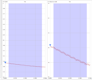
| My new SWR on 15M |

 |
| Issue found. |
Mike Weir, VE9KK, is a regular contributor to AmateurRadio.com and writes from New Brunswick, Canada. Contact him at [email protected].
VHF for Parks On The Air?
Parks On The Air (POTA) has exploded in popularity, with most of the activity on the HF bands. That makes sense — HF gives you the long-distance contacts and the big pileups. But don’t overlook the VHF bands, especially 2m FM. Two meter FM is simple, highly portable, and often an easy way to knock ... Read more
The post VHF for Parks On The Air? appeared first on Above Average Terrain.
Bob Witte, KØNR, is a regular contributor to AmateurRadio.com and writes from Colorado, USA. Contact him at [email protected].
 Ham Radio Deluxe |
 W5SWL Electronics |
 Ham Radio Prep |
 KB3IFH QSL Cards  Hip Ham Shirts  HamRadioAuctions HamRadioAuctions Reliance Antennas Reliance Antennas Enigma Shop Enigma Shop |  morseDX  Ni4L Antennas  R&L Electronics R&L Electronics antennas.us antennas.us QRV QRV |
- Matt W1MST, Managing Editor
