Posts Tagged ‘repair’
 In The Loop! – Repairing a MFJ-1788
Over the last few years I've seen various musings about magnetic loop antennas and their supposed efficiency and performance. I had even toyed with the idea of building one considering the eye-watering prices commercial ones are sold for! Sadly that idea had been added to the big pile of 'to-do' projects.
Earlier this year I spotted a posting on social media by a member of my club who had brought a MFJ-1788 second hand who was having issues with it not working. I had offered some advice on its repair and glibly offered to take it off his hands should he want to dispose of it. A few months later I got a message asking if I was still interested? I certainly was at the price he wanted.
I collect it at the club meeting a fortnight ago still with a 5ft pole still attached as a bonus! Thankfully it fitted in the car (just).
I downloaded the manual and schematic from the MFJ website and I saw there were conspicuous warnings about using an 'isolated' power supply both in the manual and on the back of the controller, with ominous warnings of damage if you didn't. Most shack supplies have the negative/black pin connected to the chassis/ground.
The controller had come to me supplied with a standard fused lead, you know the ones that come to connect your ATU/SWR meter lamp to the shack supply? Mmmm.. my spider sense was tingling!
I pulled out a small double-insulated 12V plug-in supply from my collection (you can spot them as they often have a plastic earth pin) and with nothing else connected powered up the controller. The meter lamp came on and some of the LEDS briefly flickered and heard a few clicks from the internal buzzer then nothing. Pressing buttons did nothing and then I caught the unmistakable scent of burning electronics!
Opening the box up on the bench quickly spotted the source, the regular had well and truly smoked, but since nothing had been connected the short must have been in the controller itself (and it was not the dodgy wires that look like they had been victims to a wayward soldering iron)

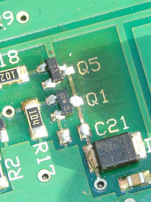
Inspecting the rest of the board it was clear that it had been repaired (badly) once before, the two main transistors/FETs (Q1/Q5) used to control the motor clearly showed signs of being replaced (misaligned and with tell-tale scorching from an hot air gun)
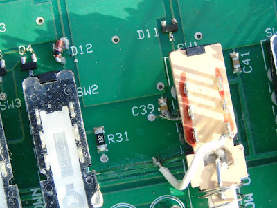
a SMD diode had been swapped and one of the 'fine tune' switches had been replaced, its removal had obviously been problematic taking with it some of the through hole copper and adjacent tracks which had been lifted/damaged.
Before opening up the box I had expected to see 'through hole' components and DIL logic ICs not for it to be all surface mounted. Undaunted I went through the parts list and decided to get replacements for all the semiconductor parts not knowing at this stage what I would have to replace. Getting two of each device in some cases five or ten of each due to minimum order quantity, the staggering cost was £8 ($11) including postage!
While waiting for the parts to arrive I decided to check out the actual antenna head. I removed the plastic covering and attempted to extract it from the pole..
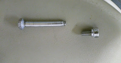
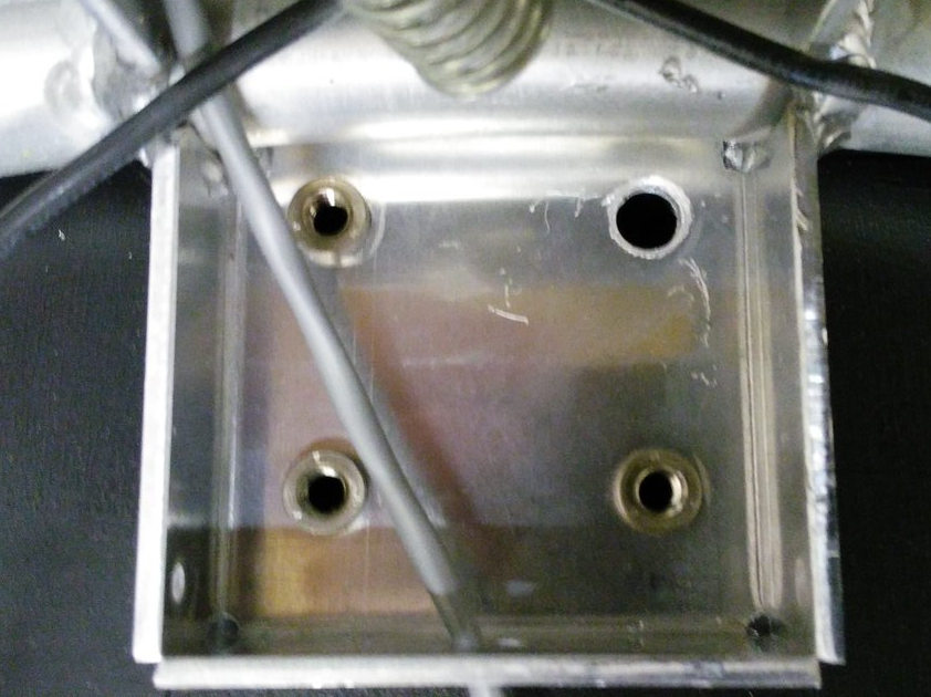
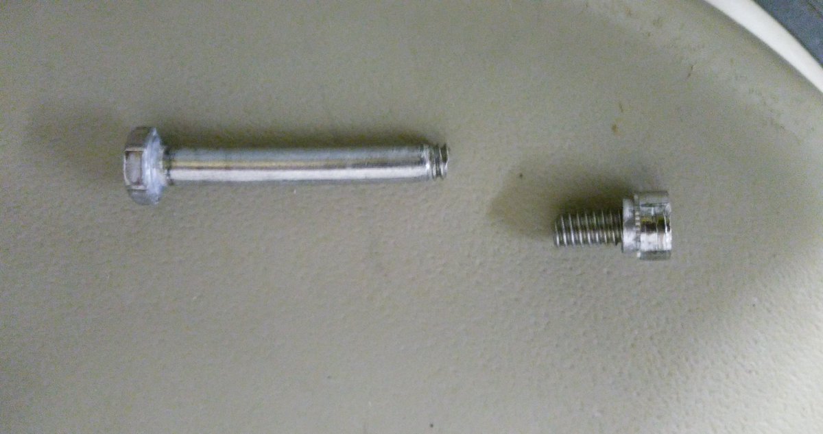
First issue I had was the mounting. One bolt had seized, the nut inserts are held in quite soft aluminium so not surprisingly the insert came out out the mounting when trying to remove it. Using grips to hold the insert the bolt still refused to turn and in the end it sheared off with very little force! Obviously quality fittings these!

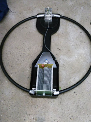
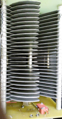
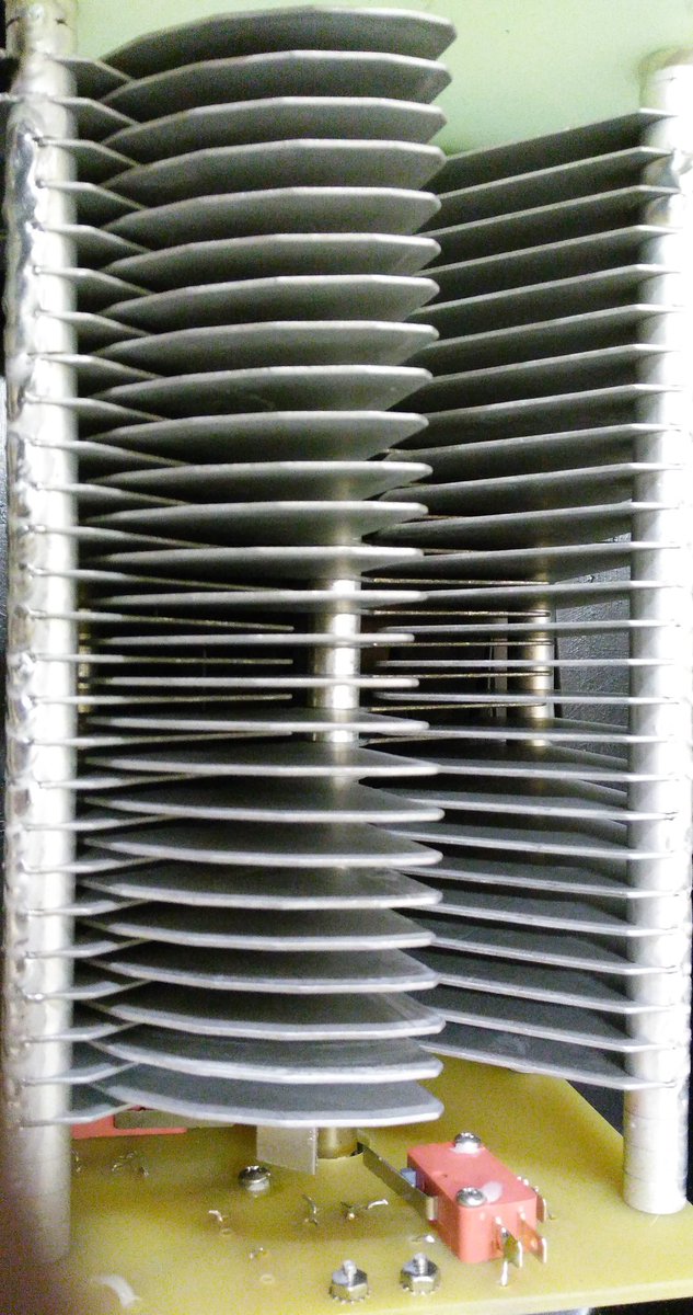
The variable capacitor was suffering a common problem due to poor quality control, the fins had gone out of alignment. Each fin is a separate assembly held on a shaft with a nut to compress them together. It is a simple fix, just realigned and tightened the bolt. The limit switches and motor connection were okay (another common problem) Applying a voltage to the coax connector the motor turned fine, reversing the voltage reversed the direction of turn, the vanes going fully in and fully out before the limit switches activated.
The components arrived prompty and so I got the hot air gun out and set about repairing the board.

I started off replacing the regulator (and the damaged power track) and Q1/Q5 and we had the flickering of life. Pressing the AUTO TUNE button the LED lit and there was 9V across the antenna connector, pressing the other AUTO TUNE button had -9V across. This is why you need an isolated power supply since it reverses the voltage to control direction. The radio doesn't see any of this voltage due to the bias-t arrangement. However if the supply shared the shack ground you would short out the supply, but the current would go via all those delicate electronics! Which is what I think had happened.
It soon became clear that most devices had suffered damage and so I ended up replacing the regulator 78L12, Q1 (SN7002 FET), Q2 (MMBT3906), Q5 (MMBT3906) all the logic ICs CMOS 4001, 4011 and 4066 and the LM324 Quad op-amp chip. I also gave the board a good clean since was covered in grime and flux residue.
Once I was happy the controller was reassembled and connected to my FT-857D on minimum power and the loop antenna propped up against the side of the shack. Success! I was able to successful tune it as per the instructions on 40m and 10m, the two extremes of operation and could here the telltale rise in receive noise as it became resonant.
I have yet to put the loop up in situ for a proper evaluation but have refurbished an old TV rotator to mount it on. I have fitted some nice new quality bolts. The black insulating tape round the loop has been removed, preferring the silver look myself.
Assuming it does performs and will find out this weekend, I have paid a total of £65 ($90) (£50 for the initial purchase the rest for replacement parts) which is an absolute bargain as to buy new it is expensive.. very expensive!
One of the main supplier in the UK, have it on sale for £699 ($940) but this includes their engineers inspecting and rebuilding each one before shipping! (Can only be due to poor build quality control and warranty claims) the RRP seems to be around £570 ($770)
It does amaze me how much this units costs new. While the loop construction is generally good, the mounting fittings appear to be poor and the issues with the capacitor and quality control are widely reported.
The components in the controller are not expensive, the switches, meter, box are the usual MFJ fare and the design is quite old (the PCB has copyright 1998 on the silk screen) the auto-tune process requires the radio to be putting RF into a mismatched load for up to a minute and even with low power and SWR protection this isn't good for the radio PA.
Perhaps most surprising is given the risk of damage due to incorrect use is why firstly the loop isn't supplied with a power supply anyway as they only cost a pittance and secondary why their isn't any protection built in? I intend fitting a simple 100mA fuse to offer some protection should a problem occurs.
If the loop performs it may be another project to build a better controller, there are a few designs out there on the internet using Arduino and DDS devices to create auto-tuners. Has that pile of potential projects just grows taller?
73 for now.. and promise to post a bit more regularly
Earlier this year I spotted a posting on social media by a member of my club who had brought a MFJ-1788 second hand who was having issues with it not working. I had offered some advice on its repair and glibly offered to take it off his hands should he want to dispose of it. A few months later I got a message asking if I was still interested? I certainly was at the price he wanted.
I collect it at the club meeting a fortnight ago still with a 5ft pole still attached as a bonus! Thankfully it fitted in the car (just).
 |
| Loop as purchased, with pvc tape covering loop |
 | |
| Control Box |
I downloaded the manual and schematic from the MFJ website and I saw there were conspicuous warnings about using an 'isolated' power supply both in the manual and on the back of the controller, with ominous warnings of damage if you didn't. Most shack supplies have the negative/black pin connected to the chassis/ground.
The controller had come to me supplied with a standard fused lead, you know the ones that come to connect your ATU/SWR meter lamp to the shack supply? Mmmm.. my spider sense was tingling!
I pulled out a small double-insulated 12V plug-in supply from my collection (you can spot them as they often have a plastic earth pin) and with nothing else connected powered up the controller. The meter lamp came on and some of the LEDS briefly flickered and heard a few clicks from the internal buzzer then nothing. Pressing buttons did nothing and then I caught the unmistakable scent of burning electronics!
Opening the box up on the bench quickly spotted the source, the regular had well and truly smoked, but since nothing had been connected the short must have been in the controller itself (and it was not the dodgy wires that look like they had been victims to a wayward soldering iron)

Inspecting the rest of the board it was clear that it had been repaired (badly) once before, the two main transistors/FETs (Q1/Q5) used to control the motor clearly showed signs of being replaced (misaligned and with tell-tale scorching from an hot air gun)
a SMD diode had been swapped and one of the 'fine tune' switches had been replaced, its removal had obviously been problematic taking with it some of the through hole copper and adjacent tracks which had been lifted/damaged.


Before opening up the box I had expected to see 'through hole' components and DIL logic ICs not for it to be all surface mounted. Undaunted I went through the parts list and decided to get replacements for all the semiconductor parts not knowing at this stage what I would have to replace. Getting two of each device in some cases five or ten of each due to minimum order quantity, the staggering cost was £8 ($11) including postage!
While waiting for the parts to arrive I decided to check out the actual antenna head. I removed the plastic covering and attempted to extract it from the pole..

First issue I had was the mounting. One bolt had seized, the nut inserts are held in quite soft aluminium so not surprisingly the insert came out out the mounting when trying to remove it. Using grips to hold the insert the bolt still refused to turn and in the end it sheared off with very little force! Obviously quality fittings these!
The variable capacitor was suffering a common problem due to poor quality control, the fins had gone out of alignment. Each fin is a separate assembly held on a shaft with a nut to compress them together. It is a simple fix, just realigned and tightened the bolt. The limit switches and motor connection were okay (another common problem) Applying a voltage to the coax connector the motor turned fine, reversing the voltage reversed the direction of turn, the vanes going fully in and fully out before the limit switches activated.
The components arrived prompty and so I got the hot air gun out and set about repairing the board.

I started off replacing the regulator (and the damaged power track) and Q1/Q5 and we had the flickering of life. Pressing the AUTO TUNE button the LED lit and there was 9V across the antenna connector, pressing the other AUTO TUNE button had -9V across. This is why you need an isolated power supply since it reverses the voltage to control direction. The radio doesn't see any of this voltage due to the bias-t arrangement. However if the supply shared the shack ground you would short out the supply, but the current would go via all those delicate electronics! Which is what I think had happened.
It soon became clear that most devices had suffered damage and so I ended up replacing the regulator 78L12, Q1 (SN7002 FET), Q2 (MMBT3906), Q5 (MMBT3906) all the logic ICs CMOS 4001, 4011 and 4066 and the LM324 Quad op-amp chip. I also gave the board a good clean since was covered in grime and flux residue.
Once I was happy the controller was reassembled and connected to my FT-857D on minimum power and the loop antenna propped up against the side of the shack. Success! I was able to successful tune it as per the instructions on 40m and 10m, the two extremes of operation and could here the telltale rise in receive noise as it became resonant.
I have yet to put the loop up in situ for a proper evaluation but have refurbished an old TV rotator to mount it on. I have fitted some nice new quality bolts. The black insulating tape round the loop has been removed, preferring the silver look myself.
 |
| Waiting to be put on the pole |
 |
| Shiny once again |
Assuming it does performs and will find out this weekend, I have paid a total of £65 ($90) (£50 for the initial purchase the rest for replacement parts) which is an absolute bargain as to buy new it is expensive.. very expensive!
One of the main supplier in the UK, have it on sale for £699 ($940) but this includes their engineers inspecting and rebuilding each one before shipping! (Can only be due to poor build quality control and warranty claims) the RRP seems to be around £570 ($770)
It does amaze me how much this units costs new. While the loop construction is generally good, the mounting fittings appear to be poor and the issues with the capacitor and quality control are widely reported.
The components in the controller are not expensive, the switches, meter, box are the usual MFJ fare and the design is quite old (the PCB has copyright 1998 on the silk screen) the auto-tune process requires the radio to be putting RF into a mismatched load for up to a minute and even with low power and SWR protection this isn't good for the radio PA.
Perhaps most surprising is given the risk of damage due to incorrect use is why firstly the loop isn't supplied with a power supply anyway as they only cost a pittance and secondary why their isn't any protection built in? I intend fitting a simple 100mA fuse to offer some protection should a problem occurs.
If the loop performs it may be another project to build a better controller, there are a few designs out there on the internet using Arduino and DDS devices to create auto-tuners. Has that pile of potential projects just grows taller?
73 for now.. and promise to post a bit more regularly
Repaired my ATU
Merry Christmas!
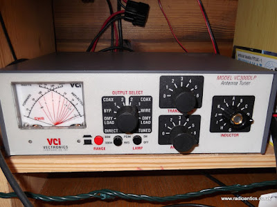
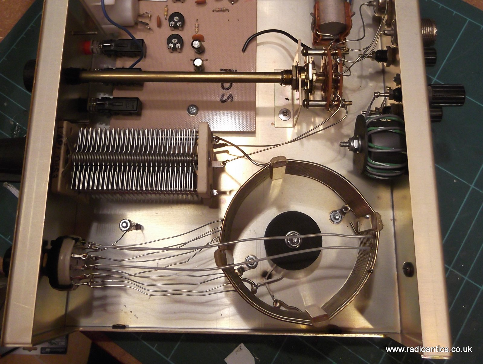
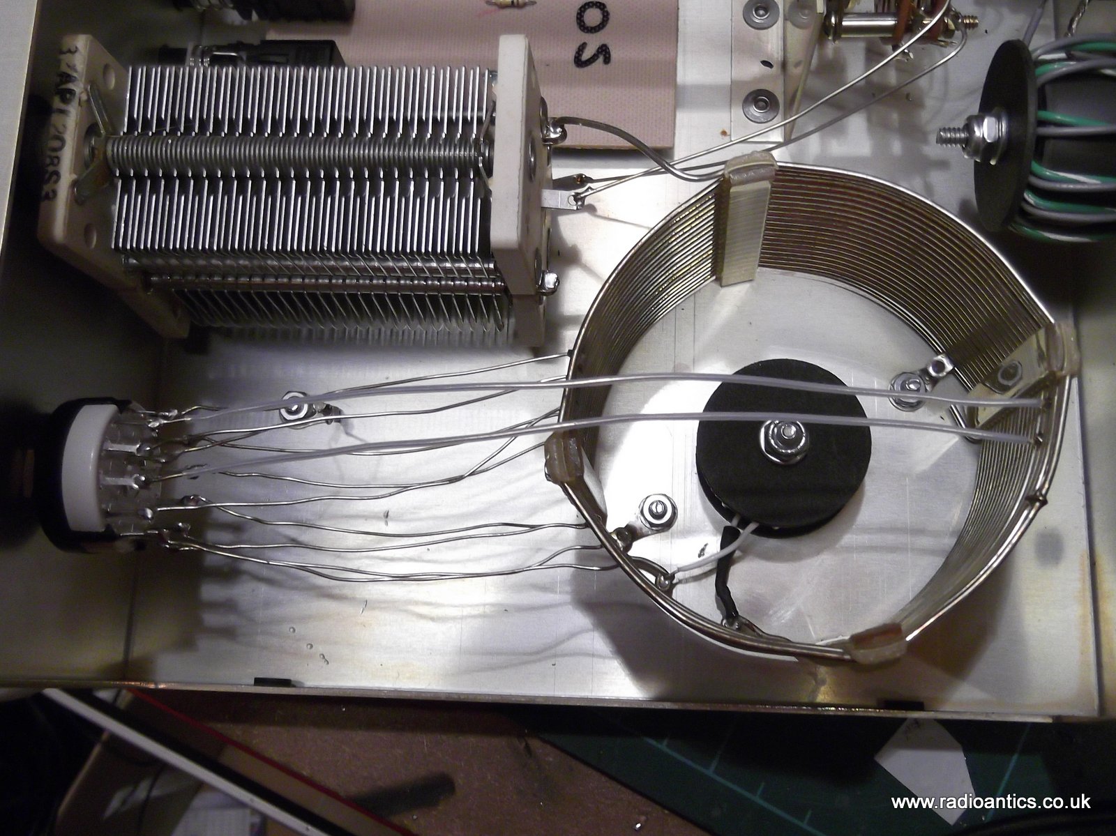
Not wishing to contend with an evening of dire XYL style Christmas TV (Strictly Come Dancing, Call the Midwife and Downton Abbey) I escaped into the shack and decided to repair my Vectronics VC300DLP Antenna Tuner. I got this ATU second hand last year and while it has been serviceable it had become temperamental of late. The units rotary inductor switch had become stiff and suddenly I was unable to match the OCFD on some bands so it had clearly broken.
I had a 12-position switch (rated at 5A) and knob, originally sourced for an abandoned project and hoped it would be suitable. The existing switch knob on the ATU wasn't an original, I'd assumed it had replaced one lost or broken. When I removed the cover it was clear that the whole switch had already been changed at sometime.
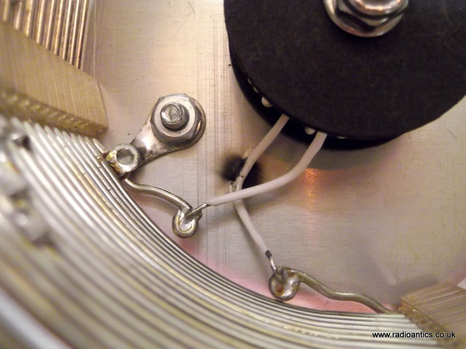
I also noticed a prominent burn mark inside the inductor coil, caused by a clear break in the insulation of the wire which was resting on the grounded bottom plate.

I know the previous owner of the ATU has a 300W RM BLA-350 linear amplifier, whereas I only normally operate around 30W maximum at my QTH, so not sure how much of this arcing I had caused but it needed sorting! A little over half an hour with the soldering iron and I had replaced the switch and slipped some heat shrink over the broken insulation and re-soldered the wire, lifting it off the ground plate.
The ATU seems to work well, now fitted with a new knob (just missing a cap at the moment) the switch turns nicely. I also cleaned up the SO-239 connectors on the back as they were tarnished and oxidised. I used a small bit of contact cleaner on some cotton buds to clean up the threads and the centre pins, removing a surprising amount of crud. The patch and antenna leads now screws on much better.
With the Mother--in-law staying with us over the festive period I suspect I may be in the shack quite a bit, I have plenty of jobs and half finished projects to keep me busy!

Not wishing to contend with an evening of dire XYL style Christmas TV (Strictly Come Dancing, Call the Midwife and Downton Abbey) I escaped into the shack and decided to repair my Vectronics VC300DLP Antenna Tuner. I got this ATU second hand last year and while it has been serviceable it had become temperamental of late. The units rotary inductor switch had become stiff and suddenly I was unable to match the OCFD on some bands so it had clearly broken.
I had a 12-position switch (rated at 5A) and knob, originally sourced for an abandoned project and hoped it would be suitable. The existing switch knob on the ATU wasn't an original, I'd assumed it had replaced one lost or broken. When I removed the cover it was clear that the whole switch had already been changed at sometime.
I also noticed a prominent burn mark inside the inductor coil, caused by a clear break in the insulation of the wire which was resting on the grounded bottom plate.
I know the previous owner of the ATU has a 300W RM BLA-350 linear amplifier, whereas I only normally operate around 30W maximum at my QTH, so not sure how much of this arcing I had caused but it needed sorting! A little over half an hour with the soldering iron and I had replaced the switch and slipped some heat shrink over the broken insulation and re-soldered the wire, lifting it off the ground plate.
The ATU seems to work well, now fitted with a new knob (just missing a cap at the moment) the switch turns nicely. I also cleaned up the SO-239 connectors on the back as they were tarnished and oxidised. I used a small bit of contact cleaner on some cotton buds to clean up the threads and the centre pins, removing a surprising amount of crud. The patch and antenna leads now screws on much better.

With the Mother--in-law staying with us over the festive period I suspect I may be in the shack quite a bit, I have plenty of jobs and half finished projects to keep me busy!
Repaired my ATU
Merry Christmas!
Not wishing to contend with an evening of dire XYL style Christmas TV (Strictly Come Dancing, Call the Midwife and Downton Abbey) I escaped into the shack and decided to repair my Vectronics VC300DLP Antenna Tuner. I got this ATU second hand last year and while it has been serviceable it had become temperamental of late. The units rotary inductor switch had become stiff and suddenly I was unable to match the OCFD on some bands so it had clearly broken.
I had a 12-position switch (rated at 5A) and knob, originally sourced for an abandoned project and hoped it would be suitable. The existing switch knob on the ATU wasn't an original, I'd assumed it had replaced one lost or broken. When I removed the cover it was clear that the whole switch had already been changed at sometime.
I also noticed a prominent burn mark inside the inductor coil, caused by a clear break in the insulation of the wire which was resting on the grounded bottom plate.
I know the previous owner of the ATU has a 300W RM BLA-350 linear amplifier, whereas I only normally operate around 30W maximum at my QTH, so not sure how much of this arcing I had caused but it needed sorting! A little over half an hour with the soldering iron and I had replaced the switch and slipped some heat shrink over the broken insulation and re-soldered the wire, lifting it off the ground plate.
The ATU seems to work well, now fitted with a new knob (just missing a cap at the moment) the switch turns nicely. I also cleaned up the SO-239 connectors on the back as they were tarnished and oxidised. I used a small bit of contact cleaner on some cotton buds to clean up the threads and the centre pins, removing a surprising amount of crud. The patch and antenna leads now screws on much better.
With the Mother--in-law staying with us over the festive period I suspect I may be in the shack quite a bit, I have plenty of jobs and half finished projects to keep me busy!
Repairing a Kenwood TR9500, Part4
The troublesome TR9500 has developed another fault, well it has likely had this fault since I've owned it but I have only just spotted it.
After making repairs to the microphone amplifier and the receiver pre-amplifier the rig seemed to be working fine, I'd even used it several times during the UKAC contests with some success.
The 70cm band is under used locally and activity seems largely restricted to repeaters. Due to it's vintage the TR9500 doesn't have CTCSS tones and so cannot be used to access repeaters without some modification and I've been looking at adding a CTCSS board.
In the meantime I really wanted to use the TR9500 a bit more and was hoping to make it part of a satellite station, the TR9500 acting as the UHF uplink transmitter (LSB) and the VHF 2m TR9000 as the downlink receiver (USB) for the AO73 (FUNCube-1) and other satellites.
The satellite portion of the band plan is at 435-438MHz and it was when setting this up I discovered the TR9500 neither received or transmitted in the upper part of the 70cm band (435-440MHz) below this everything was hunky-dory.
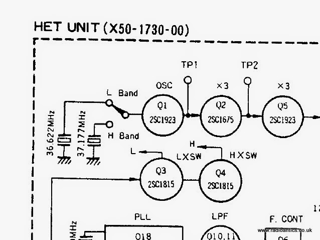
It hasn't taken long to locate the issue, the HET unit employs two crystals L33 (36.6222MHz), L34 (37.1777MHz) which are switched in to the oscillator Q1 depending on the selected frequency. L33 being referred to as low band, L34 as high band the switching occurring around 435MHz.
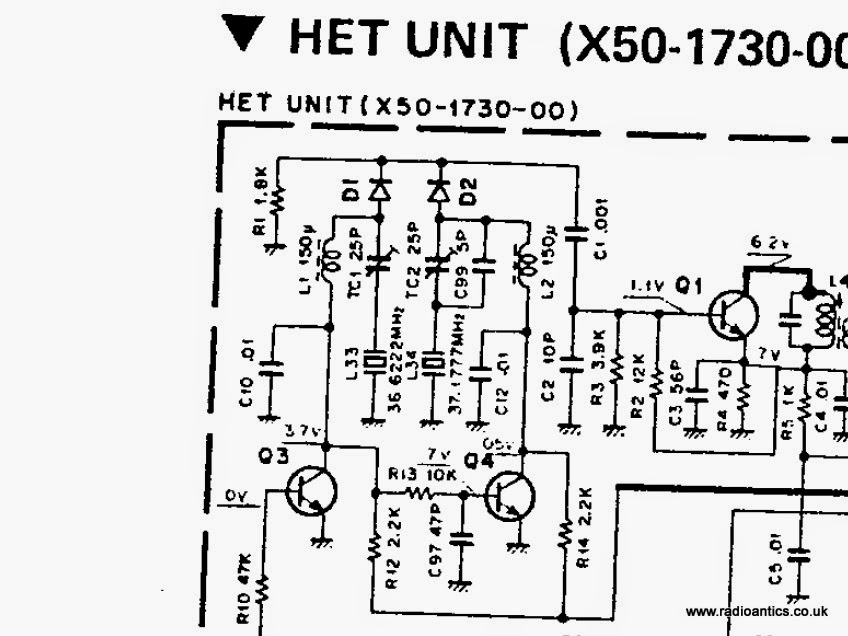
The switching HL signal (via R10) and transistors Q3/Q4 are working correctly it is just crystal L34 is not resonating. The surrounding diodes, capacitors, inductors and resistors all look fine, no obvious shorts or broken joints.
I have to do some more diagnostics to rule out any of the passive components but if it is the case that the crystal has failed then it may prove difficult to source an economical replacement.
After making repairs to the microphone amplifier and the receiver pre-amplifier the rig seemed to be working fine, I'd even used it several times during the UKAC contests with some success.
The 70cm band is under used locally and activity seems largely restricted to repeaters. Due to it's vintage the TR9500 doesn't have CTCSS tones and so cannot be used to access repeaters without some modification and I've been looking at adding a CTCSS board.
In the meantime I really wanted to use the TR9500 a bit more and was hoping to make it part of a satellite station, the TR9500 acting as the UHF uplink transmitter (LSB) and the VHF 2m TR9000 as the downlink receiver (USB) for the AO73 (FUNCube-1) and other satellites.
The satellite portion of the band plan is at 435-438MHz and it was when setting this up I discovered the TR9500 neither received or transmitted in the upper part of the 70cm band (435-440MHz) below this everything was hunky-dory.
It hasn't taken long to locate the issue, the HET unit employs two crystals L33 (36.6222MHz), L34 (37.1777MHz) which are switched in to the oscillator Q1 depending on the selected frequency. L33 being referred to as low band, L34 as high band the switching occurring around 435MHz.
The switching HL signal (via R10) and transistors Q3/Q4 are working correctly it is just crystal L34 is not resonating. The surrounding diodes, capacitors, inductors and resistors all look fine, no obvious shorts or broken joints.
I have to do some more diagnostics to rule out any of the passive components but if it is the case that the crystal has failed then it may prove difficult to source an economical replacement.
Repairing a Kenwood TR9500, Part3
Back in September I attempted to repair a Kenwood/Trio TR9500 UHF All-modes transceiver for a fellow club member. It had a faulty microphone pre-amp which I replaced and all seemed well but it had further issues with the receiver. Cutting his losses and wanting shot the owner sold it to me for the princely sum of £10.
I have had her back on the bench and initially couldn't find anything wrong. However in real use it become apparent that she was in fact profoundly deaf! Picking up test transmissions from the nearby FT857D or Baofeng outputting into a dummy load was one thing but it wasn't receiving anything else!
From the service manual and schematic I deduced that it could be the initial RF receive amplifier. It is a dual-gate mosfet (3SK76) It proved tricky but I managed to source a replacement on eBay and it was a simple job to replace once I'd extricated the PCB.
I can report it is now working and the video below shows it monitoring the GB3EE repeater in Chesterfield. From the coverage map I shouldn't be able to hear it but I can and reception has been marginal at best using other receivers but it repaired TR9500 doesn't have any problems.
I wonder if the rig has been subjected to a high RF field in the past this could easily have damaged the receiver amplifier and an induced RF into the microphone lead could have damaged the microphone pre-amp. It just seemed strange it having both faults.
Tuesday night is the last 432MHz UKAC contest and hope to use her in anger.
The TR9500 and her sister come to stay
The shack has gained a couple of 'new' radios, one of them look familiar?

It is the Trio/Kenwood TR9500 that I repaired last month for a fellow club member. Having no transmit audio I'd replaced a faulty transistor in the microphone pre-amp. Subsequently it's owner reported it was still misbehaving and locking up in transmit mode.
I'd offered to give it another look but the owner decided to cut his losses and wanted shot of it. He had just purchased a nice new radio at the National Hamfest and was also selling a 2m Trio/Kenwood TR9000 multi-mode set to make some room.
I liked the look of these pretty sisters and got both of them for a very reasonable price, the TR9500 costing just £10 in lieu of the previous repair work. I collected them at the weekend and got around to checking them out last night.
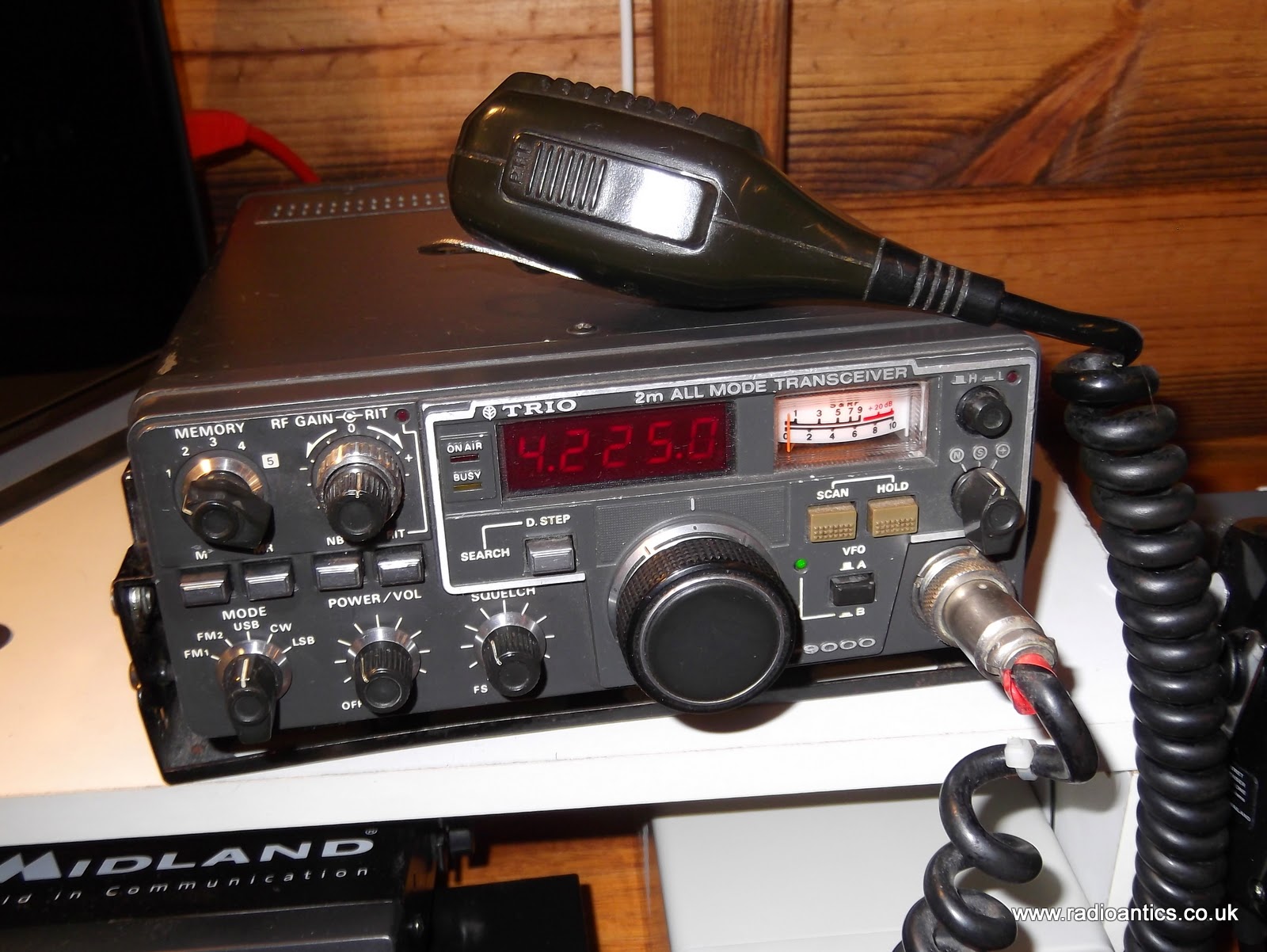
The TR9000 is a lovely compact rig, the case has the odd scuff but the front is in good condition and has cleaned up nicely. I just need to attend to the microphone plug as it wearing the ubiquitous piece of brightly coloured insulating tape. It is fully functional and I made a few contacts on it during last nights 144MHz UKAC. It is nice sounding and seems to have a good sensitive receiver.
The troublesome TR9500 has been back on the bench and connected to a dummy load and my X-50 dual-band collinear and I cannot find anything wrong. The ALC 'issue' I suspected was a red-herring, the audio does cuts out and the S-meter goes to S9 but only when the RF gain knob is turned to minimum not maximum as I'd thought, the same thing happens on the TR9000.
It is entirely possible the fault reported by its previous owner is intermittent (a bad joint, sticky relay etc) It is also a possibility that RF was leaking back in the rig causing it to lock up. I plan to use it in anger maybe during next weeks 432MHz UKAC especially if the receiver proves as sensitive as that in the TR9000.
As I mentioned the National Hamfest took place recently and since it is local to me I decided to go along on both days. The Friday was by far the busier day with lots of sellers in the outdoor flea-market with a genuine 'buzz' which seemed lacking on the Saturday, there were a lot less sellers outdoors.
The main hall left me a bit underwhelmed, the layout seemed a bit messy and some areas were cramped while others seemed to have acres of spare room. It was also very hot in the main hall especially on the busy Friday, however it was still an enjoyable couple of days and met up with some fellow tweeters and operators.
My purchases were modest and as well as the usual connectors and cabling I picked up a nice as-new 7A regulated linear power supply, a foot switch, a replacement satellite Quad-LNB, a very sorry looking 70cm linear amplifier and picked up one of those lovely Czech morse-keys for when I brave doing the code!
I also picked up this little 2.4GHz B/W video monitor for a whopping £1 and it works a treat. I have a number of 2.4GHz wireless security cameras (purchased back in 2009) intended for a PC-based PVR CCTV system but the whole PC system proved unreliable so they are sitting idle. This little monitor can receive on the four standand channels and as a bonus runs off 13.8V so ideal for sticking in the car and driving around the local housing estate eavesdropping on other similar cameras - I am joking of course!
The very sorry looking 70cm linear amplifier is a Tokyo Hy-Power HL-60U. I found it hiding away in a box of junk on one stall and after a bit of haggling got it for a fiver! From its appearance I really didn't expect it work, especially since the warranty seal had been broken. I wasn't too bothered about the power amplifier I was far more interested if the built in GaAsFET pre-amplifier still worked.

Getting it on the bench I opened the case, expecting to find it plundered and butchered and was pleasantly surprised to find the insides looked almost pristine. I think the main PA transistor may have been replaced, but while it looks a bit messy the flux resin around its joints looks the same as other areas of the PCB so not sure. It looks slightly different internally to some another photographs I found on line and I have searched the web for a manual and schematic with no joy. Tokyo Hy-Power went bankrupt last year and the website and precious data downloads have all but disappeared.

As it looked intact with nothing missing I connected up the dummy load, power meter and fed the input from one of my Baofeng handhelds. It powered up and was giving 15W out for a measured 3W in with no distortion on the audio, so far so good. However after connecting up the FT-857D and slowly increasing the input power is became apparent that 15W seemed to be about the limit of its output, not the 60W as promised.
Removing the dummy load and putting it on the X-50 antenna I had a listen around for weak stations to checked the operation of receive pre-amp and it worked! Should prove useful for the 70cm contests.
It is the Trio/Kenwood TR9500 that I repaired last month for a fellow club member. Having no transmit audio I'd replaced a faulty transistor in the microphone pre-amp. Subsequently it's owner reported it was still misbehaving and locking up in transmit mode.
I'd offered to give it another look but the owner decided to cut his losses and wanted shot of it. He had just purchased a nice new radio at the National Hamfest and was also selling a 2m Trio/Kenwood TR9000 multi-mode set to make some room.
I liked the look of these pretty sisters and got both of them for a very reasonable price, the TR9500 costing just £10 in lieu of the previous repair work. I collected them at the weekend and got around to checking them out last night.
The TR9000 is a lovely compact rig, the case has the odd scuff but the front is in good condition and has cleaned up nicely. I just need to attend to the microphone plug as it wearing the ubiquitous piece of brightly coloured insulating tape. It is fully functional and I made a few contacts on it during last nights 144MHz UKAC. It is nice sounding and seems to have a good sensitive receiver.
The troublesome TR9500 has been back on the bench and connected to a dummy load and my X-50 dual-band collinear and I cannot find anything wrong. The ALC 'issue' I suspected was a red-herring, the audio does cuts out and the S-meter goes to S9 but only when the RF gain knob is turned to minimum not maximum as I'd thought, the same thing happens on the TR9000.
It is entirely possible the fault reported by its previous owner is intermittent (a bad joint, sticky relay etc) It is also a possibility that RF was leaking back in the rig causing it to lock up. I plan to use it in anger maybe during next weeks 432MHz UKAC especially if the receiver proves as sensitive as that in the TR9000.
As I mentioned the National Hamfest took place recently and since it is local to me I decided to go along on both days. The Friday was by far the busier day with lots of sellers in the outdoor flea-market with a genuine 'buzz' which seemed lacking on the Saturday, there were a lot less sellers outdoors.
The main hall left me a bit underwhelmed, the layout seemed a bit messy and some areas were cramped while others seemed to have acres of spare room. It was also very hot in the main hall especially on the busy Friday, however it was still an enjoyable couple of days and met up with some fellow tweeters and operators.
My purchases were modest and as well as the usual connectors and cabling I picked up a nice as-new 7A regulated linear power supply, a foot switch, a replacement satellite Quad-LNB, a very sorry looking 70cm linear amplifier and picked up one of those lovely Czech morse-keys for when I brave doing the code!
I also picked up this little 2.4GHz B/W video monitor for a whopping £1 and it works a treat. I have a number of 2.4GHz wireless security cameras (purchased back in 2009) intended for a PC-based PVR CCTV system but the whole PC system proved unreliable so they are sitting idle. This little monitor can receive on the four standand channels and as a bonus runs off 13.8V so ideal for sticking in the car and driving around the local housing estate eavesdropping on other similar cameras - I am joking of course!
The very sorry looking 70cm linear amplifier is a Tokyo Hy-Power HL-60U. I found it hiding away in a box of junk on one stall and after a bit of haggling got it for a fiver! From its appearance I really didn't expect it work, especially since the warranty seal had been broken. I wasn't too bothered about the power amplifier I was far more interested if the built in GaAsFET pre-amplifier still worked.
Getting it on the bench I opened the case, expecting to find it plundered and butchered and was pleasantly surprised to find the insides looked almost pristine. I think the main PA transistor may have been replaced, but while it looks a bit messy the flux resin around its joints looks the same as other areas of the PCB so not sure. It looks slightly different internally to some another photographs I found on line and I have searched the web for a manual and schematic with no joy. Tokyo Hy-Power went bankrupt last year and the website and precious data downloads have all but disappeared.
As it looked intact with nothing missing I connected up the dummy load, power meter and fed the input from one of my Baofeng handhelds. It powered up and was giving 15W out for a measured 3W in with no distortion on the audio, so far so good. However after connecting up the FT-857D and slowly increasing the input power is became apparent that 15W seemed to be about the limit of its output, not the 60W as promised.
Removing the dummy load and putting it on the X-50 antenna I had a listen around for weak stations to checked the operation of receive pre-amp and it worked! Should prove useful for the 70cm contests.
Repairing a Kenwood TR9500, Part2 – TX working, SSB RX not
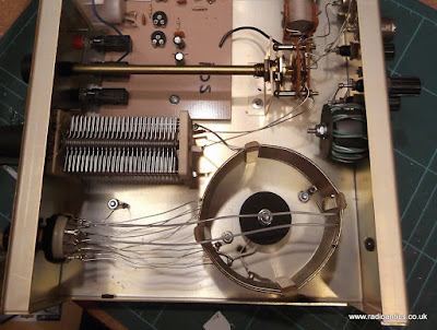
As I suspected the microphone amplifier Q1 in the Kenwood/Trio TR9500 was indeed faulty. The replacement arrived next day and within an hour I had successfully soldered in the new 2SC2240 transistor and it now had audio on transmit.
Transmitting into a dummy load and monitoring on my FT857-D the FM transmission was fine, the SSB was okay, perhaps slightly over driven. I suspected that maybe the previous owner might have twiddled something to compensate for a failing Q1.
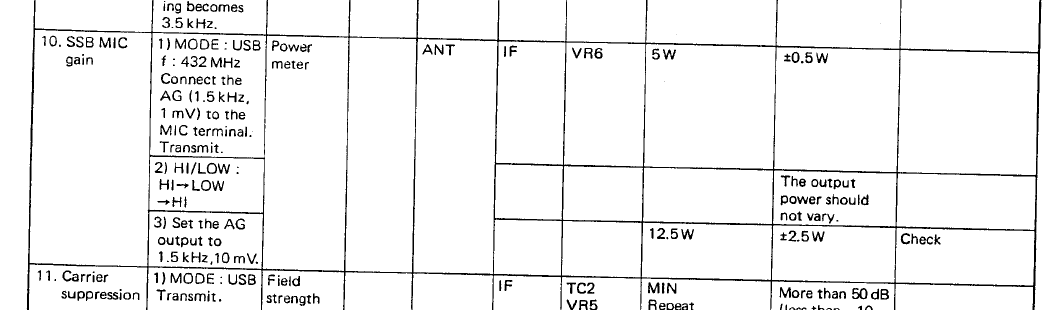
In the adjustments section of the service manual VR6 on the IF unit controls the SSB MIC gain. To check the settings it was a case of setting the transmitter to 432MHz and putting an audio frequency signals of 1.5kHz of amplitude 1mV and 10mV from my signal generator on to the microphone terminal, and observing the RF power output, which were the 5W and just over 10W as required. As this didn't need altering I left it alone and boxed it back up and returned it to the happy owner.
Last night was the RSGB 432MHz UKAC Contest and I was hoping to here it on the air, sadly I didn't. It now transpires that there maybe another issue with it, something I should have spotted.
I do remember something strange when doing the initial testing. Connected to a dummy load and in SSB mode the S-meter showed S9+ when in receive but with no audio, turning the RF gain control the meter dropped to S0 and normal white noise static could be heard. It received a SSB transmission from the FT857-D with no issue so I thought no more of it. Being over eager and not experienced with using different rigs I had mistakenly dismissed it and should really have read the operating manual more extensively.
The anomalous S9+ meter reading and no audio occured when the RF gain control was set to the maximum which is the normal recommended setting for operating, I'd simply turned the RF gain control to the minimum mitigating the issue.
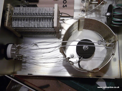
Obviously the rigs owner had put the RF gain back to maximum and was now reporting it wasn't switching back to receive. In fact it is but nothing is being heard. Checking the service manual this morning and it appears there is an issue with the AGC circuit (description and block diagram below)

It seems the rig may well find itself back on the bench, however this repair could be more problematic!
As I mentioned it was the 432MHz UKAC last night and I had a decent night of search and pounce. Conditions were very strange, lots of fading and strangely some of the usual local operators were not heard. I was very pleased to catch some lift and made a couple of decent DX contacts in Northern Ireland, The Isle of Man, Northumberland as well as Essex and Cambridge.
Transmitting into a dummy load and monitoring on my FT857-D the FM transmission was fine, the SSB was okay, perhaps slightly over driven. I suspected that maybe the previous owner might have twiddled something to compensate for a failing Q1.
In the adjustments section of the service manual VR6 on the IF unit controls the SSB MIC gain. To check the settings it was a case of setting the transmitter to 432MHz and putting an audio frequency signals of 1.5kHz of amplitude 1mV and 10mV from my signal generator on to the microphone terminal, and observing the RF power output, which were the 5W and just over 10W as required. As this didn't need altering I left it alone and boxed it back up and returned it to the happy owner.
Last night was the RSGB 432MHz UKAC Contest and I was hoping to here it on the air, sadly I didn't. It now transpires that there maybe another issue with it, something I should have spotted.
I do remember something strange when doing the initial testing. Connected to a dummy load and in SSB mode the S-meter showed S9+ when in receive but with no audio, turning the RF gain control the meter dropped to S0 and normal white noise static could be heard. It received a SSB transmission from the FT857-D with no issue so I thought no more of it. Being over eager and not experienced with using different rigs I had mistakenly dismissed it and should really have read the operating manual more extensively.
The anomalous S9+ meter reading and no audio occured when the RF gain control was set to the maximum which is the normal recommended setting for operating, I'd simply turned the RF gain control to the minimum mitigating the issue.
Obviously the rigs owner had put the RF gain back to maximum and was now reporting it wasn't switching back to receive. In fact it is but nothing is being heard. Checking the service manual this morning and it appears there is an issue with the AGC circuit (description and block diagram below)
RECEIVER CIRCUIT
.... The signal is picked up from the last stage of the IF amplifier (Q23), then detected and amplified to generate the AGC voltage. The AGC time constant is automatically set according to the mode : FAST for CW; SLOW for SSB. The AGC voltage is applied to IF amplifiers Q21, Q22 and Q23 (3SK73(GR)) and RF amplifier Q51. It is also used to drive the S meter.
It seems the rig may well find itself back on the bench, however this repair could be more problematic!
As I mentioned it was the 432MHz UKAC last night and I had a decent night of search and pounce. Conditions were very strange, lots of fading and strangely some of the usual local operators were not heard. I was very pleased to catch some lift and made a couple of decent DX contacts in Northern Ireland, The Isle of Man, Northumberland as well as Essex and Cambridge.
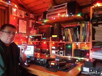
Who needs a preamp on 432MHz with ears as good as mine? Well actually I do desperately! #ukac pic.twitter.com/WXnMBGY0uw
— Andrew Garratt (@nerdsville) September 9, 2014 In a few weekends it is the National Hamfest, which is held in my home town and I hoping to pick up some bargain gear to improve my UHF set up, however from past experience that may prove difficult.