Author Archive
 MiniTiouner DATV Receiver built
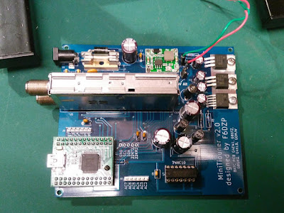
At the weekend I built my MiniTiouner DATV receiver. I'd purchased the PCB, tuner module, 1V regulator and programmed USB interface module from the BATC stand at the Telford ATV Academy the previous weekend. The remaining components that I didn't already have were ordered from Digikey using the handy spreadsheet on the BATC Wiki and I sourced a suitable DC-DC Converter from eBay.
The build was straightforward and there are some instructions by Mike G0MJW but only really referenced them for the commissioning stage, checking voltages etc. I was pleasantly surprised to see a large degree of protection on the board, fuses both filament and poly-fuse, reverse protection and zener diodes in the circuit.
The MiniTiouner uses free to download DVB-S receive and analysis software called "Minitioune" written by F6DZP. The Software is hosted on the VivaDATV forum. So I registered and downloaded the software.
V8.0 of the software requires a pull-down resistor adding to the USB module to identify the type of board, so that was added (not pictured).
Power was connected and then plugged the USB lead into the PC (Windows 7 32bit) and it went off and installed drivers. The documentation said I should see two USB controllers, but I was seeing four?
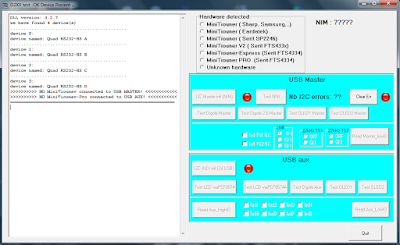
There are several test programs included in the software package to test drivers and board and they were showing errors.

The PC I was using has had no end of serial USB devices plugged in and out over time so suspecting another Microsoft Windows "disappearing up its own backside" driver issue I tried it on another more vanilla machine but had the same problem.
This seemed to point to the USB interface (an FTDI FT2232H Mini Module) perhaps it wasn't programmed? So I downloaded the FTProg utility from FTDI but instead of seeing a FT2232H was showing it as a FT4232H device.
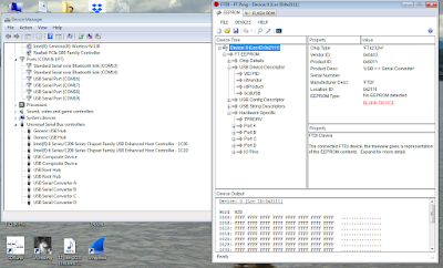
Doing a Google found a reference to the same problem. I downloaded the data-sheet and checking with a meter I could see pins CN2-5 and CN2-11(VIO) on the module didn't have 3.3V for some reason and as the post said if the VIO pin is missing 3.3V it defaults to a FT4232H. In the end I checked my soldering (no fault found) I removed the module from the socket to examine it and after re-seating it the board sprang to life so seems it was just a bad connection.
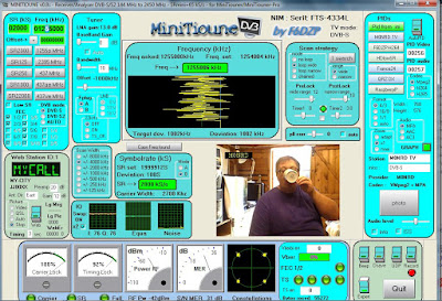
Eager to test I set up the ADALM-PLUTO SDR running DATVExpress as I'd done previously with the commercial set-top satellite receiver and we had a picture! It was time for a cup of tea!
Now it was working all that was left was to put it in a box.

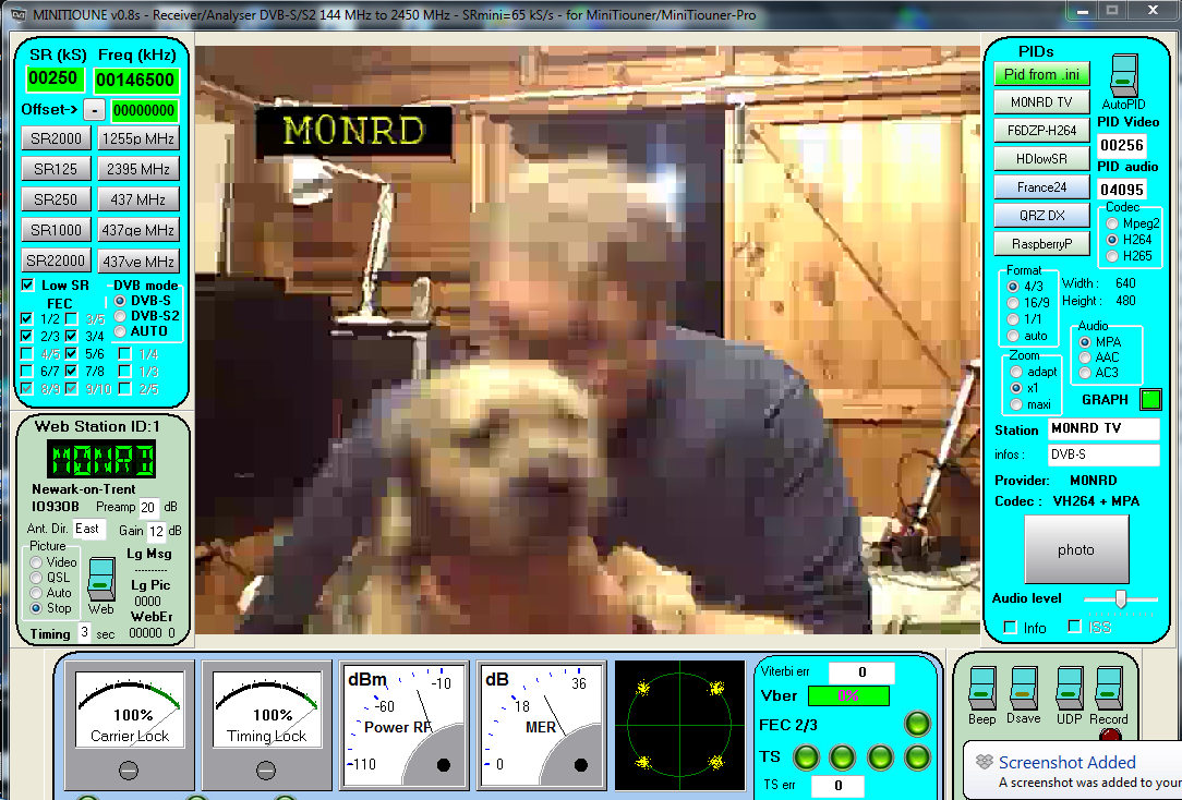
I have only had a brief play with the software since the weekend but was interested to see if I could receive some RB-TV (Reduced bandwidth) So I set the Pluto and DATVExpress to transmit on 146.500MHz using a low symbol rate (250 Ksymbols/s) and it worked! Bertie was wriggling a bit too much for a clear picture but I had now actually used my 146-147MHz NoV. Now just got to learn and understand the various modulations and settings.

I was able to try out another piece of software, the Spectrum Analyser from Steve Andrew for the SDRPlay. It turns the SDR receiver into a handy spectrum analyser with 10MHz bandwidth from 1kHz upto 2GHz and was able to check the output of the Pluto.
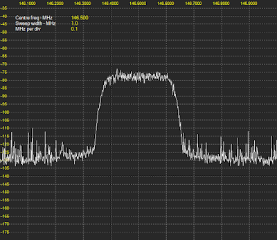
This wasn't a proper test setup by any means, the SDRPlay was still connected to the dual-band collinear outside the shack so the noise is the usual hash I see, but the Pluto was putting out a decent waveform, it did help putting on a proper resonant antenna (a spare mobile magmount) rather than the tiny one supplied.
I plan to do a bit more with the 5.6GHz FPV stuff before the weekend having took delivery of some nice grid antennas and hope to get out to try a contact or some tests with members of SKARS 73
The build was straightforward and there are some instructions by Mike G0MJW but only really referenced them for the commissioning stage, checking voltages etc. I was pleasantly surprised to see a large degree of protection on the board, fuses both filament and poly-fuse, reverse protection and zener diodes in the circuit.

The MiniTiouner uses free to download DVB-S receive and analysis software called "Minitioune" written by F6DZP. The Software is hosted on the VivaDATV forum. So I registered and downloaded the software.
V8.0 of the software requires a pull-down resistor adding to the USB module to identify the type of board, so that was added (not pictured).
Power was connected and then plugged the USB lead into the PC (Windows 7 32bit) and it went off and installed drivers. The documentation said I should see two USB controllers, but I was seeing four?
There are several test programs included in the software package to test drivers and board and they were showing errors.
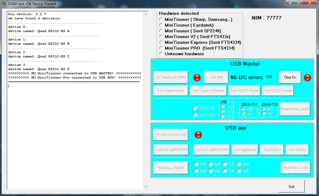

The PC I was using has had no end of serial USB devices plugged in and out over time so suspecting another Microsoft Windows "disappearing up its own backside" driver issue I tried it on another more vanilla machine but had the same problem.
This seemed to point to the USB interface (an FTDI FT2232H Mini Module) perhaps it wasn't programmed? So I downloaded the FTProg utility from FTDI but instead of seeing a FT2232H was showing it as a FT4232H device.
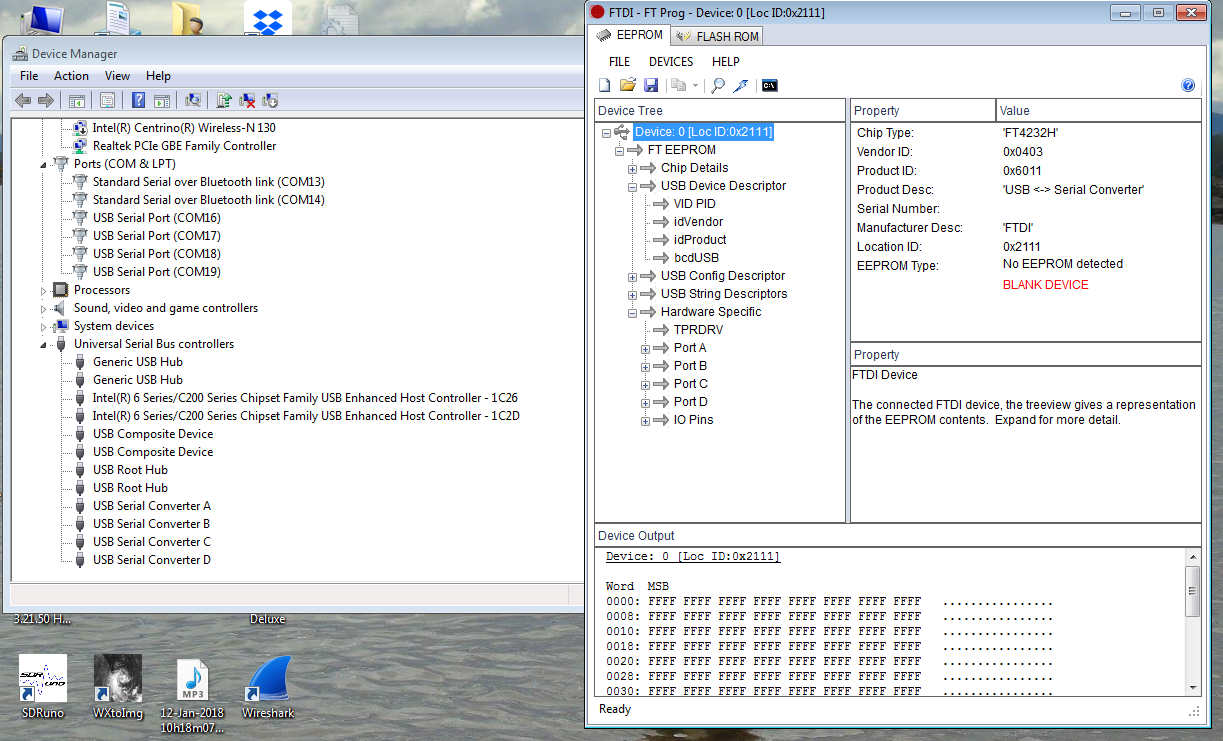
Doing a Google found a reference to the same problem. I downloaded the data-sheet and checking with a meter I could see pins CN2-5 and CN2-11(VIO) on the module didn't have 3.3V for some reason and as the post said if the VIO pin is missing 3.3V it defaults to a FT4232H. In the end I checked my soldering (no fault found) I removed the module from the socket to examine it and after re-seating it the board sprang to life so seems it was just a bad connection.
Eager to test I set up the ADALM-PLUTO SDR running DATVExpress as I'd done previously with the commercial set-top satellite receiver and we had a picture! It was time for a cup of tea!

Now it was working all that was left was to put it in a box.

I have only had a brief play with the software since the weekend but was interested to see if I could receive some RB-TV (Reduced bandwidth) So I set the Pluto and DATVExpress to transmit on 146.500MHz using a low symbol rate (250 Ksymbols/s) and it worked! Bertie was wriggling a bit too much for a clear picture but I had now actually used my 146-147MHz NoV. Now just got to learn and understand the various modulations and settings.
I was able to try out another piece of software, the Spectrum Analyser from Steve Andrew for the SDRPlay. It turns the SDR receiver into a handy spectrum analyser with 10MHz bandwidth from 1kHz upto 2GHz and was able to check the output of the Pluto.
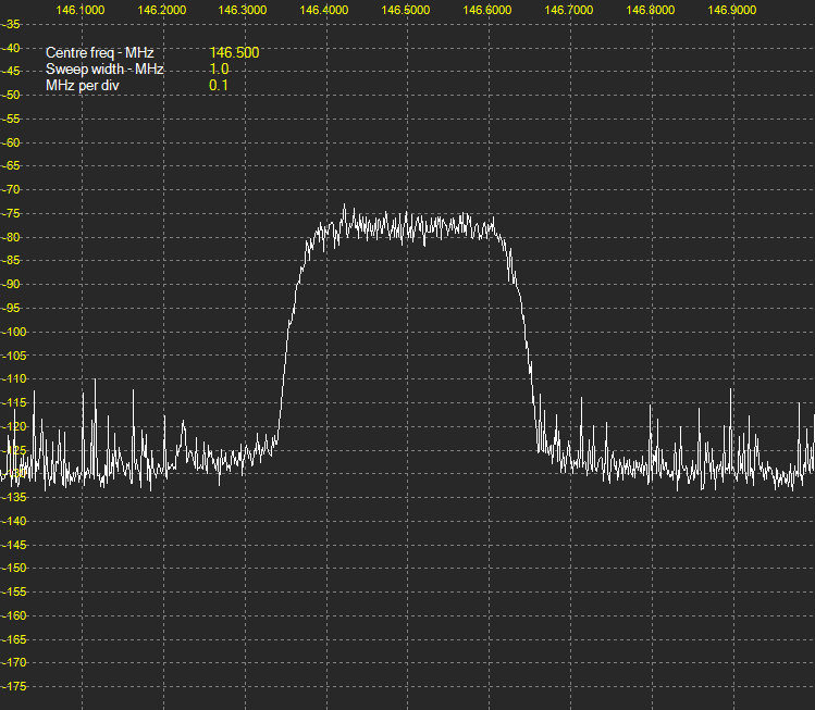
This wasn't a proper test setup by any means, the SDRPlay was still connected to the dual-band collinear outside the shack so the noise is the usual hash I see, but the Pluto was putting out a decent waveform, it did help putting on a proper resonant antenna (a spare mobile magmount) rather than the tiny one supplied.
I plan to do a bit more with the 5.6GHz FPV stuff before the weekend having took delivery of some nice grid antennas and hope to get out to try a contact or some tests with members of SKARS 73
Moving Pictures! First dabbles in Amateur TV
I am always keen to try something new and I've spent the last couple of weeks experimenting with some Amateur Television ATV and Digital ATV (warning this post is bit of ramble and information overload)
They say "a picture paints a thousand words"and I've always liked the idea of sending pictures via radio having dabbled with sending and receiving SSTV and SSDV, including pictures from High Altitude Balloons (HABs) like the Hamfest HAB flight I did back in 2015

But I've also been intrigued by "Fast scan TV" to transmit moving images. I've seen demonstrations at conferences and in online videos and joined the British Amateur Television Club BATC a few years ago but apart from reading the CQ-TV magazine I had not done anything mainly due to expense and investment I mistakenly thought I would need to make.
Recently I have seen mention of using easy and low cost equipment to get on the air on 5.6GHz (the 6 cm amateur band) using cheap modules intended to transmit “First Person Video” (FPV) back from drones.
These simple units can be used without any modifications to get on air. A number of operators have used them with high gain WiFi panel and/or dish antennas with a clear line of sight path to send pictures to stations using the same equipment over paths in excess of 50km, the current record is over 160km. Chris Leviston M0KPW has an excellent website describing his 5.6GHz system http://www.5-6ghz-atv.co.uk/ and there is more information at the BATC Wiki https://wiki.batc.org.uk/5.6_GHz
Inspired I ordered some kit from eBay a few weeks back, a receiver module and transmitter arrived quite quickly (no slow boat from China this time)
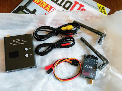
The equipment is powered by a 12V supply and input and output is a composite video signal and audio. It can be fed by a standard camera or video source but I dug out an old Raspberry Pi and soon had it generating and transmitting a test card with the required call sign overlay. The modules are channelised, the displayed 33 number is bank 3, channel 3 which is 5.665GHz selected by the BATC since it sits inside the amateur allocation,
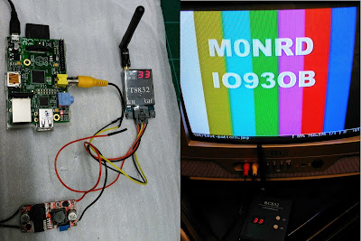
Over the week I refined the Pi software, adding the Pi camera and various libraries in python to generate video with informational overlay, adding a GPS allowed calculation of the locator square when out portable. I have put it in a box (sorry no picture of that) and a switch to flip between live video and test card. I also had a bash at making some double biquad antennas. Regularly updating my twitter feed with various milestones (I recommend you follow me)
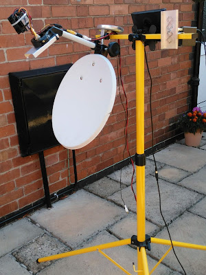 The satellite dish is inverted because they are offset so when the dish is vertical they are actually pointing around 20 degrees upward towards the TV satellite (in the UK). So for terrestrial use with low elevation they work better inverted. (see here for better description of offset dishes)
 I did venture out but I chickened out setting up due to a combination of a surprisingly busy road, fly tipping and very hot conditions. Due to the the fly tipping in the lay-by I didn't want to be seen getting stuff out of car boot! especially as a few cars had slowed down as they passed.
Nevermind I have ordered couple of cheap high-gain mesh dish antennas so when they arrive I will get out again and arrange some skeds, hopefully roping in some of the radio club.
In addition to the 5.6GHz stuff I have also taken possession of an ADALM-PLUTO SDR from Analog Devices. It is inexpensive (£90/$100) and designed to allow educational experimenting in software defined radio. It is a SDR receiver and low-power transmitter. They had been in short supply but availability has improved.
Charles Brain G4GUO has added support for the device into the DATV Express software. I am hoping to use it for some experiments in RB-TV (Reduced bandwidth TV) so I can actually use my NoVs
I took the PLUTO along to the ATV workshop and was able to see it transmitting and being received by other peoples receivers. So last night I got out the two satellite receivers I have and with a little bit of persuasion with settings got some DVB-S DATV transmitted and received.
They say "a picture paints a thousand words"and I've always liked the idea of sending pictures via radio having dabbled with sending and receiving SSTV and SSDV, including pictures from High Altitude Balloons (HABs) like the Hamfest HAB flight I did back in 2015

But I've also been intrigued by "Fast scan TV" to transmit moving images. I've seen demonstrations at conferences and in online videos and joined the British Amateur Television Club BATC a few years ago but apart from reading the CQ-TV magazine I had not done anything mainly due to expense and investment I mistakenly thought I would need to make.
Recently I have seen mention of using easy and low cost equipment to get on the air on 5.6GHz (the 6 cm amateur band) using cheap modules intended to transmit “First Person Video” (FPV) back from drones.
These simple units can be used without any modifications to get on air. A number of operators have used them with high gain WiFi panel and/or dish antennas with a clear line of sight path to send pictures to stations using the same equipment over paths in excess of 50km, the current record is over 160km. Chris Leviston M0KPW has an excellent website describing his 5.6GHz system http://www.5-6ghz-atv.co.uk/ and there is more information at the BATC Wiki https://wiki.batc.org.uk/5.6_GHz
Inspired I ordered some kit from eBay a few weeks back, a receiver module and transmitter arrived quite quickly (no slow boat from China this time)

The equipment is powered by a 12V supply and input and output is a composite video signal and audio. It can be fed by a standard camera or video source but I dug out an old Raspberry Pi and soon had it generating and transmitting a test card with the required call sign overlay. The modules are channelised, the displayed 33 number is bank 3, channel 3 which is 5.665GHz selected by the BATC since it sits inside the amateur allocation,
Over the week I refined the Pi software, adding the Pi camera and various libraries in python to generate video with informational overlay, adding a GPS allowed calculation of the locator square when out portable. I have put it in a box (sorry no picture of that) and a switch to flip between live video and test card. I also had a bash at making some double biquad antennas. Regularly updating my twitter feed with various milestones (I recommend you follow me)
Pi sending live video via 5.6GHz with text overlay using pi camera and raspivid easy peasy.. pic.twitter.com/Fthfpbw0r0— Andrew Garratt M0NRD (@nerdsville) July 28, 2018
While browsing the BATC website for information I spotted that there was an ATV Academy workshop being organised by the Telford and District ARS, giving people the opportunity of finding out a bit more about ATV and people could bring along their equipment and projects for advice. So at the last minute I decided to go but because of the distance could only really go on the Saturday. But it was well worth it and a great day. I was made to feel welcome by everyone there and was able to show off my modest achievements on 5.6GHz and learned about the BATC Portsdown Transceiver and MiniTioune receiver projects, even buying the parts to build the receiver.Lol, wife looking suitably impressed by the Pi based image generator which flips between live feed and test card using switch pic.twitter.com/M6qnif5V0P— Andrew Garratt M0NRD (@nerdsville) August 3, 2018
The academy coincided with a BATC Activity weekend and they were going up to the summit of the nearby Long Mynd to operate on the Sunday. Since I wasn't there I had planned to go to a local high point to see if I could make contact with some of the other operators and stations and got the kit ready on a cheap lighting tripod. I was going to use an old portable satellite dish with one of my double biquads at the feed point.Having a great time learning all about ATV today, showing off my humble efforts pic.twitter.com/YTwEf7Sjdl— Andrew Garratt M0NRD (@nerdsville) August 4, 2018


Nevermind I have ordered couple of cheap high-gain mesh dish antennas so when they arrive I will get out again and arrange some skeds, hopefully roping in some of the radio club.
In addition to the 5.6GHz stuff I have also taken possession of an ADALM-PLUTO SDR from Analog Devices. It is inexpensive (£90/$100) and designed to allow educational experimenting in software defined radio. It is a SDR receiver and low-power transmitter. They had been in short supply but availability has improved.
Charles Brain G4GUO has added support for the device into the DATV Express software. I am hoping to use it for some experiments in RB-TV (Reduced bandwidth TV) so I can actually use my NoVs
I took the PLUTO along to the ATV workshop and was able to see it transmitting and being received by other peoples receivers. So last night I got out the two satellite receivers I have and with a little bit of persuasion with settings got some DVB-S DATV transmitted and received.
Anyway, that is enough for now.. but will try to keep the blog updated as I experiment some more, but follow my twitter account @nerdsville for realtime updates 73 AndrewBit of "shaky cam" but shows the ADALM-PLUTO transmitting across the shack using #DATVExpress being received by an old FTA satellite box. pic.twitter.com/souCJA9qBK— Andrew Garratt M0NRD (@nerdsville) August 5, 2018
In The Loop! – First Impressions of the MFJ-1788
Was feeling pretty chuffed after repairing the MFJ-1788 'Super Loop' and couldn't wait to try it out! So for a couple of evenings of experimenting I put the loop in the garden on a 5ft pole held up by a heavy drive-on stand with 20m (65ft) of RG58 running into the shack.
I chose the easy option of using FT8 to do some testing, selecting the 30m FT8 frequency initially. I tuned the loop and was met with a cacophony of signals, far louder than my usual OCFD would receive. Working with around 30 Watts had a few contacts in a brief 30 minute session, including a nice one in Greece with SV1IW.
What was striking was the lack of noise and just how tight the tuning was, indeed I had to tweak the tuning a couple of times during tests, a slight adjustment either way and the signals just disappeared. I checked out 40m and 20m as well with similar good results.
I had a few more sessions and a few days later I tried it out to receive the Shortwave Radiogram broadcast from Bulgaria on 9400kHz, this time as it was a broadcast band had to use my ear to do the tuning, adjusting till I heard a rise in 'noise' and signal.
I am very happy with the loop. Transmission wise it unsurprisingly doesn't seem a huge improvement over the OCFD on its resonant bands, it scores over the OCFD is on its 'non-resonant' bands such as 30m and 17m. But the massive improvement is in receiving, signals are stronger and noise is much lower, picking up some more distance signals even given the poor conditions.
I also have had issues trying to operate the radio remotely, I have tuned it up on an FT8 frequency in the morning and then later in the day logged in to try to make a few QSOs during a coffee-break to see the loop has drifted out of resonance. This can only be down to the loop getting warm in the summer sun.
I am still evaluating the antenna but am looking at making a better controller, over on AmateurRadio.com where this blog is syndicated, I have had a number of kind comments including one from Elwood Downey, WB0OEW who pointed me to his published design of a controller, using a similar method to what I was toying with. Thanks Elwood.
73 for now, more updates soon.
 |
| Temporary test setup |
 |
| PSKReporter showing where I was spotted |
I had a few more sessions and a few days later I tried it out to receive the Shortwave Radiogram broadcast from Bulgaria on 9400kHz, this time as it was a broadcast band had to use my ear to do the tuning, adjusting till I heard a rise in 'noise' and signal.
I have now got the loop up on a rotator and mounted slightly higher up with a shorter length of RG213 (not on the video) it is still quite low and unfortunately is slightly shielded to the south by the neighbours metal roofed building,Trying out the loop antenna, @SWRadiogram— Andrew Garratt (@nerdsville) May 19, 2018
images this afternoon from Bulgaria 9400kHz pic.twitter.com/53HRwIHUQz
I am very happy with the loop. Transmission wise it unsurprisingly doesn't seem a huge improvement over the OCFD on its resonant bands, it scores over the OCFD is on its 'non-resonant' bands such as 30m and 17m. But the massive improvement is in receiving, signals are stronger and noise is much lower, picking up some more distance signals even given the poor conditions.
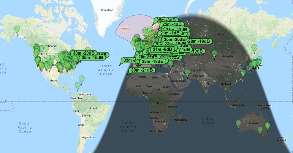
The antenna cannot be said to be a pretty thing to have in the garden! The tuning is very particular, in the video I show the 'auto tuning' isn't ideal. It requires the radio to be putting out a signal into a mismatched load for what could be nearly a minute. Not good for the radio and is a source of QRM during this time, the usual technique of tuning slightly off a QSO frequency is more problematic due to the sharpness of the resonance. You can still tune off frequency and then tweak with the slow tune buttons to bring it in. I've noticed that on some of the higher bands it occasionally doesn't auto-tune because the 'dip' seems very short/sharp and the controller doesn't react in time and overshoots especially using low power settings.still evaluating the RX of the mag-loop and according to pskreporter heard 92 countries, 1182 stations on FT8 30m/40m in the last 17 hours.. pic.twitter.com/ZuWZOFFiP2— Andrew Garratt (@nerdsville) May 22, 2018
I also have had issues trying to operate the radio remotely, I have tuned it up on an FT8 frequency in the morning and then later in the day logged in to try to make a few QSOs during a coffee-break to see the loop has drifted out of resonance. This can only be down to the loop getting warm in the summer sun.
I am still evaluating the antenna but am looking at making a better controller, over on AmateurRadio.com where this blog is syndicated, I have had a number of kind comments including one from Elwood Downey, WB0OEW who pointed me to his published design of a controller, using a similar method to what I was toying with. Thanks Elwood.
73 for now, more updates soon.
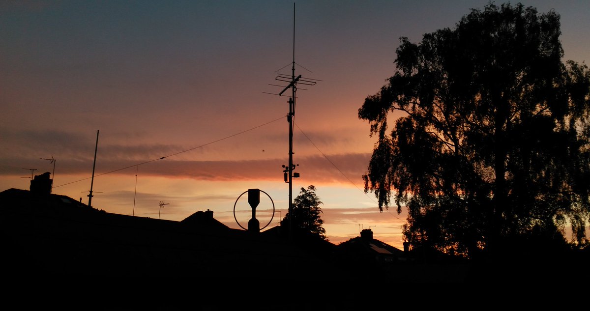 |
| The antenna farm |
In The Loop! – Repairing a MFJ-1788
Over the last few years I've seen various musings about magnetic loop antennas and their supposed efficiency and performance. I had even toyed with the idea of building one considering the eye-watering prices commercial ones are sold for! Sadly that idea had been added to the big pile of 'to-do' projects.
Earlier this year I spotted a posting on social media by a member of my club who had brought a MFJ-1788 second hand who was having issues with it not working. I had offered some advice on its repair and glibly offered to take it off his hands should he want to dispose of it. A few months later I got a message asking if I was still interested? I certainly was at the price he wanted.
I collect it at the club meeting a fortnight ago still with a 5ft pole still attached as a bonus! Thankfully it fitted in the car (just).
I downloaded the manual and schematic from the MFJ website and I saw there were conspicuous warnings about using an 'isolated' power supply both in the manual and on the back of the controller, with ominous warnings of damage if you didn't. Most shack supplies have the negative/black pin connected to the chassis/ground.
The controller had come to me supplied with a standard fused lead, you know the ones that come to connect your ATU/SWR meter lamp to the shack supply? Mmmm.. my spider sense was tingling!
I pulled out a small double-insulated 12V plug-in supply from my collection (you can spot them as they often have a plastic earth pin) and with nothing else connected powered up the controller. The meter lamp came on and some of the LEDS briefly flickered and heard a few clicks from the internal buzzer then nothing. Pressing buttons did nothing and then I caught the unmistakable scent of burning electronics!
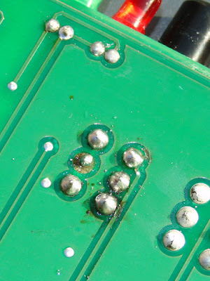
Opening the box up on the bench quickly spotted the source, the regular had well and truly smoked, but since nothing had been connected the short must have been in the controller itself (and it was not the dodgy wires that look like they had been victims to a wayward soldering iron)

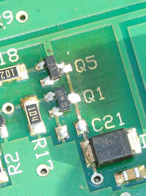
Inspecting the rest of the board it was clear that it had been repaired (badly) once before, the two main transistors/FETs (Q1/Q5) used to control the motor clearly showed signs of being replaced (misaligned and with tell-tale scorching from an hot air gun)
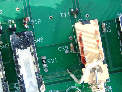
a SMD diode had been swapped and one of the 'fine tune' switches had been replaced, its removal had obviously been problematic taking with it some of the through hole copper and adjacent tracks which had been lifted/damaged.
Before opening up the box I had expected to see 'through hole' components and DIL logic ICs not for it to be all surface mounted. Undaunted I went through the parts list and decided to get replacements for all the semiconductor parts not knowing at this stage what I would have to replace. Getting two of each device in some cases five or ten of each due to minimum order quantity, the staggering cost was £8 ($11) including postage!
While waiting for the parts to arrive I decided to check out the actual antenna head. I removed the plastic covering and attempted to extract it from the pole..
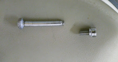
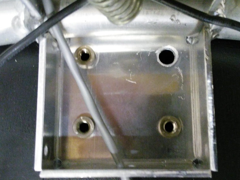
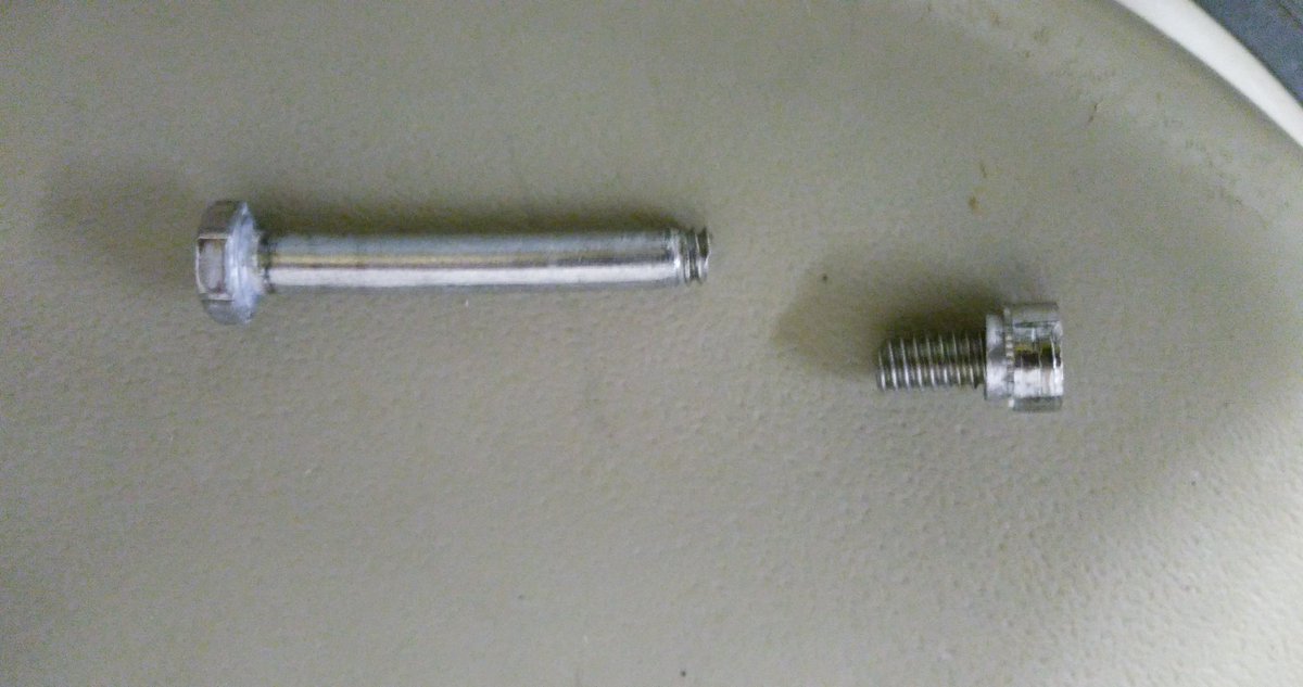
First issue I had was the mounting. One bolt had seized, the nut inserts are held in quite soft aluminium so not surprisingly the insert came out out the mounting when trying to remove it. Using grips to hold the insert the bolt still refused to turn and in the end it sheared off with very little force! Obviously quality fittings these!

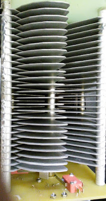
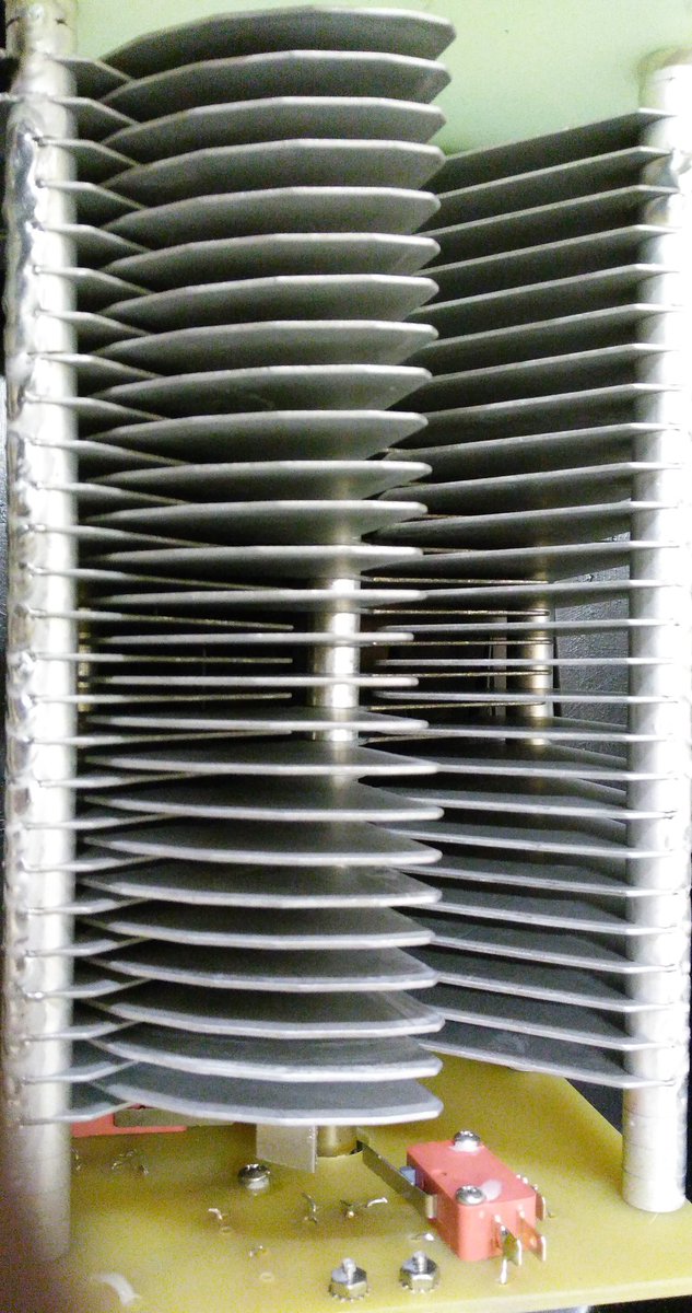
The variable capacitor was suffering a common problem due to poor quality control, the fins had gone out of alignment. Each fin is a separate assembly held on a shaft with a nut to compress them together. It is a simple fix, just realigned and tightened the bolt. The limit switches and motor connection were okay (another common problem) Applying a voltage to the coax connector the motor turned fine, reversing the voltage reversed the direction of turn, the vanes going fully in and fully out before the limit switches activated.
The components arrived prompty and so I got the hot air gun out and set about repairing the board.

I started off replacing the regulator (and the damaged power track) and Q1/Q5 and we had the flickering of life. Pressing the AUTO TUNE button the LED lit and there was 9V across the antenna connector, pressing the other AUTO TUNE button had -9V across. This is why you need an isolated power supply since it reverses the voltage to control direction. The radio doesn't see any of this voltage due to the bias-t arrangement. However if the supply shared the shack ground you would short out the supply, but the current would go via all those delicate electronics! Which is what I think had happened.
It soon became clear that most devices had suffered damage and so I ended up replacing the regulator 78L12, Q1 (SN7002 FET), Q2 (MMBT3906), Q5 (MMBT3906) all the logic ICs CMOS 4001, 4011 and 4066 and the LM324 Quad op-amp chip. I also gave the board a good clean since was covered in grime and flux residue.
Once I was happy the controller was reassembled and connected to my FT-857D on minimum power and the loop antenna propped up against the side of the shack. Success! I was able to successful tune it as per the instructions on 40m and 10m, the two extremes of operation and could here the telltale rise in receive noise as it became resonant.
I have yet to put the loop up in situ for a proper evaluation but have refurbished an old TV rotator to mount it on. I have fitted some nice new quality bolts. The black insulating tape round the loop has been removed, preferring the silver look myself.
Assuming it does performs and will find out this weekend, I have paid a total of £65 ($90) (£50 for the initial purchase the rest for replacement parts) which is an absolute bargain as to buy new it is expensive.. very expensive!
One of the main supplier in the UK, have it on sale for £699 ($940) but this includes their engineers inspecting and rebuilding each one before shipping! (Can only be due to poor build quality control and warranty claims) the RRP seems to be around £570 ($770)
It does amaze me how much this units costs new. While the loop construction is generally good, the mounting fittings appear to be poor and the issues with the capacitor and quality control are widely reported.
The components in the controller are not expensive, the switches, meter, box are the usual MFJ fare and the design is quite old (the PCB has copyright 1998 on the silk screen) the auto-tune process requires the radio to be putting RF into a mismatched load for up to a minute and even with low power and SWR protection this isn't good for the radio PA.
Perhaps most surprising is given the risk of damage due to incorrect use is why firstly the loop isn't supplied with a power supply anyway as they only cost a pittance and secondary why their isn't any protection built in? I intend fitting a simple 100mA fuse to offer some protection should a problem occurs.
If the loop performs it may be another project to build a better controller, there are a few designs out there on the internet using Arduino and DDS devices to create auto-tuners. Has that pile of potential projects just grows taller?
73 for now.. and promise to post a bit more regularly
Earlier this year I spotted a posting on social media by a member of my club who had brought a MFJ-1788 second hand who was having issues with it not working. I had offered some advice on its repair and glibly offered to take it off his hands should he want to dispose of it. A few months later I got a message asking if I was still interested? I certainly was at the price he wanted.
I collect it at the club meeting a fortnight ago still with a 5ft pole still attached as a bonus! Thankfully it fitted in the car (just).
 |
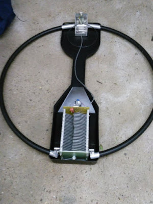
| Loop as purchased, with pvc tape covering loop |
 | |
| Control Box |
I downloaded the manual and schematic from the MFJ website and I saw there were conspicuous warnings about using an 'isolated' power supply both in the manual and on the back of the controller, with ominous warnings of damage if you didn't. Most shack supplies have the negative/black pin connected to the chassis/ground.
The controller had come to me supplied with a standard fused lead, you know the ones that come to connect your ATU/SWR meter lamp to the shack supply? Mmmm.. my spider sense was tingling!
I pulled out a small double-insulated 12V plug-in supply from my collection (you can spot them as they often have a plastic earth pin) and with nothing else connected powered up the controller. The meter lamp came on and some of the LEDS briefly flickered and heard a few clicks from the internal buzzer then nothing. Pressing buttons did nothing and then I caught the unmistakable scent of burning electronics!
Opening the box up on the bench quickly spotted the source, the regular had well and truly smoked, but since nothing had been connected the short must have been in the controller itself (and it was not the dodgy wires that look like they had been victims to a wayward soldering iron)

Inspecting the rest of the board it was clear that it had been repaired (badly) once before, the two main transistors/FETs (Q1/Q5) used to control the motor clearly showed signs of being replaced (misaligned and with tell-tale scorching from an hot air gun)
a SMD diode had been swapped and one of the 'fine tune' switches had been replaced, its removal had obviously been problematic taking with it some of the through hole copper and adjacent tracks which had been lifted/damaged.


Before opening up the box I had expected to see 'through hole' components and DIL logic ICs not for it to be all surface mounted. Undaunted I went through the parts list and decided to get replacements for all the semiconductor parts not knowing at this stage what I would have to replace. Getting two of each device in some cases five or ten of each due to minimum order quantity, the staggering cost was £8 ($11) including postage!
While waiting for the parts to arrive I decided to check out the actual antenna head. I removed the plastic covering and attempted to extract it from the pole..

First issue I had was the mounting. One bolt had seized, the nut inserts are held in quite soft aluminium so not surprisingly the insert came out out the mounting when trying to remove it. Using grips to hold the insert the bolt still refused to turn and in the end it sheared off with very little force! Obviously quality fittings these!
The variable capacitor was suffering a common problem due to poor quality control, the fins had gone out of alignment. Each fin is a separate assembly held on a shaft with a nut to compress them together. It is a simple fix, just realigned and tightened the bolt. The limit switches and motor connection were okay (another common problem) Applying a voltage to the coax connector the motor turned fine, reversing the voltage reversed the direction of turn, the vanes going fully in and fully out before the limit switches activated.
The components arrived prompty and so I got the hot air gun out and set about repairing the board.

I started off replacing the regulator (and the damaged power track) and Q1/Q5 and we had the flickering of life. Pressing the AUTO TUNE button the LED lit and there was 9V across the antenna connector, pressing the other AUTO TUNE button had -9V across. This is why you need an isolated power supply since it reverses the voltage to control direction. The radio doesn't see any of this voltage due to the bias-t arrangement. However if the supply shared the shack ground you would short out the supply, but the current would go via all those delicate electronics! Which is what I think had happened.
It soon became clear that most devices had suffered damage and so I ended up replacing the regulator 78L12, Q1 (SN7002 FET), Q2 (MMBT3906), Q5 (MMBT3906) all the logic ICs CMOS 4001, 4011 and 4066 and the LM324 Quad op-amp chip. I also gave the board a good clean since was covered in grime and flux residue.
Once I was happy the controller was reassembled and connected to my FT-857D on minimum power and the loop antenna propped up against the side of the shack. Success! I was able to successful tune it as per the instructions on 40m and 10m, the two extremes of operation and could here the telltale rise in receive noise as it became resonant.
I have yet to put the loop up in situ for a proper evaluation but have refurbished an old TV rotator to mount it on. I have fitted some nice new quality bolts. The black insulating tape round the loop has been removed, preferring the silver look myself.
 |
| Waiting to be put on the pole |
 |
| Shiny once again |
Assuming it does performs and will find out this weekend, I have paid a total of £65 ($90) (£50 for the initial purchase the rest for replacement parts) which is an absolute bargain as to buy new it is expensive.. very expensive!
One of the main supplier in the UK, have it on sale for £699 ($940) but this includes their engineers inspecting and rebuilding each one before shipping! (Can only be due to poor build quality control and warranty claims) the RRP seems to be around £570 ($770)
It does amaze me how much this units costs new. While the loop construction is generally good, the mounting fittings appear to be poor and the issues with the capacitor and quality control are widely reported.
The components in the controller are not expensive, the switches, meter, box are the usual MFJ fare and the design is quite old (the PCB has copyright 1998 on the silk screen) the auto-tune process requires the radio to be putting RF into a mismatched load for up to a minute and even with low power and SWR protection this isn't good for the radio PA.
Perhaps most surprising is given the risk of damage due to incorrect use is why firstly the loop isn't supplied with a power supply anyway as they only cost a pittance and secondary why their isn't any protection built in? I intend fitting a simple 100mA fuse to offer some protection should a problem occurs.
If the loop performs it may be another project to build a better controller, there are a few designs out there on the internet using Arduino and DDS devices to create auto-tuners. Has that pile of potential projects just grows taller?
73 for now.. and promise to post a bit more regularly
868MHz LoRa HAB Tracking Success
Most HAB (High Altitude Balloon) tracking in the UK involves the use of 434MHz ISM devices due to the ready availability of suitable antenna and receiver equipment due to it sharing the 70cm amateur radio bands.
868MHz ISM devices are available but are not as widely used. Back in December I posted about trying to track a flight by HAB Enthusiast Dave Akerman who is experimenting using LoRa devices on this band. I had limited success receiving that flight and another ones so when I saw that Dave was planning another flight today using 868MHz LoRa I had a rethink on how to approach tracking it.
The antenna I used was a collinear one built from cheap satellite coax, similar to that I built for ADB-S however rather than having a long coax run to the LoRa gateway I opted to put the Raspberry Pi up on the pole at the base of the antenna to limit any loss.
The antenna can be seen connected to the Raspberry Pi and LoRa add on board, the Pi has a WiFi dongle.

The antenna was inserted into a piece of conduit to keep it upright and it and the Pi were strapped to a 5m painters pole (using a plastic lid as an insulator)

A USB power pack was also strapped to the pole to keep the Pi powered, hopefully you can see it in the photo below.

The pole was put up and was about the same height as my normal dual band collinear

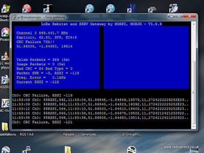
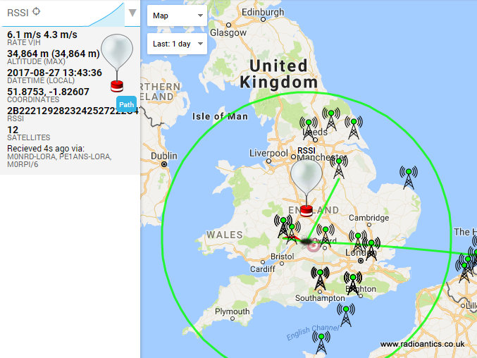
Well it all worked extremely well, and got a lot of decodes as can be seen by the pie-chart generated by the habitat.habhub.org system, the third best receiver only bettered by Dave himself (M0RPI) and a station nearer to the flight path.
 You can see my geographical position relative to the flight below (I am the station NNE with the green line, about 160km away) and received a lot of telemetry strings even when the height of the balloon meant I was outside the 5 degree above the horizon circle (shown in green).

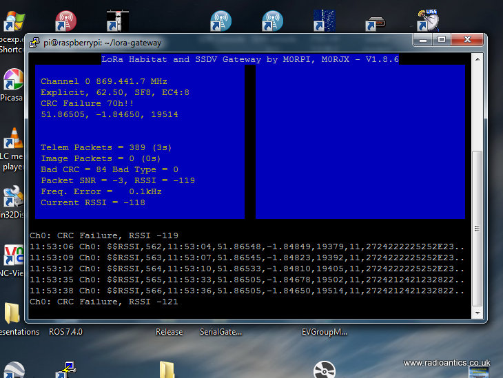
The Pi was connected to my network via WiFi and controlled by a Putty console on my shack PC
It was a useful experiment and I am thinking of installing a dedicated mast mounted LoRa receiver with 868 and 434MHz antennas (and possibly pre-amps and filters) following this result.
868MHz ISM devices are available but are not as widely used. Back in December I posted about trying to track a flight by HAB Enthusiast Dave Akerman who is experimenting using LoRa devices on this band. I had limited success receiving that flight and another ones so when I saw that Dave was planning another flight today using 868MHz LoRa I had a rethink on how to approach tracking it.
The antenna I used was a collinear one built from cheap satellite coax, similar to that I built for ADB-S however rather than having a long coax run to the LoRa gateway I opted to put the Raspberry Pi up on the pole at the base of the antenna to limit any loss.
The antenna can be seen connected to the Raspberry Pi and LoRa add on board, the Pi has a WiFi dongle.

The antenna was inserted into a piece of conduit to keep it upright and it and the Pi were strapped to a 5m painters pole (using a plastic lid as an insulator)

A USB power pack was also strapped to the pole to keep the Pi powered, hopefully you can see it in the photo below.

The pole was put up and was about the same height as my normal dual band collinear

Well it all worked extremely well, and got a lot of decodes as can be seen by the pie-chart generated by the habitat.habhub.org system, the third best receiver only bettered by Dave himself (M0RPI) and a station nearer to the flight path.

The Pi was connected to my network via WiFi and controlled by a Putty console on my shack PC
It was a useful experiment and I am thinking of installing a dedicated mast mounted LoRa receiver with 868 and 434MHz antennas (and possibly pre-amps and filters) following this result.
Shortwave Radiogram
In March 2013 The Voice of America (VOA) started an experiment called the VOA Radiogram which transmitted digital text and images using the powerful 50 year old analog shortwave broadcast transmitter at the Edward R. Murrow Transmitting Station near Greenville, North Carolina.
The idea was anyone could receive the radiogram on any shortwave radio, even an inexpensive portable one with no SSB capability. By feeding the audio from the radio to a computer, either by a audio lead or even using the a microphone the listener could decode the text and images using simple software.
I had seen mention and reports on social media of people receiving them but somehow never got around to trying it myself.
VOA ended the experiment back in June this year a week before the retirement of the program producer Dr. Kim Andrew Elliott. An offer to continue the broadcasts on a contract basis was declined, so a follow-on show called Shortwave Radiogram began transmission from the WRMI Radio Miami International transmitting site in Okeechobee, Florida and Space Line in Bulgaria.
The Shortwave Radiogram transmission schedule is (at the time of writing and all times UTC)
Saturday 1600-1630 9400 kHz
Sunday 0600-0630 7730 kHz
Sunday 2030-2100 11580 kHz
Sunday 2330-2400 11580 kHz
All via WRMI except for 9400 kHz, which is via Space Line in Bulgaria.
I spotted a tweet a few weeks back (can't remember who from) mentioning the @SWRadiogram so my interest was piqued, I wasn't around for this weekends Saturday transmission in Europe but had a go on Sunday for the one from America. I wasn't expecting great things due to the levels of noise and poor conditions of late.
I have the decoding program FLdigi already installed on my computer for other datamodes and for information on how to decode the radiograms (sent using MFSK32) visit this page
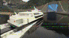
On the 0600UTC transmission I managed just one poor image

but during the Sunday 2030UTC transmission I got four decent images, the fifth was lost to QRM


I also made two short videos (on hand held mobile phone so a bit shaky) which show the incoming text and images.
The idea was anyone could receive the radiogram on any shortwave radio, even an inexpensive portable one with no SSB capability. By feeding the audio from the radio to a computer, either by a audio lead or even using the a microphone the listener could decode the text and images using simple software.
I had seen mention and reports on social media of people receiving them but somehow never got around to trying it myself.
VOA ended the experiment back in June this year a week before the retirement of the program producer Dr. Kim Andrew Elliott. An offer to continue the broadcasts on a contract basis was declined, so a follow-on show called Shortwave Radiogram began transmission from the WRMI Radio Miami International transmitting site in Okeechobee, Florida and Space Line in Bulgaria.
The Shortwave Radiogram transmission schedule is (at the time of writing and all times UTC)
Saturday 1600-1630 9400 kHz
Sunday 0600-0630 7730 kHz
Sunday 2030-2100 11580 kHz
Sunday 2330-2400 11580 kHz
All via WRMI except for 9400 kHz, which is via Space Line in Bulgaria.
I spotted a tweet a few weeks back (can't remember who from) mentioning the @SWRadiogram so my interest was piqued, I wasn't around for this weekends Saturday transmission in Europe but had a go on Sunday for the one from America. I wasn't expecting great things due to the levels of noise and poor conditions of late.
I have the decoding program FLdigi already installed on my computer for other datamodes and for information on how to decode the radiograms (sent using MFSK32) visit this page
On the 0600UTC transmission I managed just one poor image
but during the Sunday 2030UTC transmission I got four decent images, the fifth was lost to QRM
I also made two short videos (on hand held mobile phone so a bit shaky) which show the incoming text and images.
ARISS 20th Anniversary SSTV
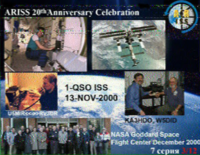
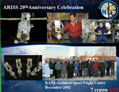
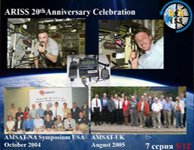
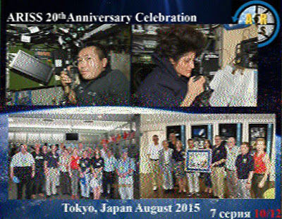
This weekend has seen another SSTV event from the International Space Station, this time in commemoration of the 20th Anniversary of ARISS (Amateur Radio on the International Space Station)
The 20 year history of ARISS was displayed through a collection of 12 images highlighting the accomplishments of the project over the last two decades.
As the ISS has orbited the world it has been transmitting the SSTV signals using FM on the usual downlink of 145.800 MHz, here at my QTH in the UK the passes have occurred late at night into the early morning, averaging 3 - 4 reasonable passes each day.
The signal has been very strong and so some excellent low noise images have been received by many people using just modest equipment. While not the greatest technical achievement in the world it nonetheless generates much needed interest in ARISS and amateur space communication.
My own system consisted of the Yaesu FT-857D and MMSSTV running on the shack PC and was left on automatic receive (I was tucked up in bed) and managed to get decent copies of all the images.
Image 8 reminded me of the fun I had back in 2011-2012 of receiving the ARRISAT-1 and was one of the key things that convinced me to finally get off my backside and actually get licensed, even if it took me another 12 months and to this day haven't really cracked satellites myself! My previous blog posts on that can be found at http://nerdsville.blogspot.co.uk/search/label/arissat-1
Here are the best of my images, for a full description of what each one depicts visit http://ariss-sstv.blogspot.co.uk/2017/07/anniversary-image-descriptions.html


