Posts Tagged ‘repair’
 Repairing a Kenwood TR9500, Part1 – The Diagnosis
From the description of the fault and studying a downloaded service manual I suspected a relatively simple fault and saw an opportunity to acquire it and offered to buy it for the price he had paid. However I have decided to be more charitable rather than mercenary and have offered to give it a look over and repair it for him if I can.
The fault as described was the rig receives okay but on transmit there was a carrier on FM with no audio and a very quiet SSB signal. A faulty microphone had been ruled out and someone had suggested a bad connection internally. Due to the compactness of the unit and the difficulty in dismantling no one had felt confident to attempt any further inspection. I wasn't so sure this was the issue so at the last meeting I picked up the rig and currently have it on the workbench.
TRANSMITTER CIRCUITLooking at the block diagram of the carrier unit and the above functional description in the service manual I suspected the microphone amplifier Q1 to be faulty.
The microphone signal is amplified with the microphone amplifier Q1 (2SC2240(GR)), which is commonly used for both SSB and FM transmission modes and is incorporated in the carrier unit (X50-1720-XX). The amplified signal is then fed to both the SSB and FM circuits.
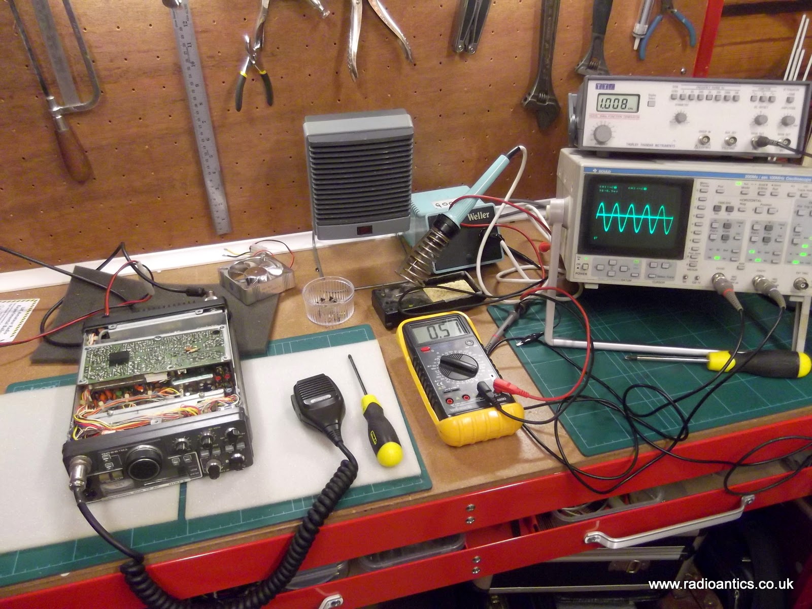
I want to confirm the fault first and so I connected up a dummy load and RF power meter and using the FUNCube Dongle SDR I could observe and monitor the output signal. Sure enough on FM there was a nice carrier at 10W with very faint audio, on SSB there was a small visible signal again with very little modulation. Whistling, blowing and tapping of the microphone could be seen on the waterfall... just!
I connected a switch to the Morse key input and confirmed the rig transmitted in CW with no issue.

On the block diagram there is a switchable tone burst oscillator for repeater access and the output of this is joined to the output from the microphone amp. Encouragingly the tone burst can be clearly seen and heard in the transmission again pointing to an issue with the microphone amp.
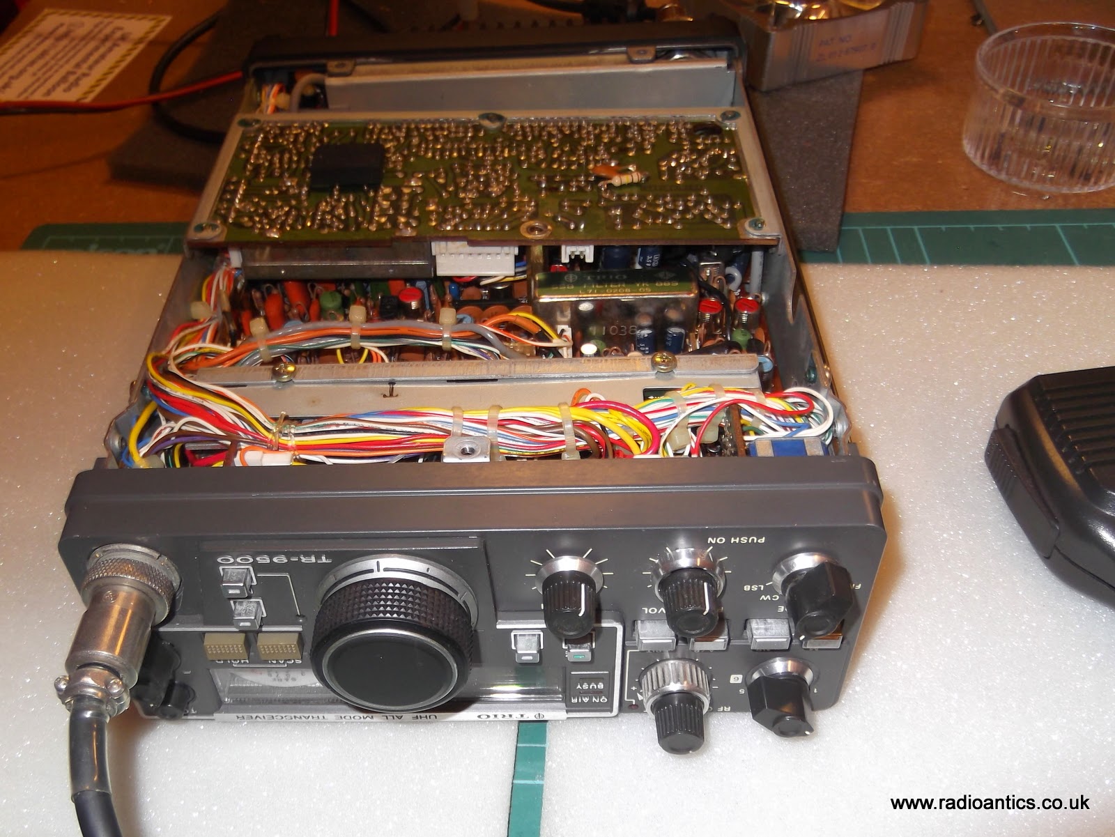
To get to the carrier unit PCB it was a simple matter of removing the bottom cover. The PCB is held in a metal frame mounted with five screws and can be lifted out, as pictured above. But before I did that I checked the continuity to the microphone socket and the 8V supply to the amplifier circuit and both were fine (see diagram below)
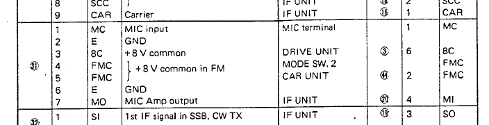

The poor quality image from the scanned service manual shows the bottom of the carrier unit, this is the side of the PCB visible without needing to remove it. The microphone connector is in the top left, putting an oscilloscope on the microphone input (pin1) a signal was observed, however the output (pin8) had an almost identical signal with little or no amplification. Injecting a low level audio signal from the a generator on this pin could be seen and heard in the transmitted signal. This observation together with the tone burst seemed to confirm the other audio circuitry was functioning normally and the microphone amp wasn't.
Actually removing the carrier unit PCB proved a bit tricky as it has a number of small and very secure connectors with ageing and delicate wiring, but I did manage to extricate it and a visual inspection didn't show up any obvious issues such as broken tracks or joints.

This is the detail of the microphone amplifier section from the schematic. Using a meter I have checked the continuity of tracks and have checked all the resistors for shorts or open circuits and they all read the correct values. The capacitors all look okay and checking the signals either side of C3 the C7 coupling capacitors show they are functioning correctly. This left Q1 a 2SC2240(GR) transistor as the likely culprit and I have ordered a replacement which should arrive in the next few days. I am hoping this will make it spring back to life.
Getting off Windows XP
With the impending end-of-life of Windows XP a few weeks ago, I found myself with a bit of a predicament: My shack PC is a dual-core 64-bit system (3.0-GHz Pentium-D) so it’s not really a slouch performer. But, it had only 1 GB of RAM, which was fine for XP. I could upgrade my RAM and upgrade Windows, or I could upgrade the RAM and dispense with Windows altogether.
I opted to drop Windows.
My almost-3-year-old son helped me install 4 GB of RAM last weekend. (Actually, he spent more time asking about the capacitors on the motherboard. Kids these days.)
I’m a long-time GNU/Linux user (just over 15 years, actually) and fan. However, as I wrote once in the past, I’m also fan of getting things done. So, I kept using Windows 95 / MS-DOS for many years on my hamshack computer, with a brief several-year foray into using Windows XP when I moved to TR4W logging software. Linux finally became ready for prime time in my hamshack when Kevin, W9CF, ported TR-Log over a couple of years ago. After ensuring it wasn’t a fad, I was ready to jump. Over the past week or so, I’ve been tailoring the setup of everything to bring back the functionality I had previously.
So, what broke?
- I have an nVidia graphics card for my second monitor. Failure. Not sure how much I care. Maybe I’ll look for an old ATI card or something else with drivers? Anybody have a plain PCI video card with VGA or HDMI kicking around?
- Windows-specific software that I’ll probably just quit using: AVR Studio and SH5. Didn’t really use these much anyway.
- Now, for the truly bizarre: My Elecraft K2/100 throws an ERR 080 on power-up if I disrupt communication between it and TR-Linux (does not matter if the K2 goes off first or TRLinux quits first). I have to disconnect the RS-232 cable at the back of the K2 for a while and then it comes back OK.
- ARRL’s Trusted QSL software version 2.0.1 didn’t compile immediately without dependency problems. Further study indicated.
And, what works?
- TRLinux talks to both the K3/100 and the K2/100, as well as the YCCC SO2R+ controller.
- Made some QSOs and uploaded the signed log to LoTW.
- Pretty much everything else…
W3APL/B 903-MHz beacon
Late last Summer, it came to my attention that the 903-MHz W3APL beacon had gone off-line. The failure was intermittent and seemed to resolve itself after power was reset. Several efforts to troubleshoot it were undertaken by myself and others, including running it at high duty into a dummy load over a period of days. I was unable to get the problem to manifest itself on my bench.
A synthesized source (Analog Devices demo board) was offered by a friend of the Club, however it did not produce the desired output (or any output at all). It’s not clear whether this was the fault of the synthesizer or the user (me). The notional plan was to replace the beacon, which consists of a 75-MHz crystal oscillator followed by 12x of multiplication and a small RF power module, with the synthesizer and a new RF power module. The project languished, as they often do in my hands. But, two weeks ago I picked up the task again and made some real headway.
Really, the failure had to be one of a couple of things: 1. Intermittent connection exacerbated by thermal cycling. 2. Oscillator “unlock” due to component aging and thermal cycling. I reasoned that as long as we could eliminate #1, the multiplier chain and amplifier should be fine. The behavior seemed to point toward #2 or perhaps a combination of #1 and #2. I came across a forlorn Programmed Test Sources PTS-040 that I had rescued from another group’s surplus heap to put in my lab. I hadn’t used it in the two years that it was in my possession, so it seemed logical to provide it to the Club on a long-term loan. The problem was that it didn’t go up to 75-MHz. So, I cooked up a little multiplier chain. My “good” HP spectrum analyzer is on-loan to a paying program so I had to make do with the FFT function on the fastest Tektronix portable scope I had in the lab.
My initial effort at the multiplier chain was to build a 2N3904 amplifier that swung way into saturation producing a signal rich in harmonics. I went straight away for the 903-MHz signal but I couldn’t get a good enough lumped-element filter to eliminate the adjacent harmonics. So, I tried for the 75-MHz injection. This demanded a buffer amplifier so I lazily reached for the MMIC drawer in and retrieved one of the plentiful MAR-8s. Plenty of gain…and, as I would find out in a moment…conditionally stable! To exercise the eloquent euphemism of Ben, N3UM, the MMIC “burst into song” at about 63 MHz.
Back to the drawing board. I knew that I had something that would work, so I redesigned the deadbug layout on an SMD protoboard (the kind with all the pads in a grid). I replaced the discrete 2N3904 and MAR-8 MMIC amps with SGA-4586Z MMICs (which are a little too nice for this service, but I have a ton of them). Viola!
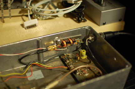
It’s the little board on the far wall of the diecast box with the SMA connector on the left and two toroids. 37-MHz RF comes in from the PTS-040 through the BNC jack in the wall. It’s multiplied up to 75 MHz on the new board and piped down to the remaining 12x multiplication and amplification stages before going to the little brick PA in the lower left (not visible).
So far, it sounds good. I was able to monitor it with my W1GHZ transverter strapped to the IC-290A in my car and using a WA5VJB cheap Yagi tossed in the back seat. I lost the signal about 5 miles away with that setup, which is really pretty decent all things considered at that frequency, etc, etc. Nominally, the frequency should be 903.054 MHz. I found it at about 903.048 MHz on the lash-up. Brian, ND3F (aka N3IQ/R) reported that he found it at 903.046 MHz with KA3EJJ’s setup. If you’re in the vicinity of FM19ne and are setup on 902/903, we’d appreciate a report. The big thing is the long-term stability. So, we’ll continue to monitor it.
Now…to get back to that 930 on my bench…
The Johnson 275W Matchbox Antenna Tuner
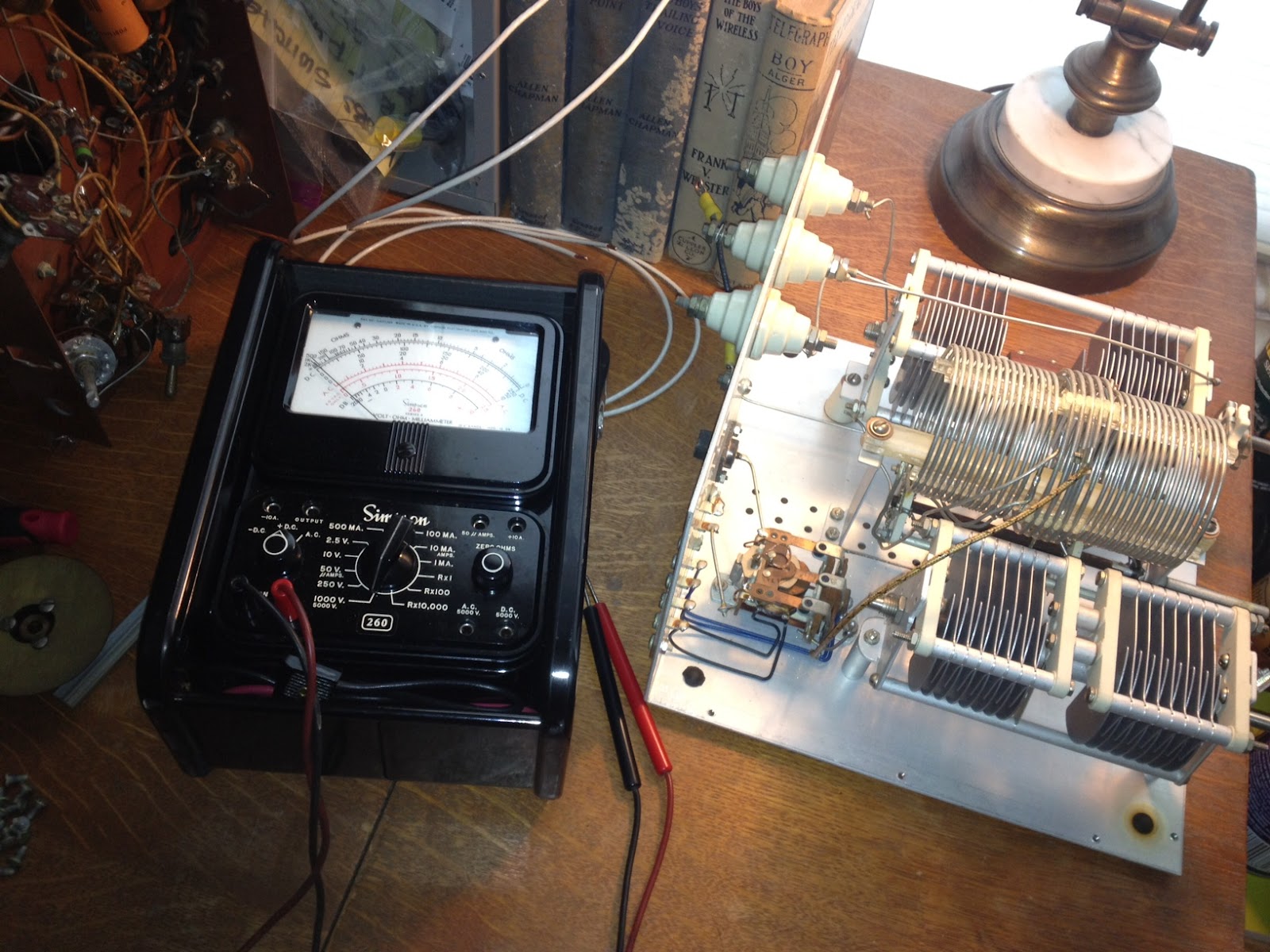
I had purchased a Johnson Matchbox from an estate a while back & decided that while I was home with the flu I would open it up and check on its condition.
 The Johnson Matchbox is found most commonly in two versions, the smaller “275W” unit and the larger Kilowatt Matchbox. Why did I use quotation marks around 275W? Well, these units were manufactured back in the good old days when men were men and transmitting voice meant using AM, not single side band. The conservative rating of 275W of AM translates into roughly 800W of peak SSB (Not really but close enough so you get the idea)
Unlike many who own a Matchbox I was hoping to keep it 100% original and that it would contain all its original components, including the antenna change-over relay and wiring for the high-impedance receiver antenna connections. I plan to use this Johnson Matchbox with a Heathkit AT-1 transmitter and Hallicrafters SX-25 receiver so the inclusion of an antenna change over relay and 300 Ohm receiver connections will make life MUCH easier. Something I didn’t realize until I had the unit apart (There are a LOT of screws holding this thing together) is that there is also a receiver control contact on the relay to break HT and mute the receiver during transmit which will work with my SX-25.
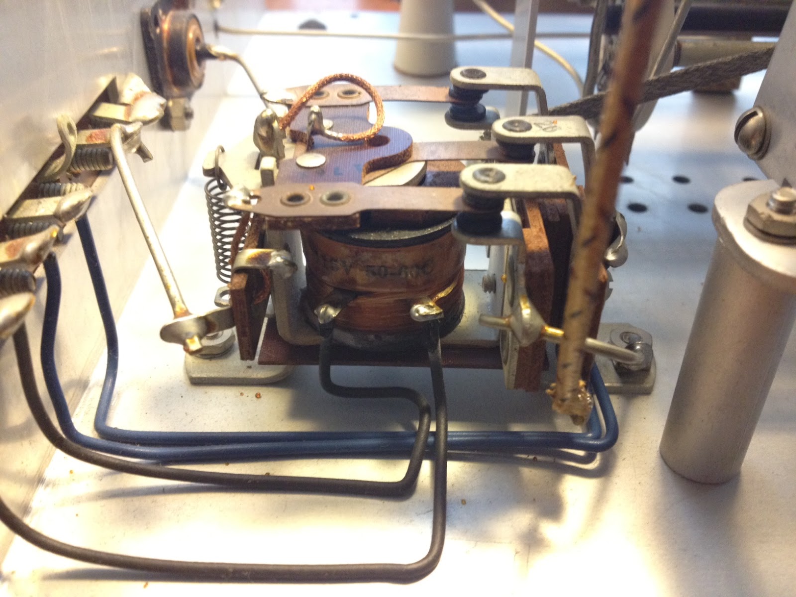 An initial inspection showed that the only modification was a small piece of plastic wedged into the relay contacts that held the relay in the transmit position. It was easily removed and the relay coil and contacts tested for continuity. The contacts seem a bit dirty which, from the little I have read online, seems to be a common problem.
Once the relay contacts and band-switch are cleaned I will button the unit back up and connect it to the loop antenna I have recently run around the eaves of the house. The loop has been a huge improvement to the long-wire and magnetic antennas I have run in the past, at least as far as reception goes … but that is a topic for another post.
Something old, something new.
Something old …
As a young boy in Australia my two favorite hangouts were my grandfather’s shed or practically anywhere that electronics were sold. The two largest electronic component retailers in my home town were Tandy (Radio Shack) and Dick Smith Electronics. They both sold kits, tools, ‘100 in 1 Labs’ and other assorted gear but Dick Smith eventually became known as the experimenters store due to their greater range.
 |
| Original Radio Shack calculator |
If you would like to make one of these yourself then Adafruit Industries has created a PDF document you can print and cut out for create your own resistor value calculator.
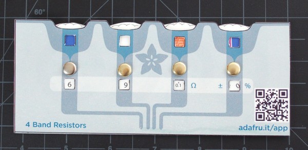 The PDF file is available from Adafruit Industries or a copy is also here. Once you print it out, a little cutting and folding should produce something like the example of the right. The Adafruit design uses brass paper fasteners (remember those?) but any fastener could be used that would allow the wheel inside to rotate freely. It would be best to print on heavy card stock if you have the ability as it will give the calculator some strength.
Something new …
If you happen to have one of those new fangled iDevices you can download Circuit Playground. It has a few more features than the old Radio Shack calculator and looks great on the iPad.
More features are being added but the list at the moment includes:
- Decipher resistor & capacitor codes with ease
- Calculate power, resistance, current, and voltage with the Ohm’s Law & Power Calc modules
- Quickly convert between decimal, hexadecimal, binary or even ASCII characters
- Calculate values for multiple resistors or capacitors in series & parallel configurations
- Store, search, and view PDF datasheets
- Access exclusive sneak peaks, deals & discounts at Adafruit Industries
You can download it from the iTunes Store or, if you have an Android, you can check out ElectroDroid for similar functionality.
As time goes on there are more and more useful utilities available for electronic experimenters on iOS and Android devices. Since more and more equipment today is becoming computerized do iOS and Android devices represent the future of test equipment?
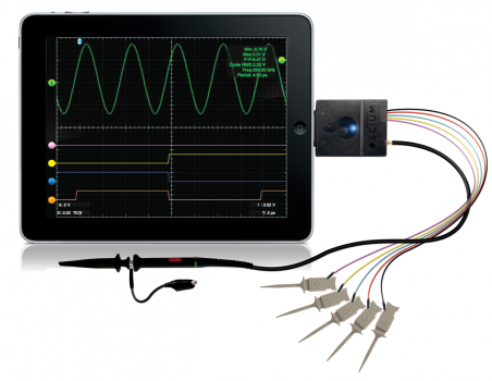 |
| iMSO-104 iPad Oscilloscope |
(No?) Nonsense Radio
The November 2011 issue of QST contains an Op-Ed that really left me shaking my head more than normal. The author bemoans the complexity and feature sets of newer handheld radios and pines for the days of his IC-02AT. He goes on at length about the “unnecessary” receive capabilities (NOAA weather broadcasts, AM/FM radio, etc) and how he has to search for the manual every time he wants to program a repeater offset.
Well, as someone who recently upgraded from a radio just slightly newer than the IC-02AT to a “modern” HT, he’s wrong on nearly every account (except the micro-/mini-USB port, which I would wholeheartedly support for charging purposes).
- Eliminate extraneous features. Too bad we all have different definitions of this. I think scanning is a worthless feature, but like NOAA/NWS weather broadcasts. In fact, my wife is delighted that we now have a battery-powered AM/FM+NOAA/NWS radio again that I will always be able to find and will guarantee that it works. Did you hear that, guys? My non-ham wife actually likes my HT and uses it to listen to FM radio!
- Eliminate multilevel menu trees. I’m just dying to replace my cell-phone-sized VX-3r with a knob-covered brick. I’m sure you are too. It’ll look great in my shirt pocket.
- Eliminate the proprietary programming cables. Maybe I’m not a typical ham, but I only have about ten memory channels programmed into my VHF/UHF FM radios and they took about 10 minutes to program through the front panel (my bad, menus). The mini-/micro-USB port is a good idea for charging, though.
- Allow for a battery pack that uses disposable batteries. Last time I checked, most radios have this option. Did I miss something?
- Create an inter-vendor standard for user interface. What if they standardize on Icom?!?! The last Icom VHF/UHF FM radio I used received a “grade of S, for ‘stupid’” from its owner. That was in 1993. All of the Japanese manufacturers will be put out of business by the factory owned by the Chinese military that produces their products before this happens.
He should buy another IC-02AT if he liked them so much. I bet for a Jackson or two, you could have a nice one…complete with the 6x AA battery holder. Heck, buy two or three for spare parts. I think I have the Service Manual around here somewhere if I didn’t already sell it.
On a more serious note, there are lots of no-frills radios available out there, even brand new ones with factory warranties. Until recently, at least, the money in VHF FM radios was in two-way, government, and public safety, not amateur. There are a lot of amateur rigs at the “low end” of the market that share a lot in common with their commercial counterparts. And, of course, you can always buy used Motorola gear on eBay if you desire ultimate performance and ruggedness.
Amateur Wiring

I’ve picked up a couple of Mirage “brick” amplifiers over the past few years. I’ve also rewired the DC cable on each and every one. Here’s the latest. AWG 10 to AWG 16 transition? Seriously? I know it technically doesn’t matter too much for a short run, but these amplifiers suck down a lot of current and I just don’t see cutting corners on that. Maybe I’m a purist…


