Posts Tagged ‘Projects’
 Winter project line ups
Now that fall is in full swing and most.....typo alert remove "and most" (thanks to Gary at rework eliminator for Elecraft K2)and soon all the leaves will have dropped from the trees. The temps already are starting to drop not yet to freezing but soon. So outdoor activities will be more limited as winter gets her firm grip on this QTH.
I find that radio conditions do improve in the winter months and there are some major CW contest to keep me busy on some of the weekends....but.....I don't know about my readers but I also like to have a few winter radio projects on the go. This winter's project is an ambitious one that satisfies my kit building hunger. I purchased another Eelecraft K2 kit, my first K2 kit was a blast to build. With this kit I want to take my time and very much enjoy the build. Another decision I made was to sell the rig once built and run through it's paces. I then can use those funds to put toward my next winters project. I try to keep what I call my well rounded approach to ham radio. This includes on air operating time for sure, reading my monthly ham radio
magazines, blogging and blog reading, interfacing computers with the hobby and of coarse kit building. I also wanted to add a CW tuning aid to my original Elecraft K2 and it just so happens that K6XX has a kit to add a CW tuning indicator to the rig. This kit has the dreaded SMD parts!!!! Now having said that I used to say that about kits that came with winding toroid's and that is not a big deal anymore. Below is a video of how the tuning light works.
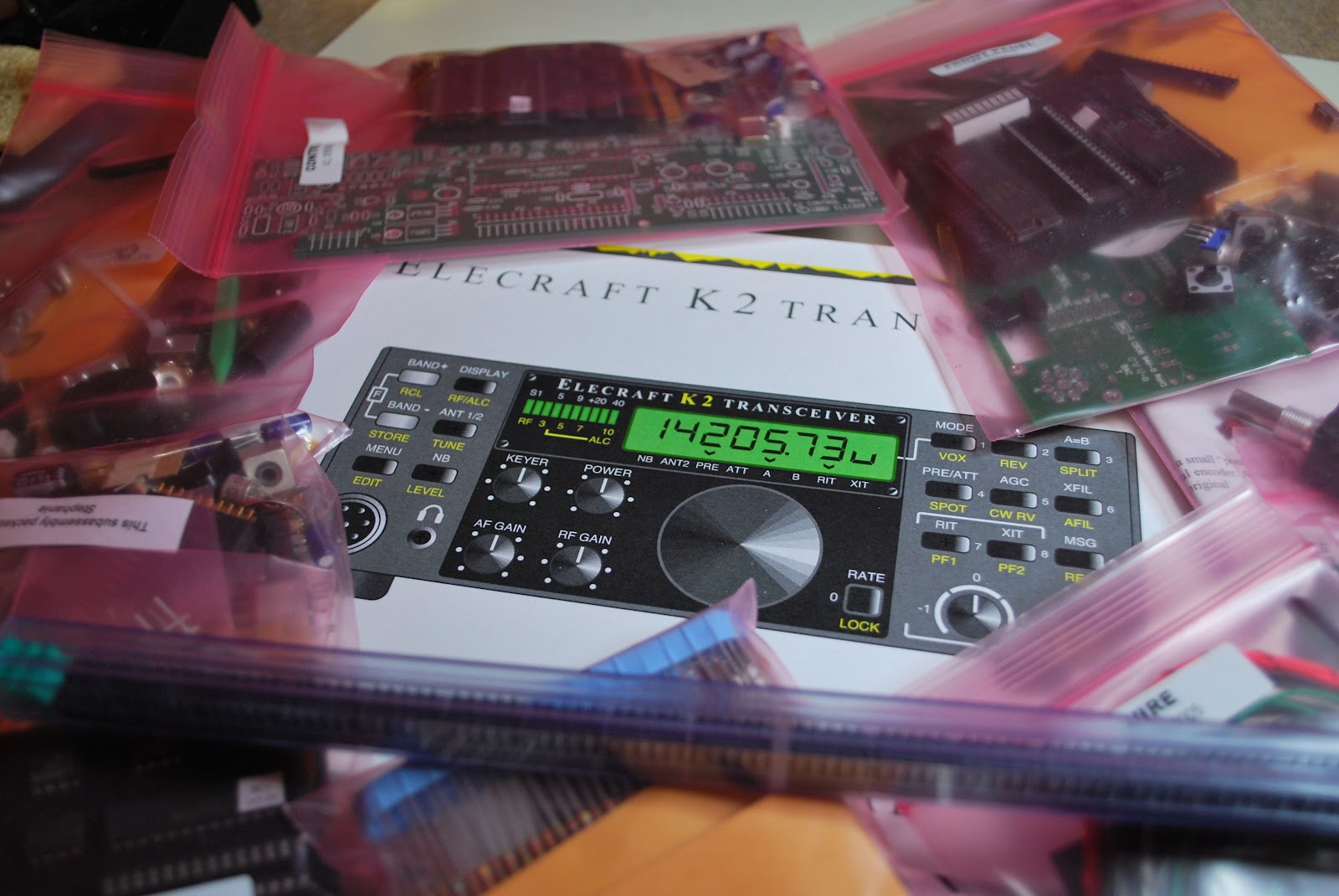 |
| Serial 7372 soon in the works |
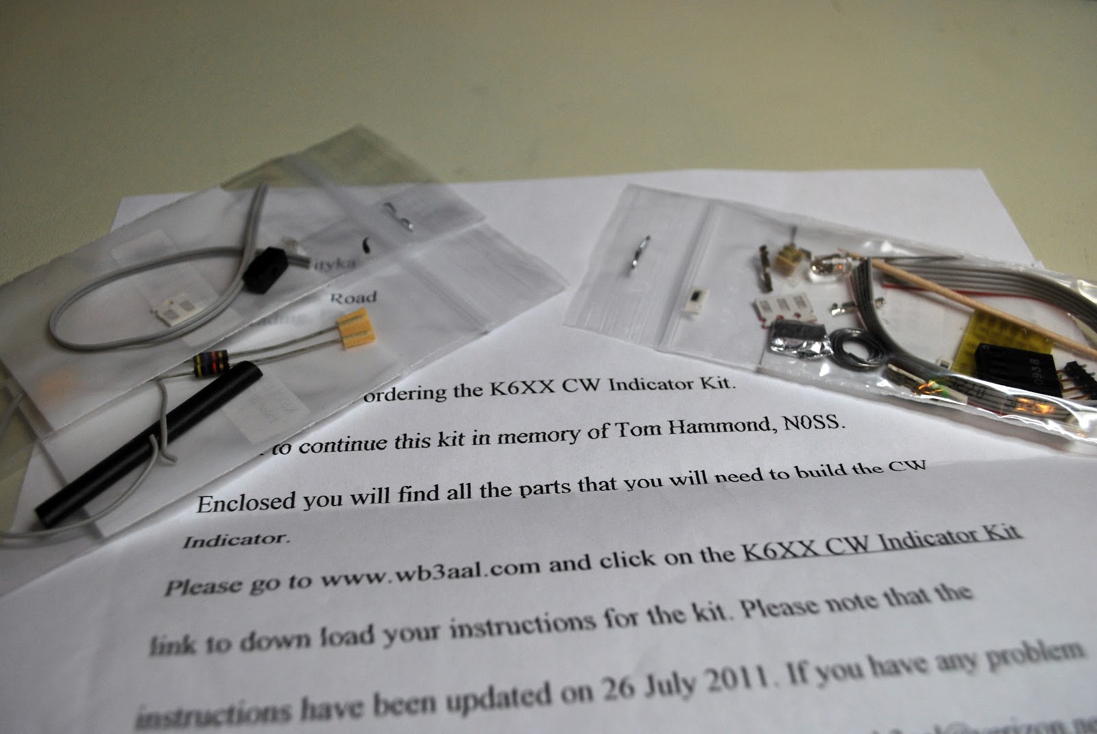 |
| K6XX's kit for the K2 |
Fourth and final KX3 video………
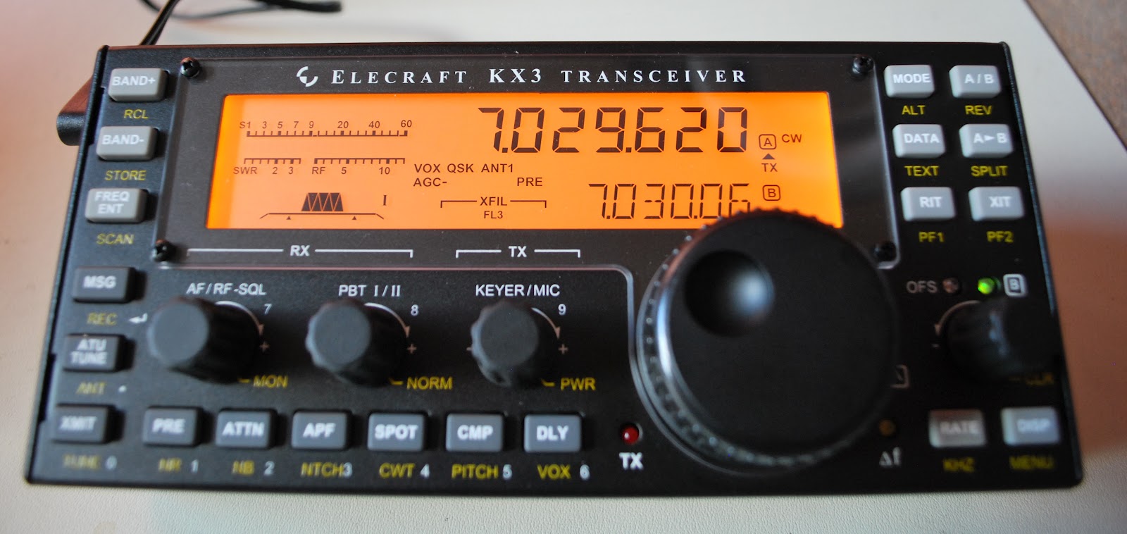 |
| Up and running |
Elecraft KX3 part 3 youtube assembly video
Well the KX3 is almost completed and this is the 3rd of a 4 part assembly video of the radio. In this YouTube video I go over the problems I had with the ATU installation, the roofing filter board issue and the battery holder oops I had and needed to correct before there was damage. The build is almost complete but have a look and either get excited about purchasing one or pick up some pointers before you do your build.
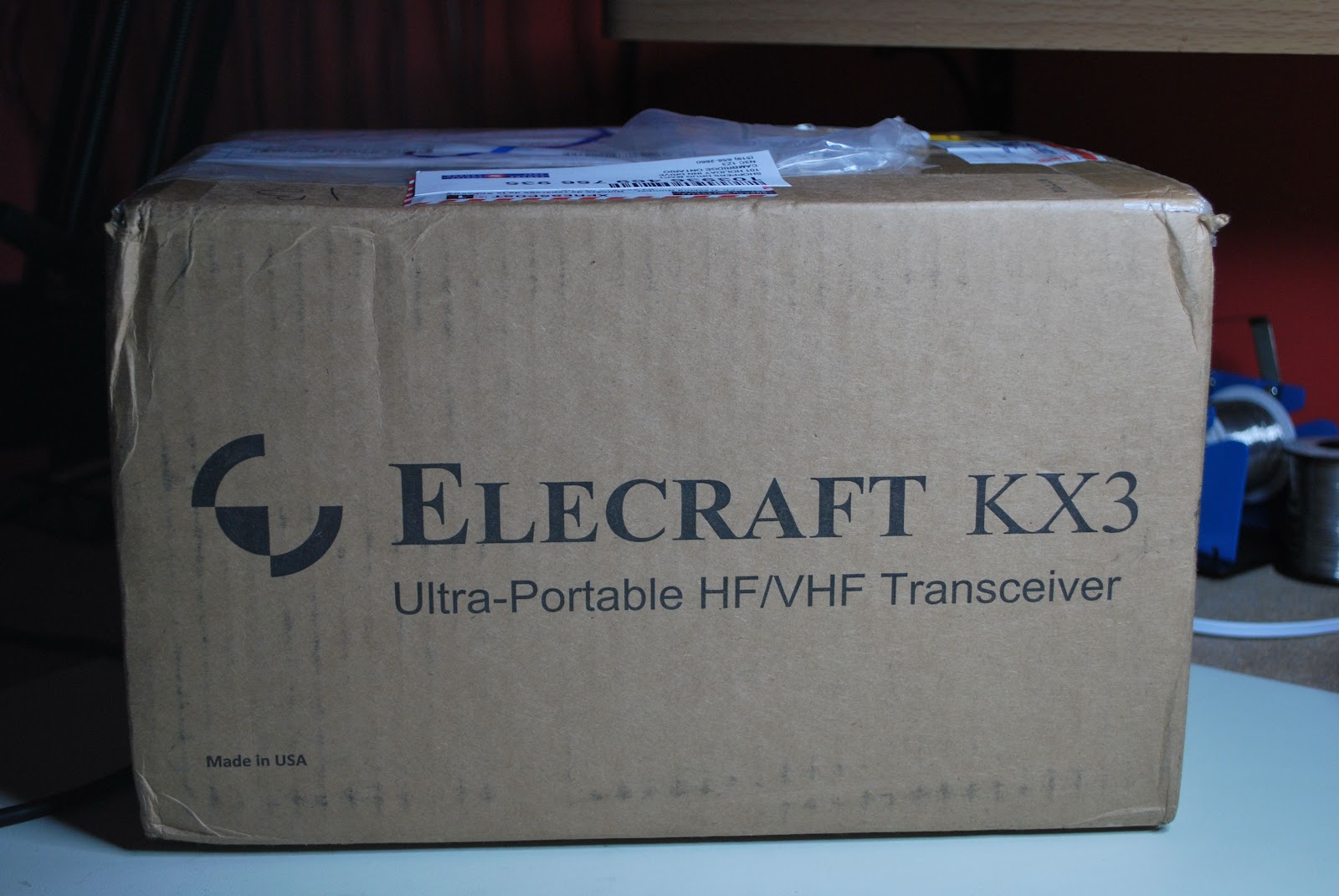
My KX3 assembly video part one
This is my first time using Imovie with my Mac computer to edit a video. There are many great things that can be done using this program, things that over time I am going to have to learn. This is part ONE of a four part series. I am working on the editing of part two now and hope to add more flavor the the movie. Part ONE is a little long but now I have the hang of how to edit and shorten them.
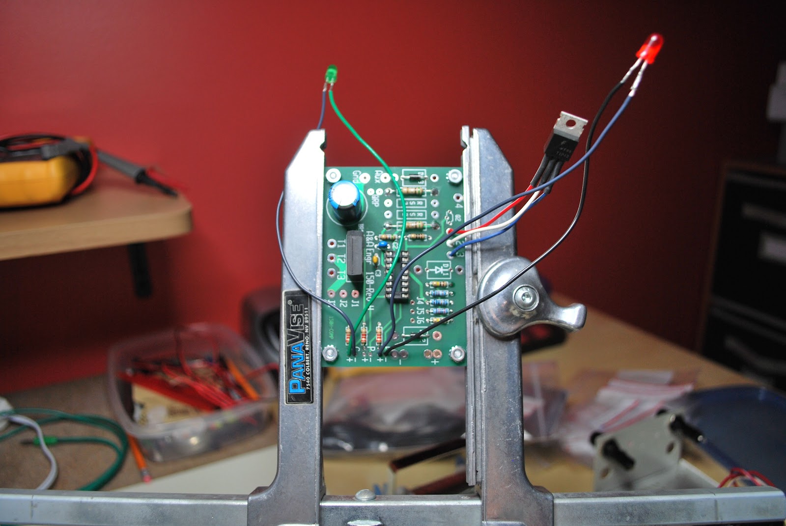
A VERY SMART charger
 |
| Charger ready for testing |
1. The charger can be connected to the battery indefinitely and no harm will come to the battery. Once the battery is fully charged the Smart charger will remain in maintenance mode delivering a float charge. Therefore the battery cannot be over charged.
2. The charger can stay hooked up to the battery while operating the radio if you so choose to do so. The charger will enter the bulk mode to help with the load of the radio operating.
3. When the charger is connected it automatically determines the type of charge the battery needs.
 |
| Close to done but no heat shrink on LED |
 |
| Top view with no jumpers or D1 ops |
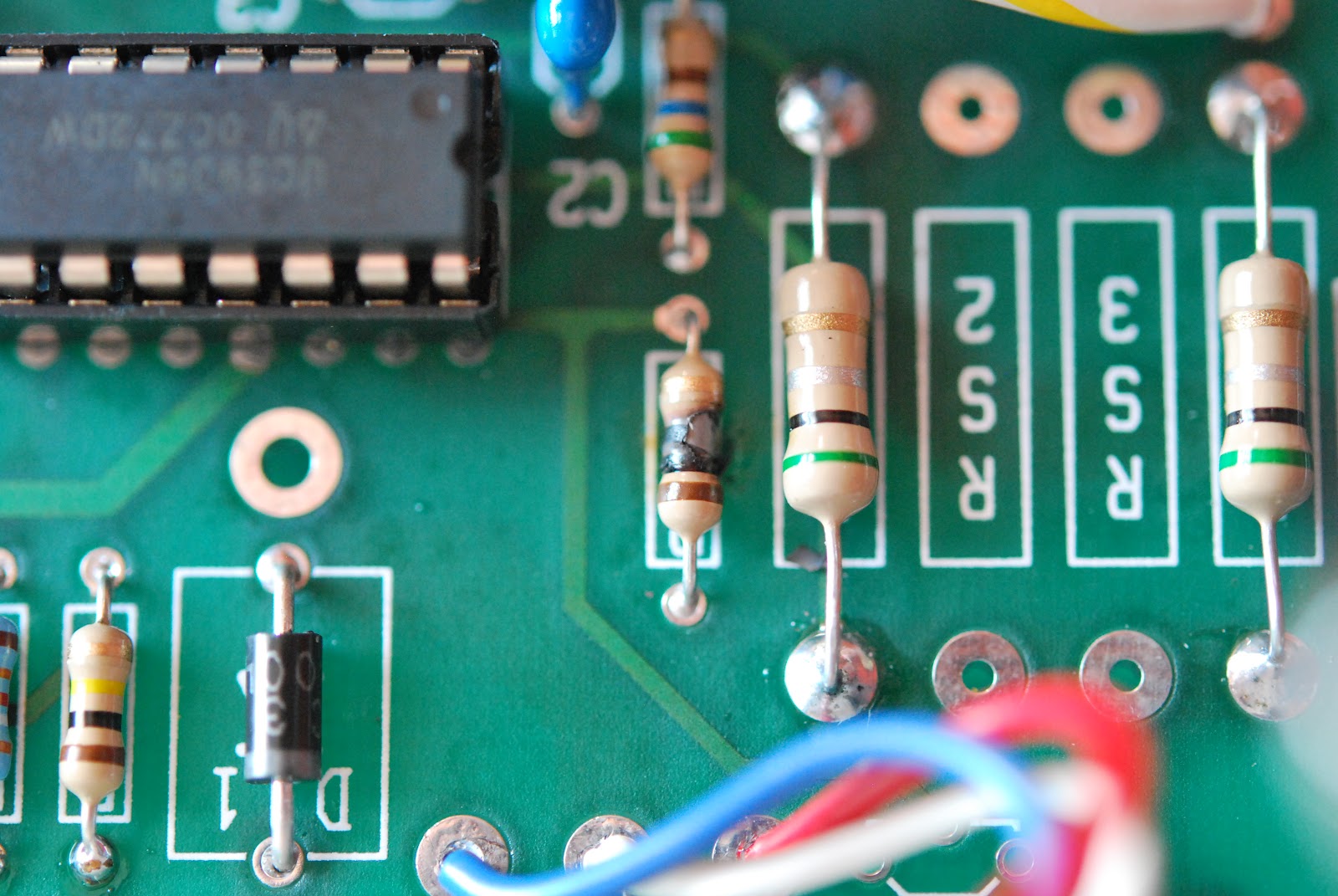 |
| Fried resistor |
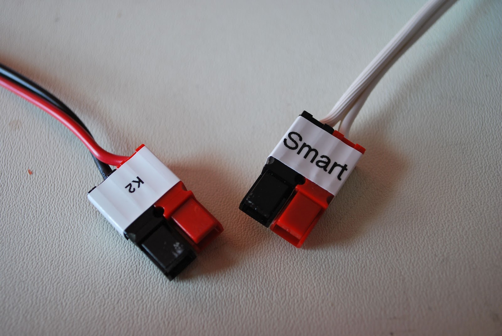 |
| Decided to use Anderson conn's |
either:
1. You are in measuring in the wrong place.
2. You have made a mistake in the assembly.
In either case nothing has been toasted
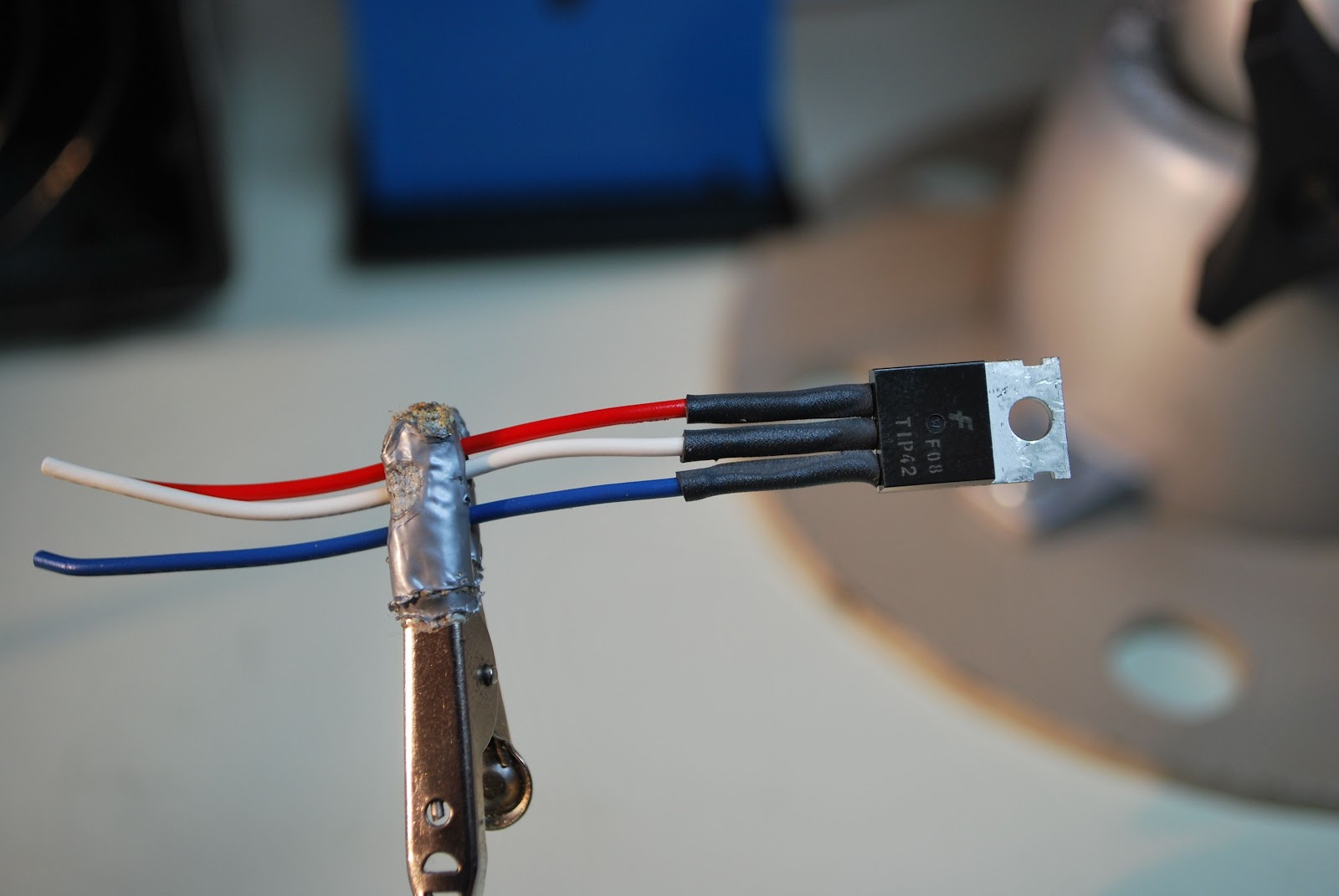 |
| Some heat shrink fun |
1. The heat shrink tubing is very clearly stated to go on the transistor but it also should go on the leads of the LED's...that was not so clear and I have redo the LED's.
2. Make sure you add the jumper J1 to J2 in my case it is mentioned but off to the side of the instructions
3. There is no diode to be installed in D3 position, instructions just say install parts and there are is D1, D2 and D3. Just install the diodes (both are the same diode) one in D1 the other D2.
 |
| D1 needs to have the diode not D3 |
4. If you ordered the QRP version of the charger as I did you will get a separate kit that allows the charger to switch between two charging currents. Read those instructions and install the resistors they tell you too or you will end up removing resistors if you follow the main instructions then move to the add on kit instructions as I did.
5. When done remember the output leads will SHOW NO VOLTAGE UNLESS A LOAD IS APPLIED.
6. The document required to test the unit can be found at the link above under "test procedure". BUT when you do it be very careful!!!
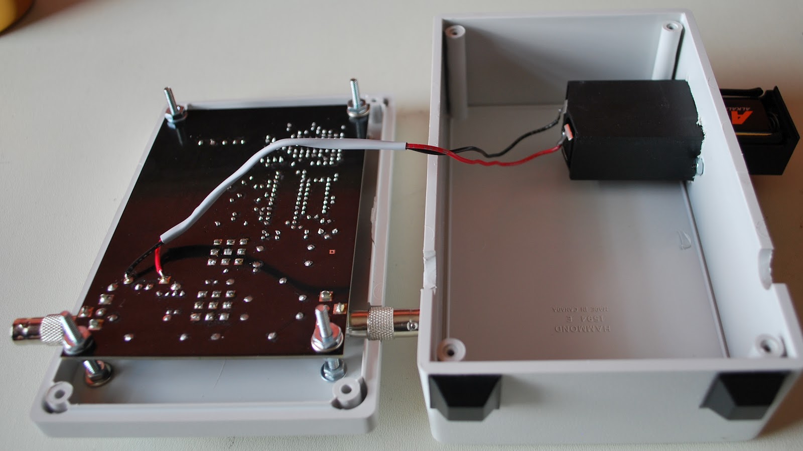
QRPometer case….
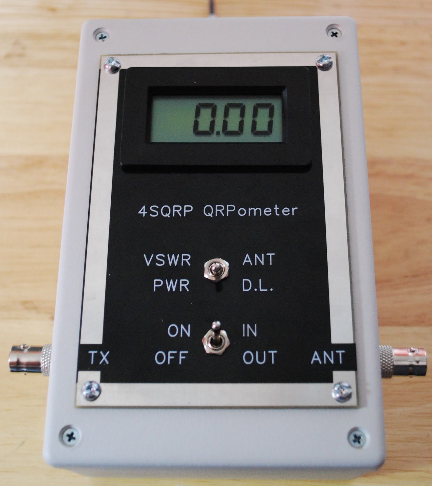 |
| Finished product |
A few months ago I built and blogged about my QRPometer build from the 4 state qrp club its a great kit. In the post there was only 2 con's that I could think of regarding the kit.
1.The TX and Antenna connections were RCA and not BNC, the kit now ships with the RCA to BNC adapters.
2. The meter did not come with a case and the rear of the meter had an exposed circuit board. I felt this left the meter vulnerable to damage.
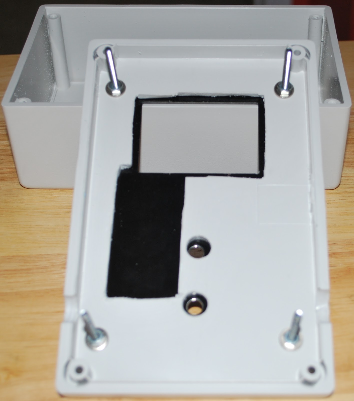
My solution to problem number 2
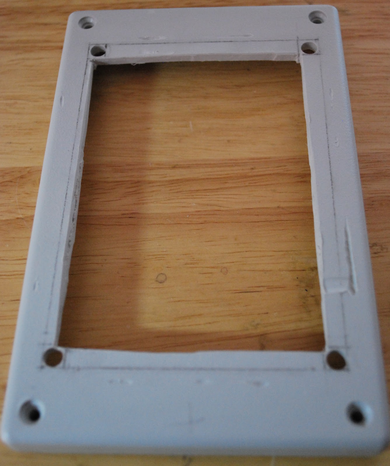 |
| first attempt....not good |
 |
| New opening and front plate on |
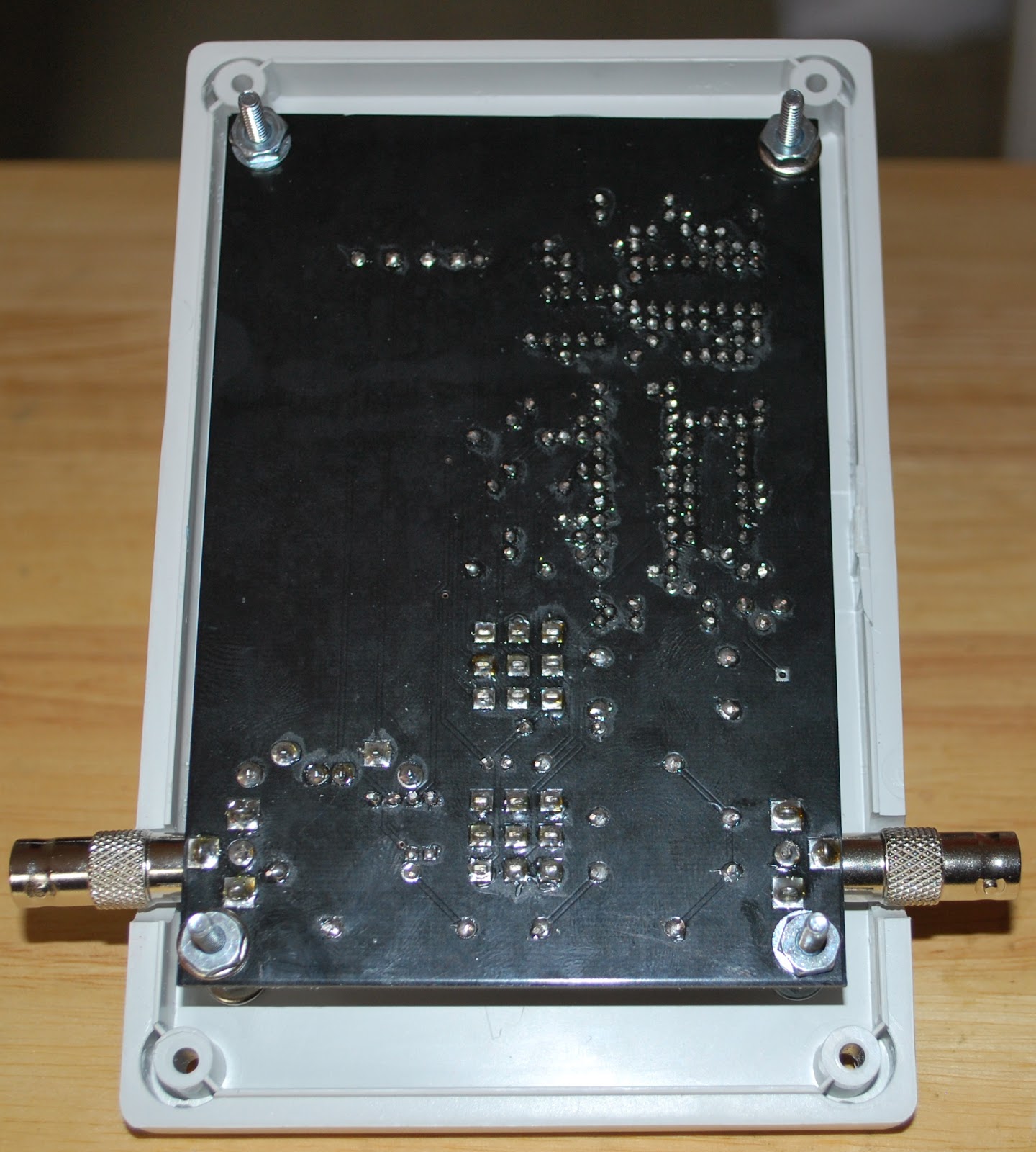 |
| Meter in the new case |
 |
| 9 volt battery mod |
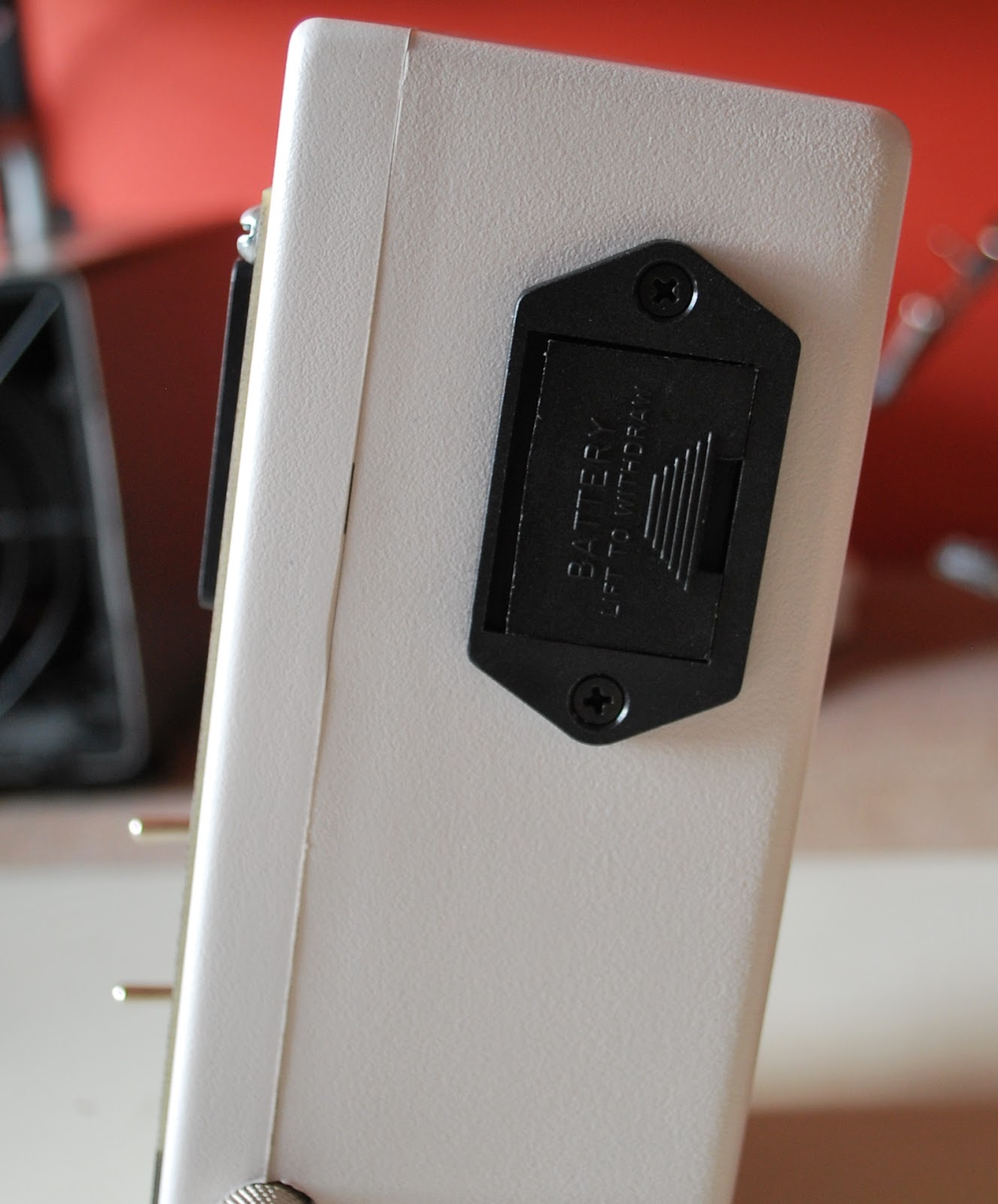 |
| Side view of 9v holder |


