 |
 A VERY SMART charger
 |
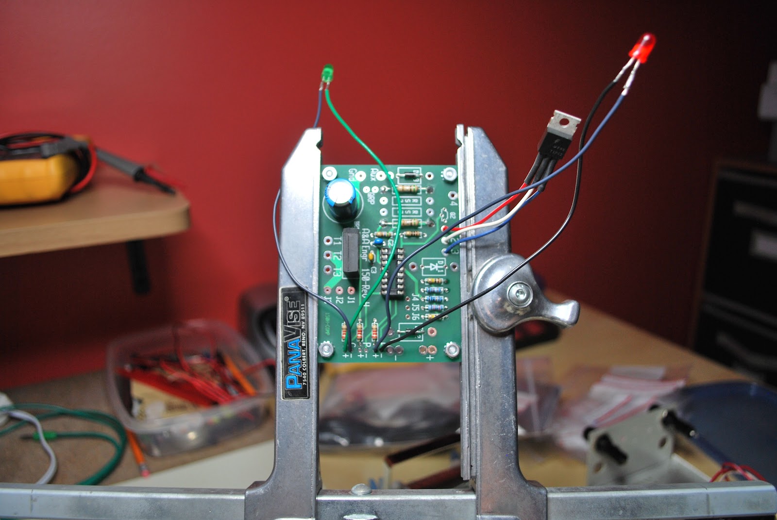
| Charger ready for testing |
1. The charger can be connected to the battery indefinitely and no harm will come to the battery. Once the battery is fully charged the Smart charger will remain in maintenance mode delivering a float charge. Therefore the battery cannot be over charged.
2. The charger can stay hooked up to the battery while operating the radio if you so choose to do so. The charger will enter the bulk mode to help with the load of the radio operating.
3. When the charger is connected it automatically determines the type of charge the battery needs.
 |
| Close to done but no heat shrink on LED |
 |
| Top view with no jumpers or D1 ops |
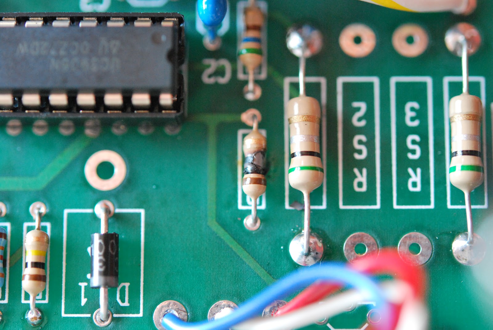 |
| Fried resistor |
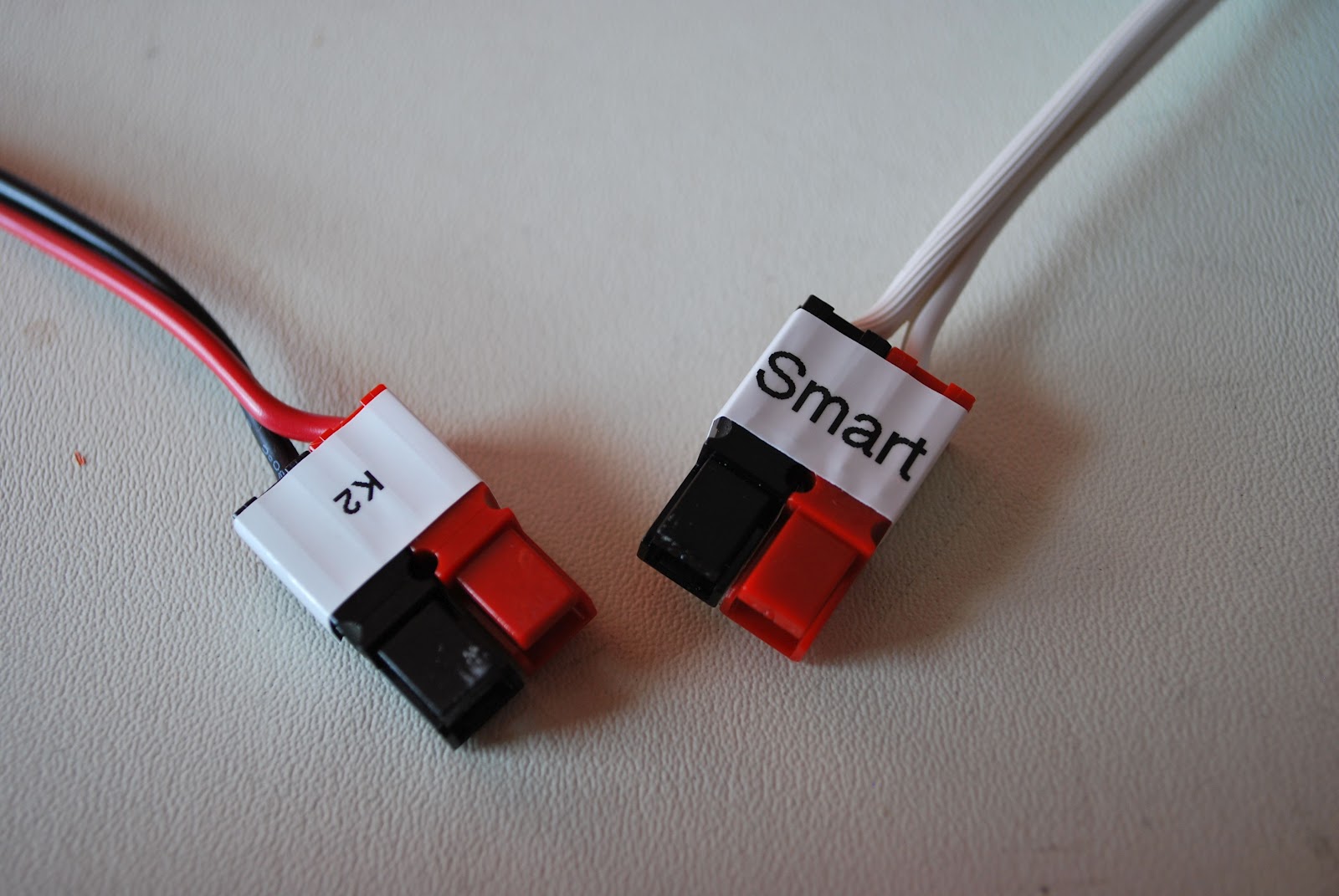 |
| Decided to use Anderson conn's |
either:
1. You are in measuring in the wrong place.
2. You have made a mistake in the assembly.
In either case nothing has been toasted
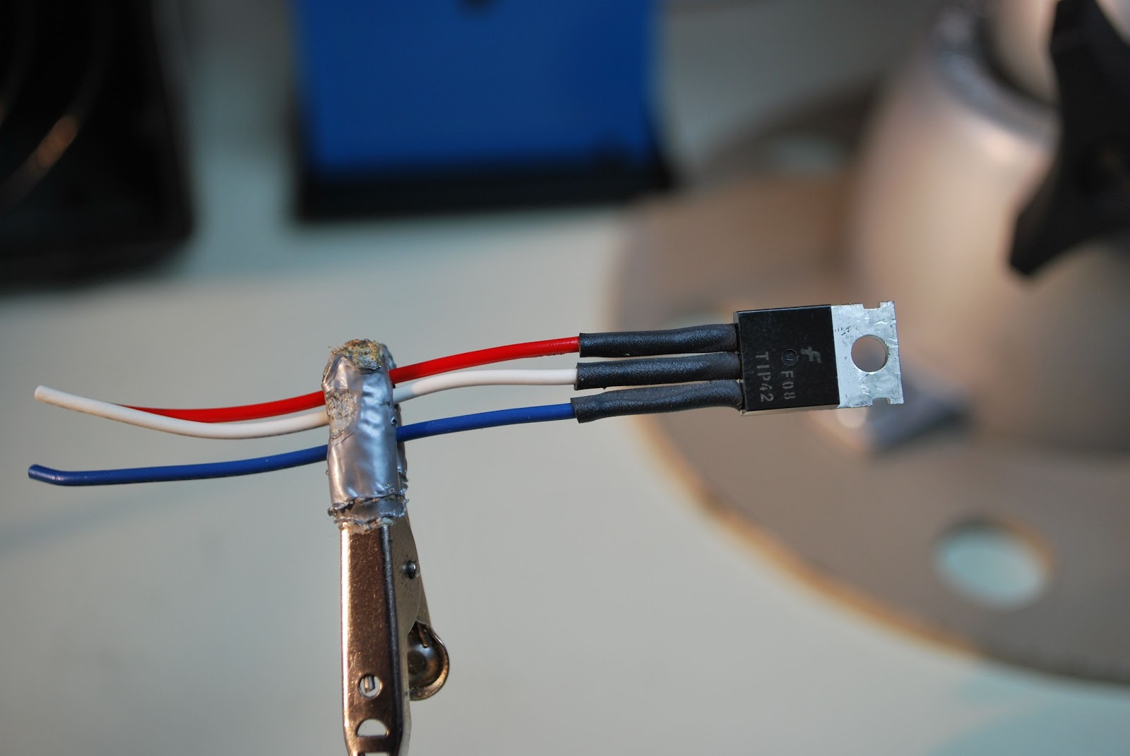 |
| Some heat shrink fun |
1. The heat shrink tubing is very clearly stated to go on the transistor but it also should go on the leads of the LED's...that was not so clear and I have redo the LED's.
2. Make sure you add the jumper J1 to J2 in my case it is mentioned but off to the side of the instructions
3. There is no diode to be installed in D3 position, instructions just say install parts and there are is D1, D2 and D3. Just install the diodes (both are the same diode) one in D1 the other D2.
 |
| D1 needs to have the diode not D3 |
4. If you ordered the QRP version of the charger as I did you will get a separate kit that allows the charger to switch between two charging currents. Read those instructions and install the resistors they tell you too or you will end up removing resistors if you follow the main instructions then move to the add on kit instructions as I did.
5. When done remember the output leads will SHOW NO VOLTAGE UNLESS A LOAD IS APPLIED.
6. The document required to test the unit can be found at the link above under "test procedure". BUT when you do it be very careful!!!
4 Responses to “A VERY SMART charger”
Please support our generous sponsors who make AmateurRadio.com possible:
 Ham Radio Deluxe |
 W5SWL Electronics |
 Ham Radio Prep |
 KB3IFH QSL Cards  Hip Ham Shirts  HamRadioAuctions HamRadioAuctions Reliance Antennas Reliance Antennas Enigma Shop Enigma Shop |  morseDX  Ni4L Antennas  R&L Electronics R&L Electronics antennas.us antennas.us QRV QRV |
- Matt W1MST, Managing Editor

Cool! That is a smart charger!
http://youtube.com/user/kk4ddx
Good afternoon Caleb, yes its amazing what the charger is able to do…what I like about it is hook it up and forget about it until I want to use the K2 again.
For those that don’t want to have to figure out which of the dozen or so “A&A Engineering” companies that come up on Google’s first page of results is the one that makes this charger, it’s:
http://www.a-aengineering.com/
Marty that’s a great idea thanks for posting the link. Should have come with that one when I did the post. I apologize to all those I sent on a Google wild goose chase.
Mike
VE3WDM