Posts Tagged ‘Projects’
 Homebrew Buddistick Project – Part 2
I earlier posted about building a home-brew Buddistick antenna from the instructions posted by Budd Drummond. I posted the link to his site and instructions in the previous post. Look in the sidebar to the right for a quick way to the last post.
I delayed working on the antenna as I did not have a power supply for my radio so I was in no hurry. Well the power supply showed up this last Friday so Saturday morning, I was determined to finish the antenna and get on the air. The first this I did was finish wrapping the coils and crimp the Radio Shack connectors to the ends of the wires.

Next came long nut coupler which the antenna whip will screw into. A bolt is screwed into the nut coupler and the inserted into a small piece of PVC pipe. The nut coupler was a bit small so I made up the difference with a few wraps of electrical tape as Budd suggested in his instructions.

Next came the short piece of wire with a clip and ring terminal on each end. This is used to connect the top of a coil with the base of the antenna.

I bought a nice piece of RG-8X coax that had PL-259’s on each end. The instructions call for dividing the coax into the shield and center section and attach a Radio Shack clip to each of those. Well I spent a fair amount of money on this cable and did not really want to cut one of the connectors off the cable. I thought it would be nice to have some sort of adapter so I could use different lengths of cable over time if needed. This would allow me to have standard sections of cable with PL-259 connectors on the ends and be more versatile in the long run without having a cable dedicated to this antenna. To solve that problem, I came up with this little thing.

It is simply a chassis mount for a PL-259. I soldered two small wires to the center and outer portion of the mount and then added the blue clips. The center wire goes to the bottom of the vertical portion of the antenna, and the wire coming off the outer part of the chassis mount goes to the radial wire. I used different male/female connectors to avoid being able to connect it wrong so if I start making connections at the top near the whip and work down. Now I can simply attach a PL-259 to this “adapter”. I do plan on putting this little thing in a little box or somehow protecting it somehow. I might post what I come up with later.
Here is the completed antenna without the broom stick that holds it up. I am going to get a painter’s pole from the local home store soon so I can get it up higher than the broom stick.

I also am planning on getting a few tent stakes and parachute cord so I can guy it and make it self-standing if there is nothing available to secure the painters pole to.
So far I have had good performance with the antenna. I don’t have an antenna analyzer so I used an SWR meter and got the SWR as low as I could by adjusting the radial that I tied off to my fence across the yard. On 20 meters, I heard stations from both the east and west coast of the US along with scattered stations in between. I also heard Mexico, Canada, and a station in Istanbul, Turkey! I made a few contacts around the country and in Mexico. The guy in Turkey had a huge pile up so I didn’t get to work him. Considering this was the first time I have ever been on HF, I am sure there will be other chances. I then tried 40 meters. Again using the SWR meter I adjusted the radial to get the lowest reading and went to work. Again I had good results hearing stations around the country. I have yet to try any other bands yet but I will at some point in the future.
I may post a part 3 later if I learn something more about its use. . . . I would like to post a picture of it setup but it’s raining today. Maybe I’ll add that in the near future.
I also need to get a real kite winder for the radial wire as I doubt the cardboard will last very long. I also am planning on getting liquid electrical tape to finish things off a little nicer. And the last thing is to try to mount the chassis adapter maybe in a little box or something better than just hanging it with zip ties.
NOTE: I have decided to add a 80 meter coil and lengthen the counter poise. I’ll add a post about those results when I am done.
K5UNX

Time to do some kit building
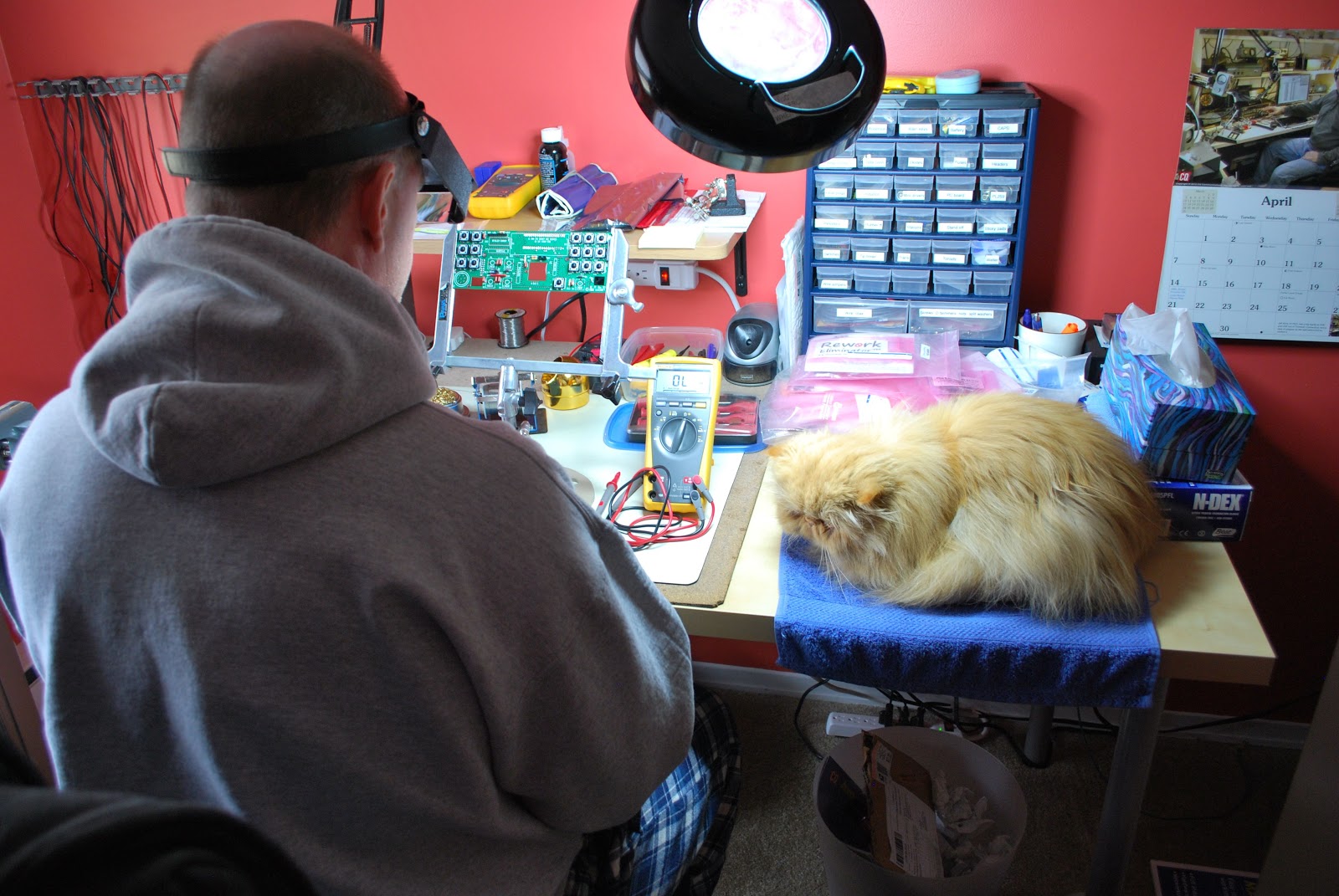 |
| Oliver is keeping an eye on things |
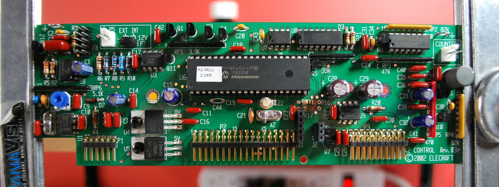 |
Control board completed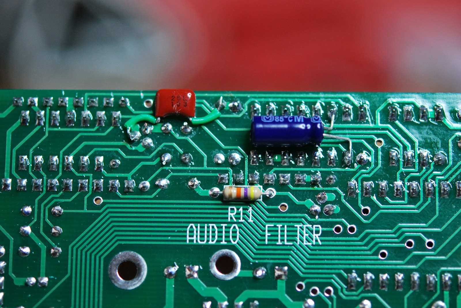 |
As was said I am in the process of building another Elecraft K2 and I have another blog that deals with the build. I wanted to blog the progress but also highlight other areas such as toroid winding, what was needed to be a kit builder and so on. There are specific posts about the K2 build it self making mention of tricky sections of the build and how it was handled. It's now time to see if the bands have come alive!!
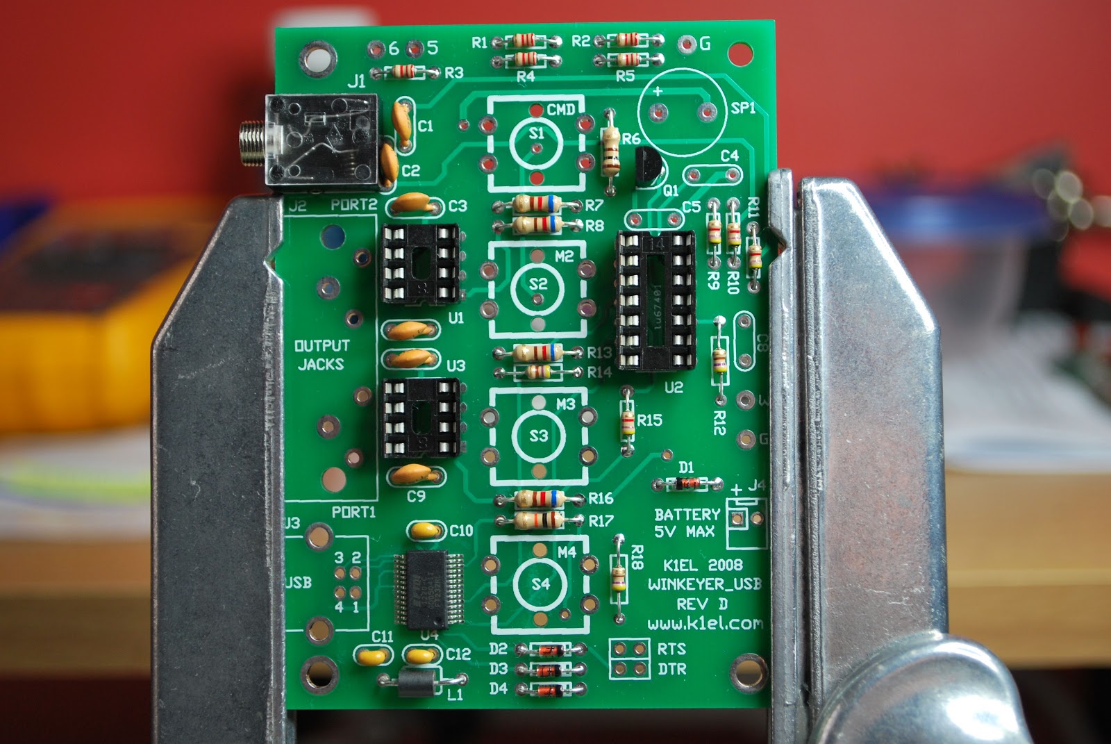
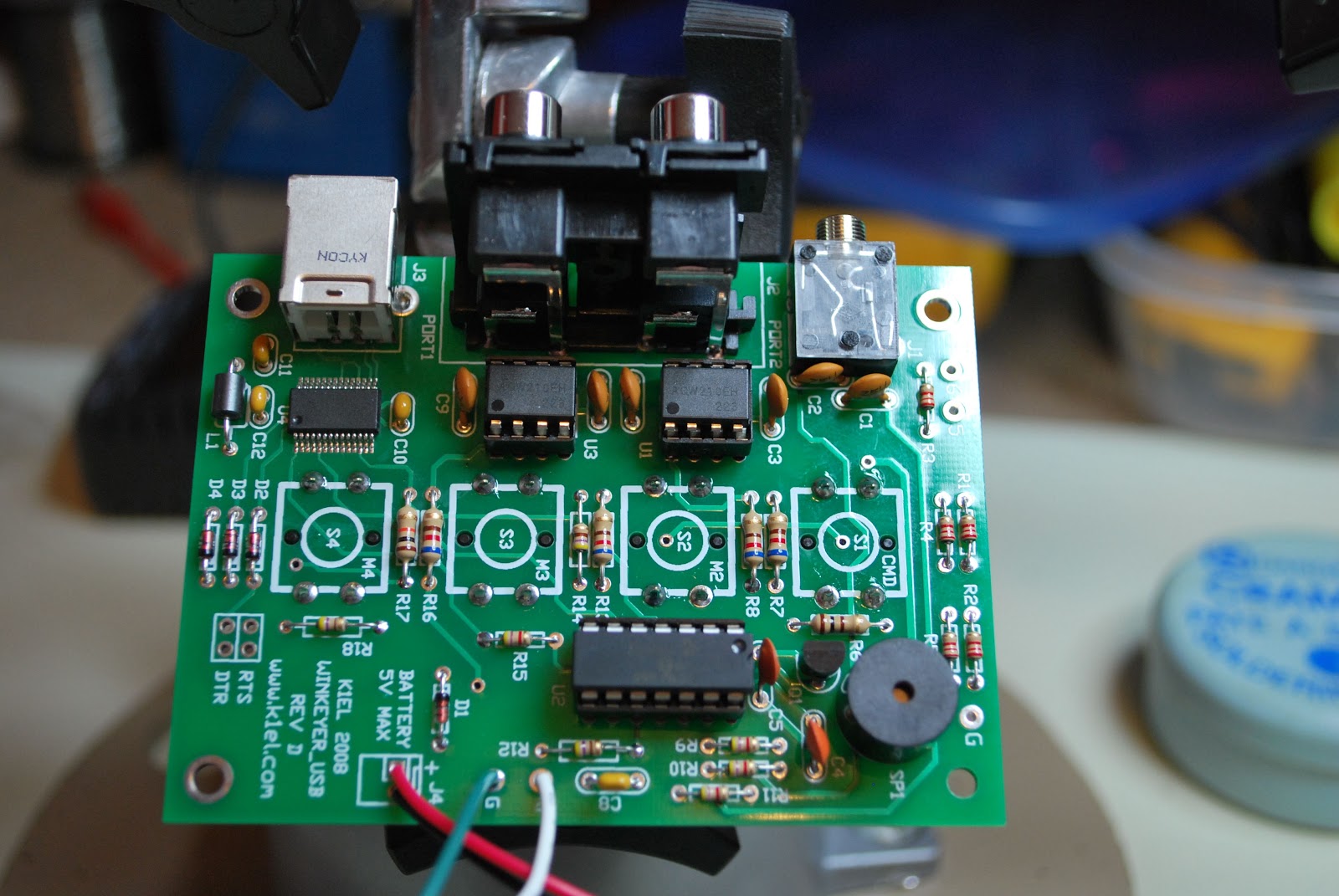
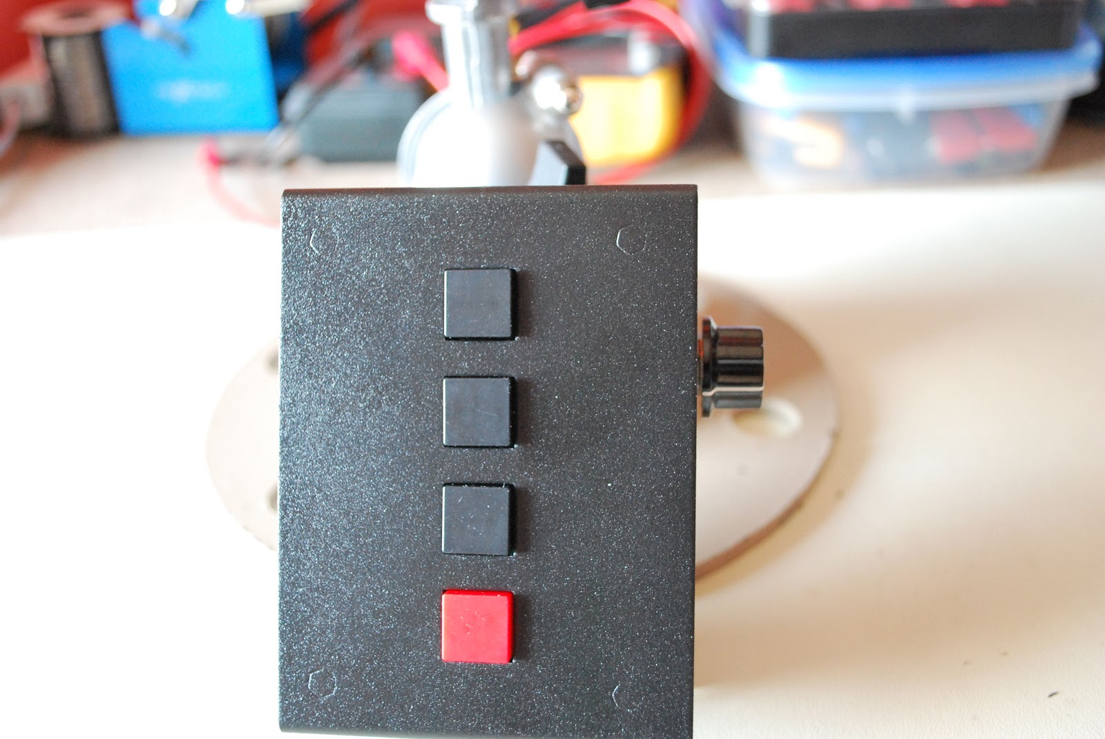
K1EL Winkeyer USB complete
 |
| K1EL Winkeyer ready for action |
 |
| The first day of assembly |
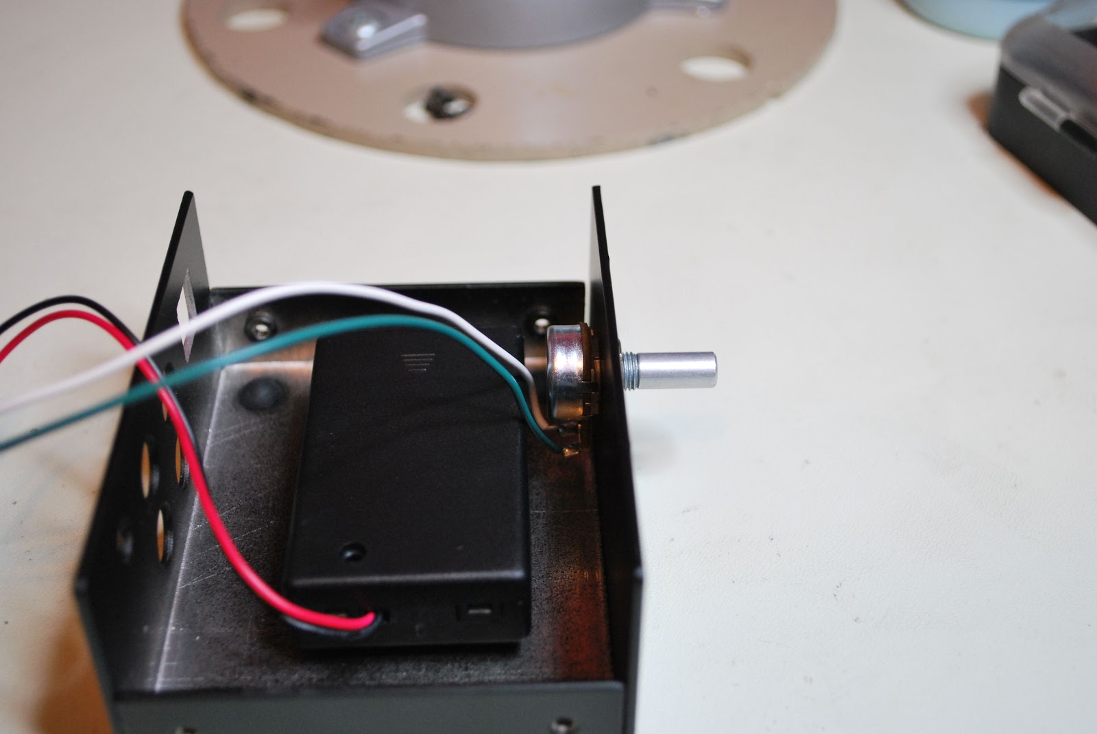 |
| Battery holder |
building will be a smooth experience. Take your time building the unit, it's not a race as certain components such as USB connector, 1/8 jack and 4 way RCA jack should be mounted with care. This makes the final assembly of the two metal covers fit without any surprises.
 |
| Kit complete |
1. There is a 10k potentiometer and the shaft was just a bit to long and I had to trim it. This was only for looks as I did not like the knob extended away from the keyer.
2. No hookup wire was provided to go from the potentiometer to the board. This is no big deal either as I did have the wire...but.....it would had been nice to include it in the kit.
 |
| Pot before mod |
 |
| Pot after mod |
Homebrew Buddistick Project – Part 1
This is the first post about my project to build W3FF’s Homebrew Buddistick antenna. This is Budd Drummond’s design which is documented on his homepage. The plans for this antenna are on his web site.
I am a new Ham Radio Operator and am just getting my feet wet with HF. I have a Yaesu FT-857 sitting in a box waiting for a power supply and an antenna to get me on the air. I wanted to build an antenna that would be fairly easy to make as well as not very costly. After a fair amount of research, I settled on this for my first HF antenna. It looks like it’ll be easy to set up and take down as needed as I intend to use it for Field Day, and any other times I am out in the field. I really don’t intend on being tied down to a home station. I am going to build up a portable station of some sort.
My first step was to collect the parts. I spent a few weeks picking up bits and pieces. This first picture is what I bought in terms of hardware components. I did not find the 1 1/4″ bolts that Budd specified, so I bought 1″ and 1 1/2″ versions and will figure out which to use as I make that part of the antenna.

The PVC components are pictures below already cut and drilled per the instructions.

The next step that I am going to tackle is cutting the wire for the coils and wrapping them.
In the following picture, I have started wrapping the coils. A couple are done and I still have a couple more to do.

While doing this, I found that it’s important to wrap the coils close together tightly as the longer coils were pretty tight getting all all the wraps in between the holes that were drilled for the tag ends to go through. The easiest one was the 20m coil. The toughest was the 60m coil with 82 wraps. After wrapping the 60m coil, I had to work the wire wraps down again to get all the wraps to fit.
I’ll post more as I go . . .

A new battery charger……………
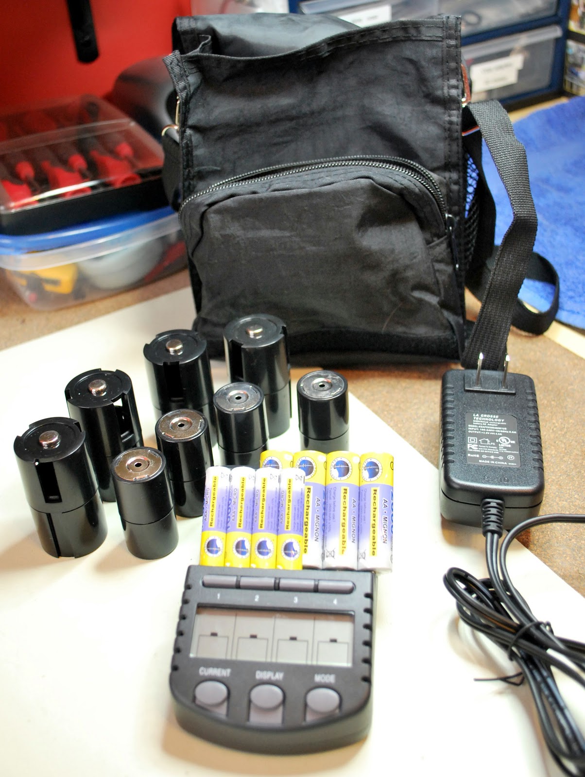 |
| It came with all this |
unit....not bad for 60.00 and 2 day shipping to boot.
So what is so great about this charger, each cell can be charged, discharged/charged, refresh/charge or finally test/charge. Each cell can have it's own custom type of charge done to it. The charging rates can chosen from 200mA to 1800mA and again each cell can have it's own charge rate. The unit will let you
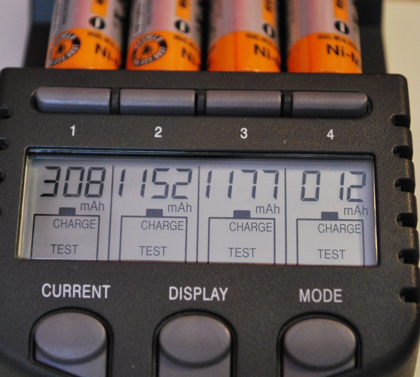 |
| Charge and test mod results |
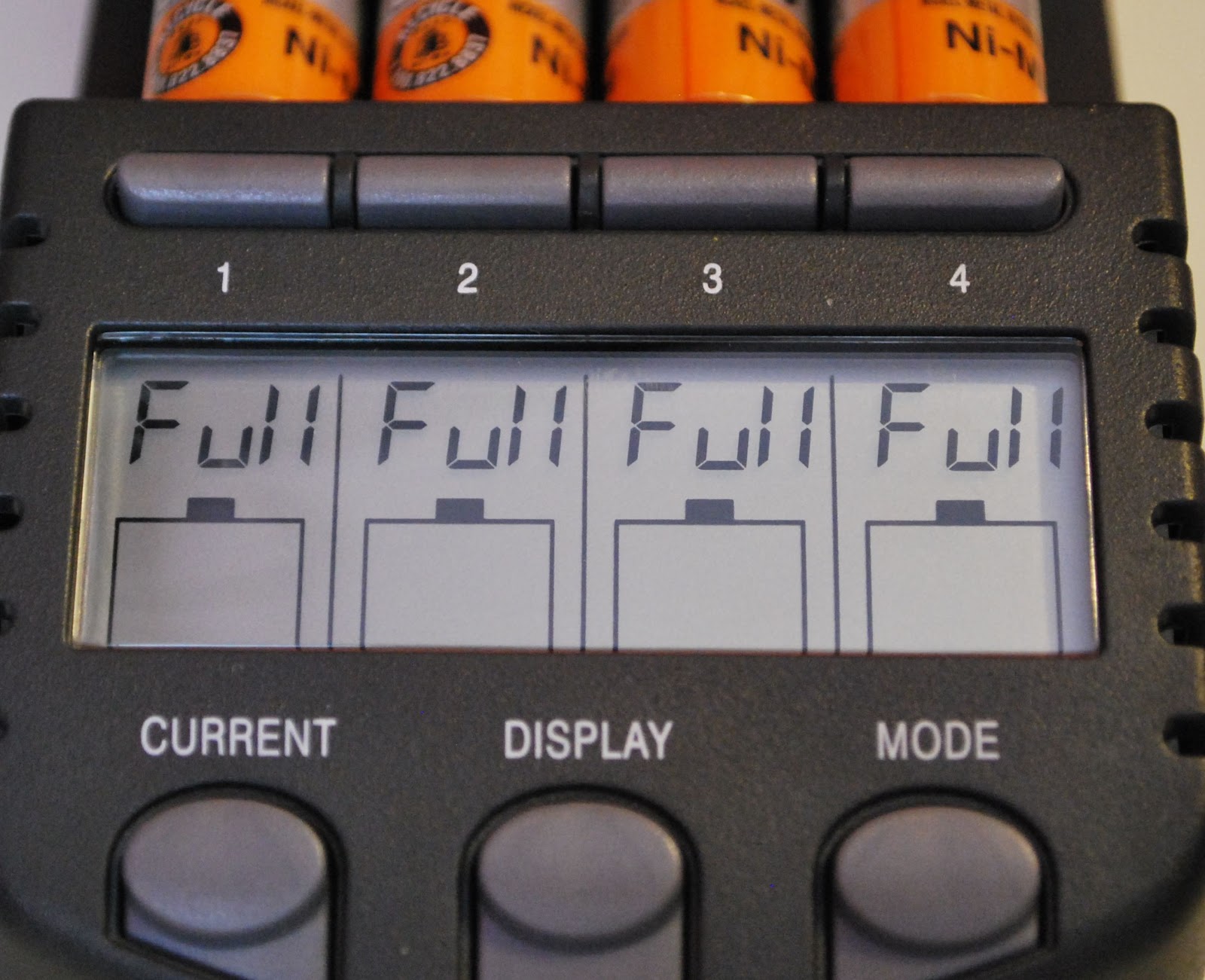 |
| TEST/CHARGE complete |
With this charger you are able to get the most out of your not so cheap rechargeable batteries and make your hard earned money go as far as it can.
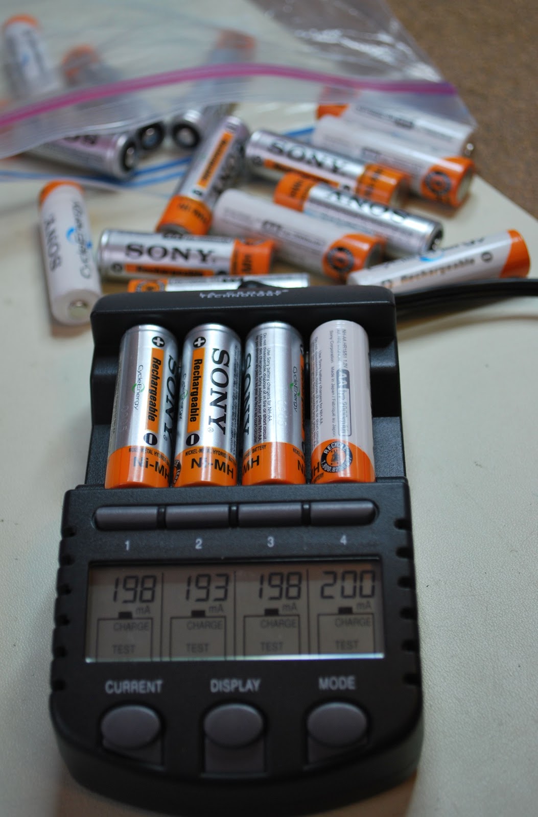 |
| And the testing goes on |
Homemade 2M Yagi Tape Measure
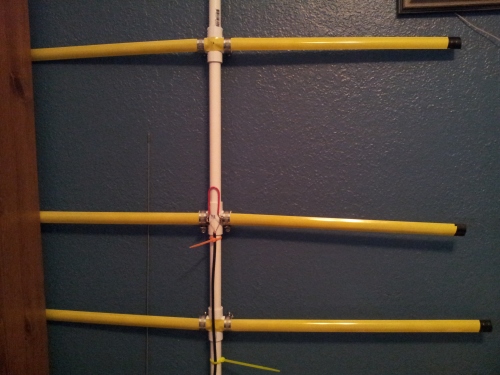
I made my first antenna. It’s a 2 meter yagi using the recipe on this web page: http://www.ccars.org/Projects/TapeYagi/index.htm
It works but not quite as well as I expected. After my first test, I found a stray strand of wire shorting the center and shield conductors where I separated them. I fixed that and am waiting to re-test. I’ll follow up with the results from that test.
After fixing my stray wire, I got much better performance and it works great!

How do you sell an Elecraft K2
 |
| My first K2 serial 6613 |
developed a kit that allows the K2 to be setup and ready for any add on you want to put in the K2. Let me clear the waters a bit......if you build a bare bones K2 with no options but later you want to add some options, it my require you to remove some components from the K2 in order to add the option.
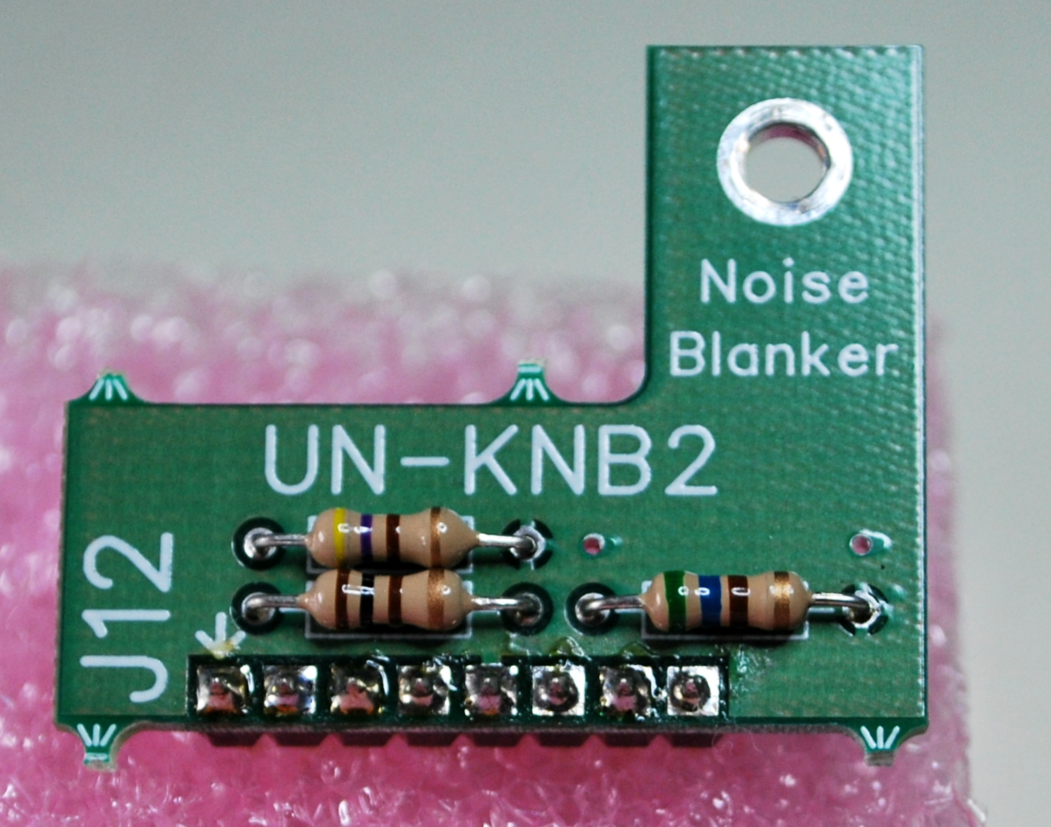 |
| NB rework board top view |
From the post I received great suggestions on options that should be added while building the kit. The one idea I am leaning toward is to just leave the radio "option free" and
 |
| NB rework bottom view showing header |


