Posts Tagged ‘Projects’
 Lots going on….but no on air time.
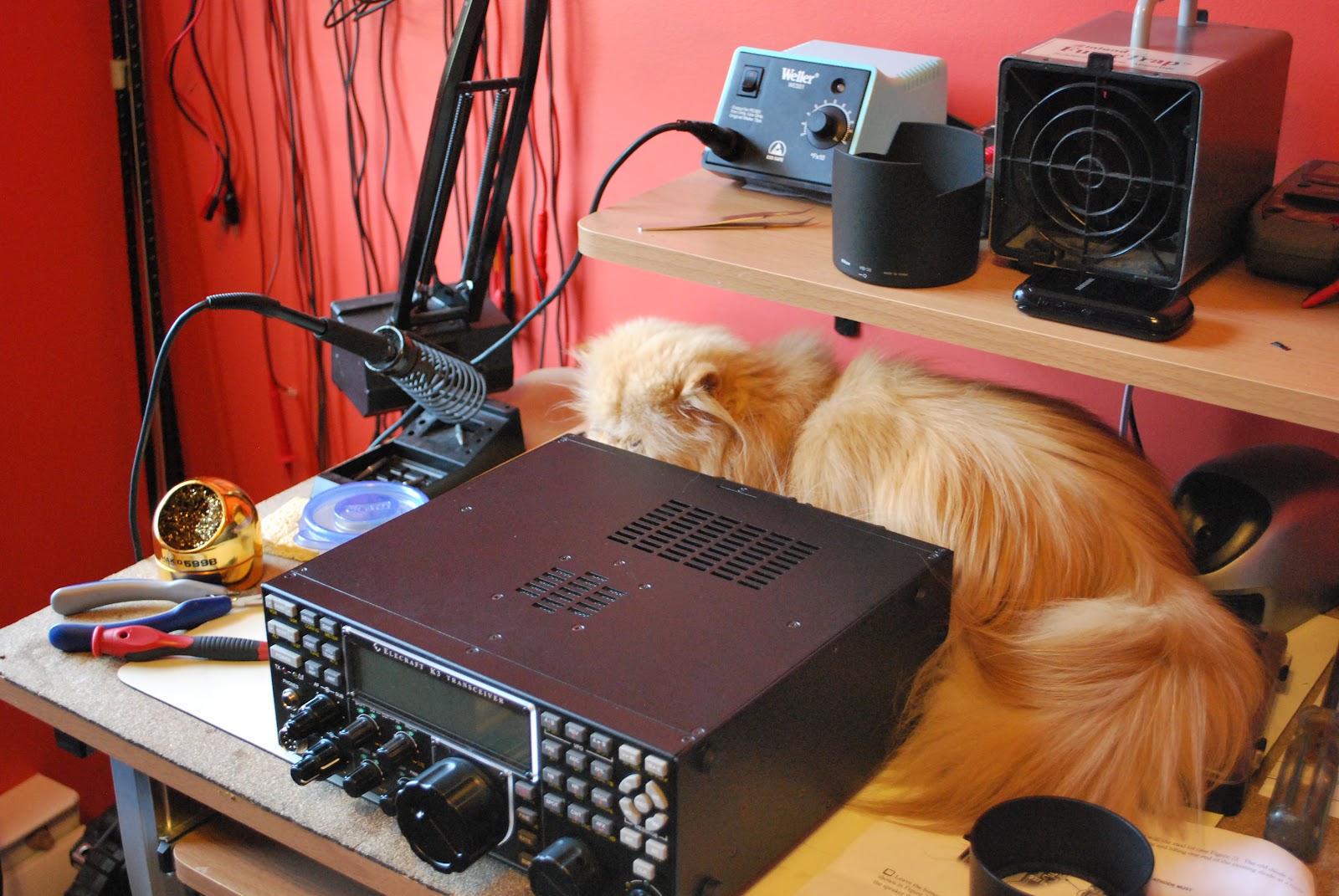 |
| No room for Oliver on the old desk |
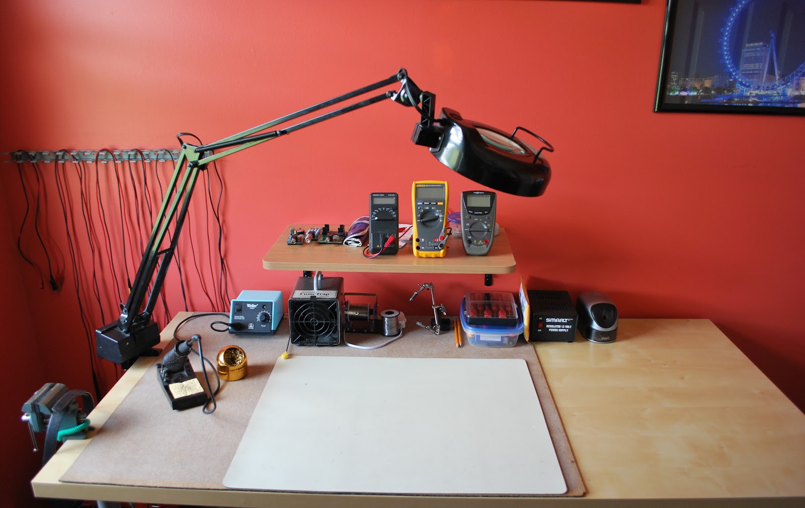 |
| The new desk twice the size |
electronics store the other day (picking up parts as a result of a destructive test going wrong) and saw a neat 9 volt battery holder I am going to add to the QRPometer case. I also have sold all of my items that were up for sale and I have the funds to order my Elecraft KX3. It's not going to be here until October but that will give me time to read the manual and set up a place for the radio. While on that topic with some of my funds I went online to Ikea and purchased a much needed larger table for my kit building. The old desk was just way to small and things were falling off. The old table was actually a computer desk and it now is off to the side in my shack with an iMac (27 inch screen) one that Julie donated to me!!! So the new Elecraft KX3 is going to run on Mac software.
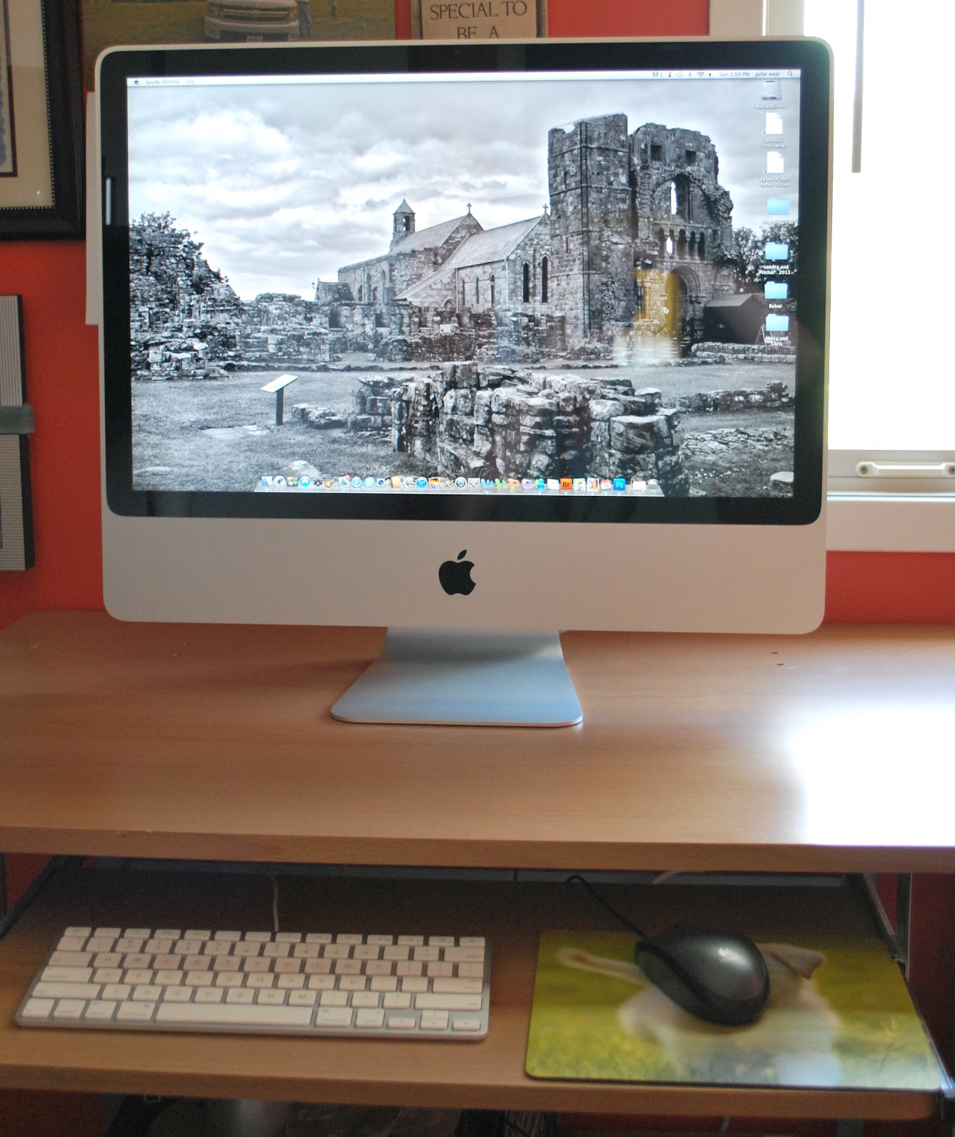 |
| iMac waiting for the KX3 |
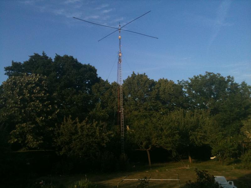 |
| F8DGY's antenna |
Soon there will be a new KX3 coming to town…
 |
| Elecraft KX3 |
To help raise the funds for the new Elecraft KX3 some items here at the shack have to go up for sale....including my beloved KX1!! I have a new page with all the "for sale" items on it have a look and see if anything there can find a home in your shack. Yes Yes there was a post on my blog regarding my Elecraft K2 and how it was just fine (and it still is) and I did not need a KX3........BUT the bug has bitten.........and it has gone from a need to a want!!!
Other goings on at VE3WDM
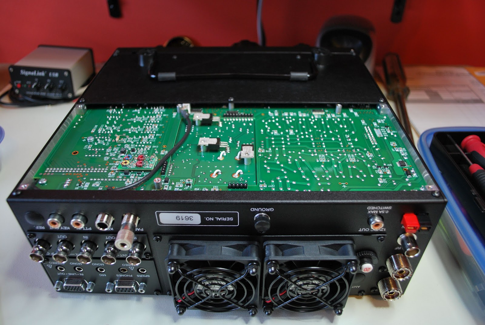
When I ordered my Elecraft K3 some years ago I had it outfitted with the 100 watt module....as most you know I am not a QRO op....not that there is any at all wrong with QRO but for me QRP and QRPp is the best option considering my stealth operation. So the 100 watt module (KPA3) was put up for sale and sold in 1 day to help fund my KX3. Now my Elecraft radio is what is called a K3/10 (10 for 10 watts max output). Removing the KPA3 meant taking out my Sub receiver from the rig, the NB board along with some jumper cables. When events like this come I just hate opening up a 5K rig and playing around with the "stuff" inside. All went well and it's back together and working just fine.
I tried and I tried and tried to contact CY9M but it just did not work out that DXpedition is not shut down and it just was not meant to be. This weekend is the NAQP CW contest it starts at 2pm local time and runs til late evening. I am going to give this popular contest a go considering the not so good propagation lately this local contest will be fun even with max 5 watts.
I have an Elecraft K2 with the internal battery pack and up to this point I really have not been charging the internal battery to optimize its life. Some time ago I came across A&A Engineering They offer a great charger for the Elecraft K2 internal battery. I ordered it and it arrived in no time it's waiting to be assembled because....surprise surprise.... I ordered the kit!!
As for my kit from DIY electronic kits the USB 0-500mhz USB power meter kit has been soldered and is all together BUT is seems it has to be calibrated as the output of the rig is not even close to the readings I am getting with the kit. I have emailed the DIY electronics company over and over again but nothing.......seems that was 90.00 down the drain. I am going to keep it up and if I can I want to find a phone number I will then call them and demanding a refund!!! On an up beat note I posted a short time ago about a kit that I ordered and put together call the QRPometer. This kit is a great QRP watt meter and SWR meter but it only goes done to 500mW's..........now for most of you that is just fine but not here at VE3WDM!!! I like to operate now and then at QRPp levels. This means I need a meter that will give me good and reliable wattage readings from about 10mWs up to 100mWs. This was the reason for me ordering the USB 0-500mhz USB power meter it brags of getting down to the low mW levels..........IF YOU CAN GET IT TO WORK AND GET THE DAM TECH SUPPORT TO EMAIL YOU.........take a deep breath......ahhhmmmm.........ok Im back. Talking with the 4 state qrp group (those who produce the QRPometer) I am told the meter can have it's decimal place changed!!! This would give me the QRPp readings I need. This is a project that is now in the works and I will keep the blog readers posted as to it's progress.
As for my kit from DIY electronic kits the USB 0-500mhz USB power meter kit has been soldered and is all together BUT is seems it has to be calibrated as the output of the rig is not even close to the readings I am getting with the kit. I have emailed the DIY electronics company over and over again but nothing.......seems that was 90.00 down the drain. I am going to keep it up and if I can I want to find a phone number I will then call them and demanding a refund!!! On an up beat note I posted a short time ago about a kit that I ordered and put together call the QRPometer. This kit is a great QRP watt meter and SWR meter but it only goes done to 500mW's..........now for most of you that is just fine but not here at VE3WDM!!! I like to operate now and then at QRPp levels. This means I need a meter that will give me good and reliable wattage readings from about 10mWs up to 100mWs. This was the reason for me ordering the USB 0-500mhz USB power meter it brags of getting down to the low mW levels..........IF YOU CAN GET IT TO WORK AND GET THE DAM TECH SUPPORT TO EMAIL YOU.........take a deep breath......ahhhmmmm.........ok Im back. Talking with the 4 state qrp group (those who produce the QRPometer) I am told the meter can have it's decimal place changed!!! This would give me the QRPp readings I need. This is a project that is now in the works and I will keep the blog readers posted as to it's progress.
In conclusion I always like to preview my blog post before it has goes "live" and for some reason the post is DOUBLED SPACED I have looked into this but am unable to find the answer..........keep you all posted on this one!!
Hendricks 41dB attenuator built and added to the mix
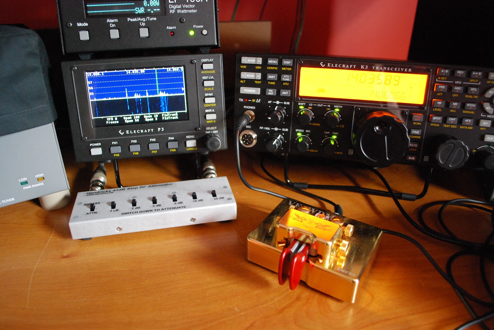 |
| Hendricks attenuator in service |
 |
| Final testing |
Now when I want to use the attenuator it's a matter of selecting antenna B on the K3 and Ant B selected on the DTS-4 and I am ready to go with all the setting on the K3 done.
My goals for the IARU conest
- Have fun and enjoy!!
- Look for DXCC's I do not have so I can add to my ARRL Diamond count.
- See if I can beat my miles per watt record of 45,868 miles.
- Have fun and enjoy!!
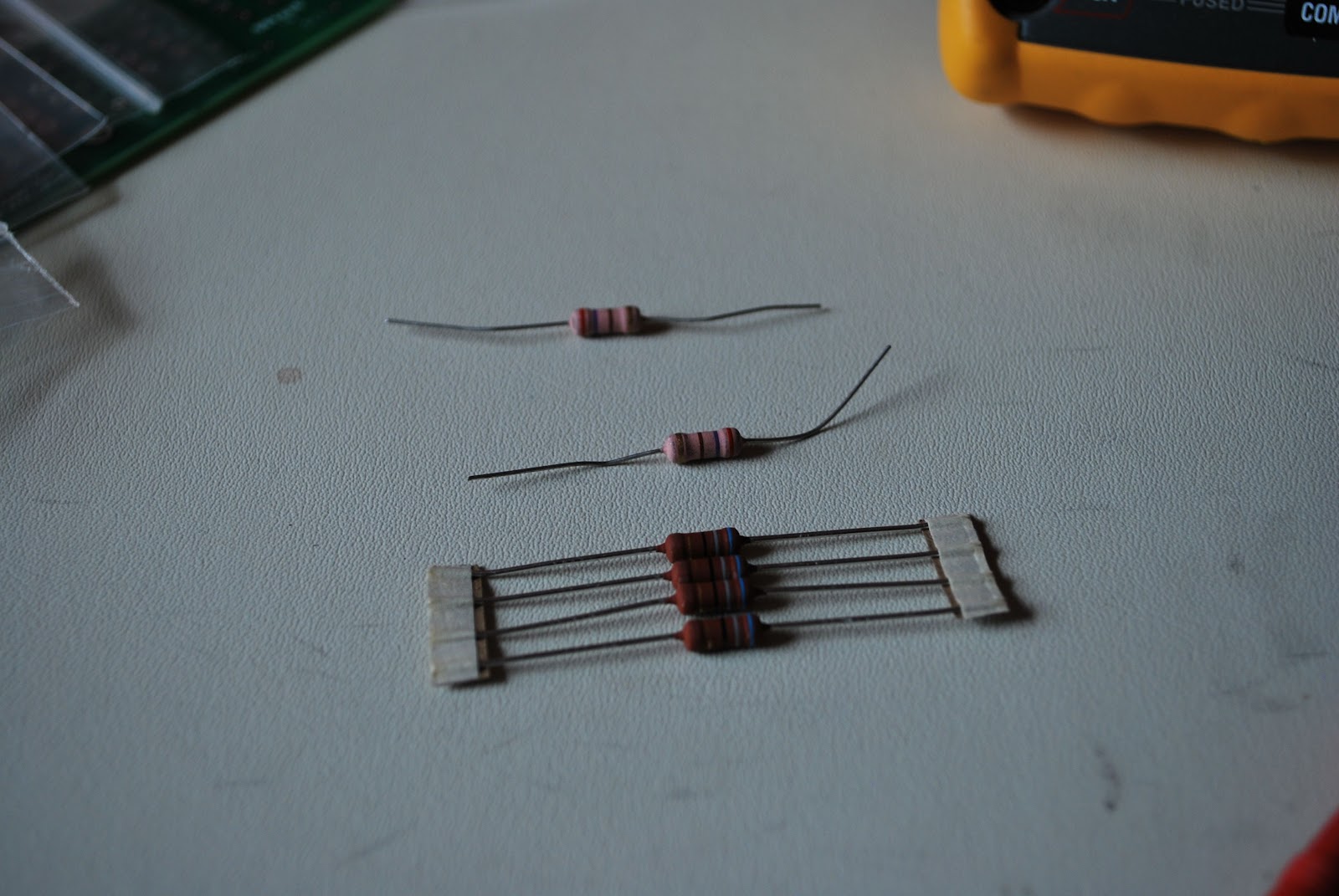 |
| Some of the extra parts |
It’s time for surgery………..
 |
| Ready for action |
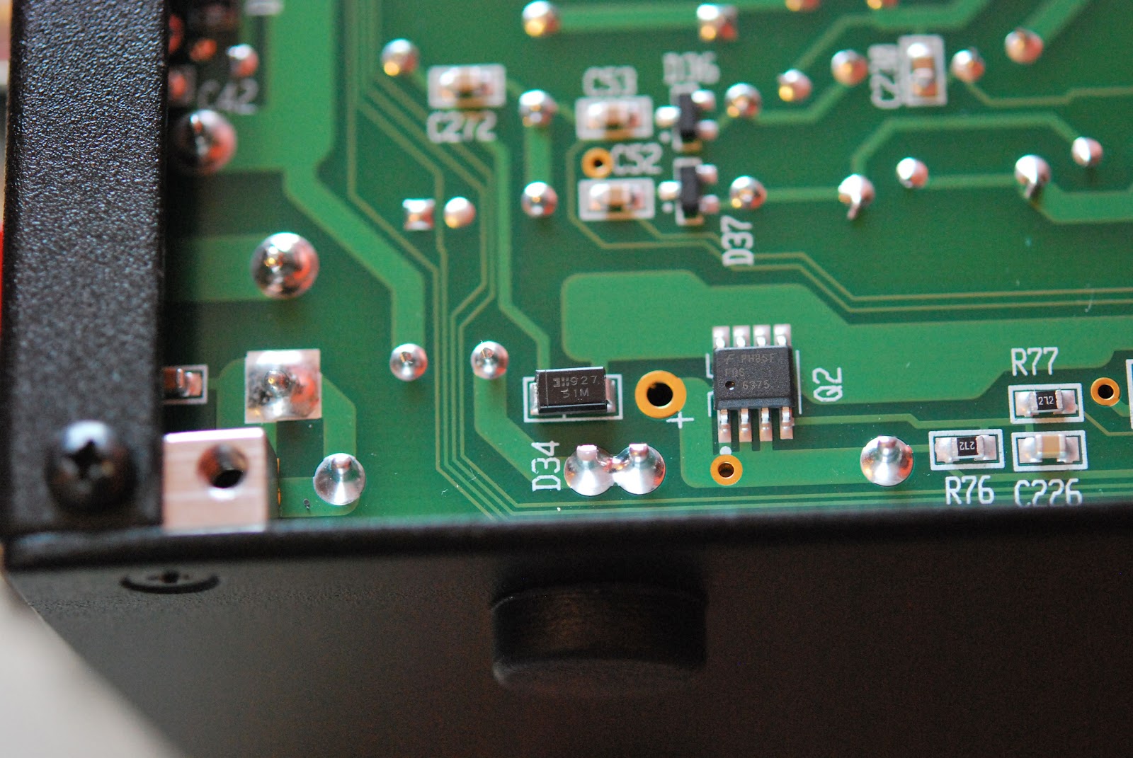 |
| Diode to be removed |
 |
| Fans removed |
 |
| KPA3 removed |
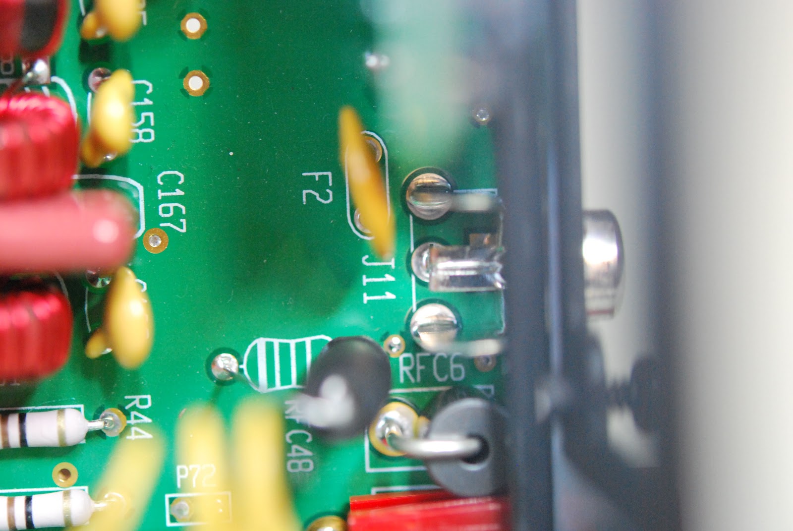
very little trouble. Installing the new one was another story and it did take me several attempts. When all was said and
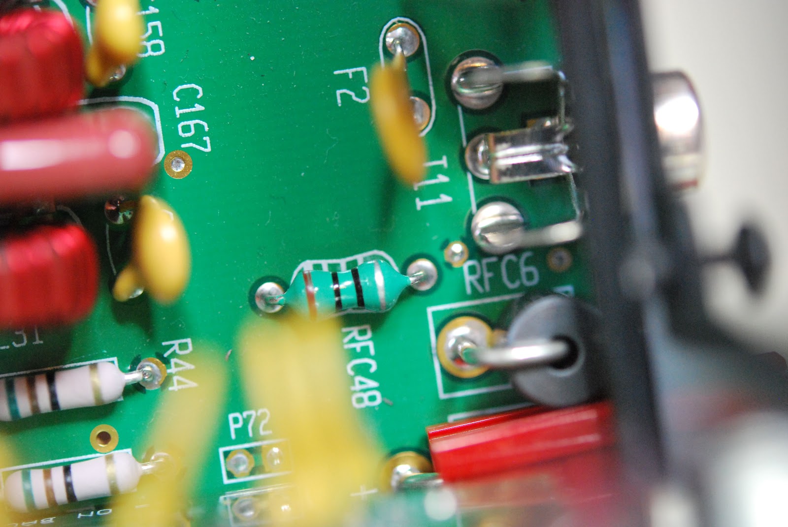 |
| Old F2 and RFC 48 |
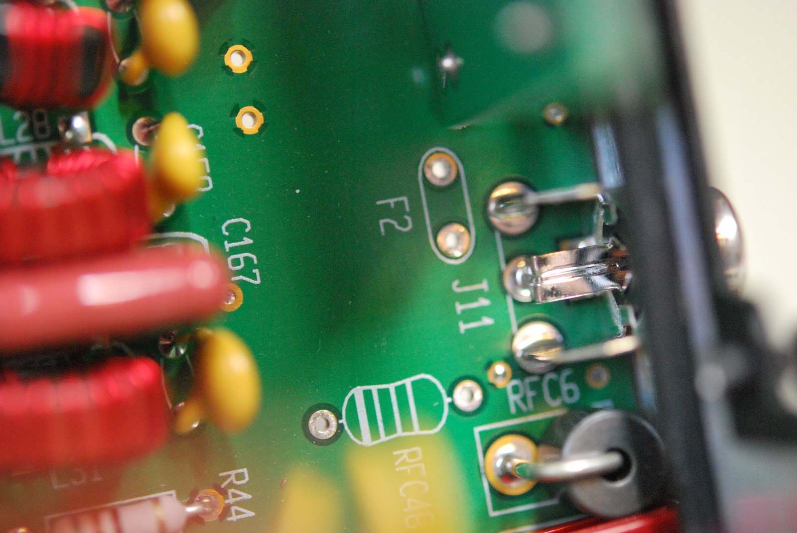 |
| Ready for new parts |
instructions did say the KPA3 unit did not have to be removed if you were very very careful it could be done. Not feeling at all brave out came the KPA3 unit as well. The inductor and resettable fuse that had to be replaced were in plan view and HUGE compared to the SMT diode. I now had to DE-solder the two components and this is were the Hakko 808 was stellar. In under 30 seconds both component were
 |
| Great tool to have |
 |
| back home and working |
 |
| New parts installed |
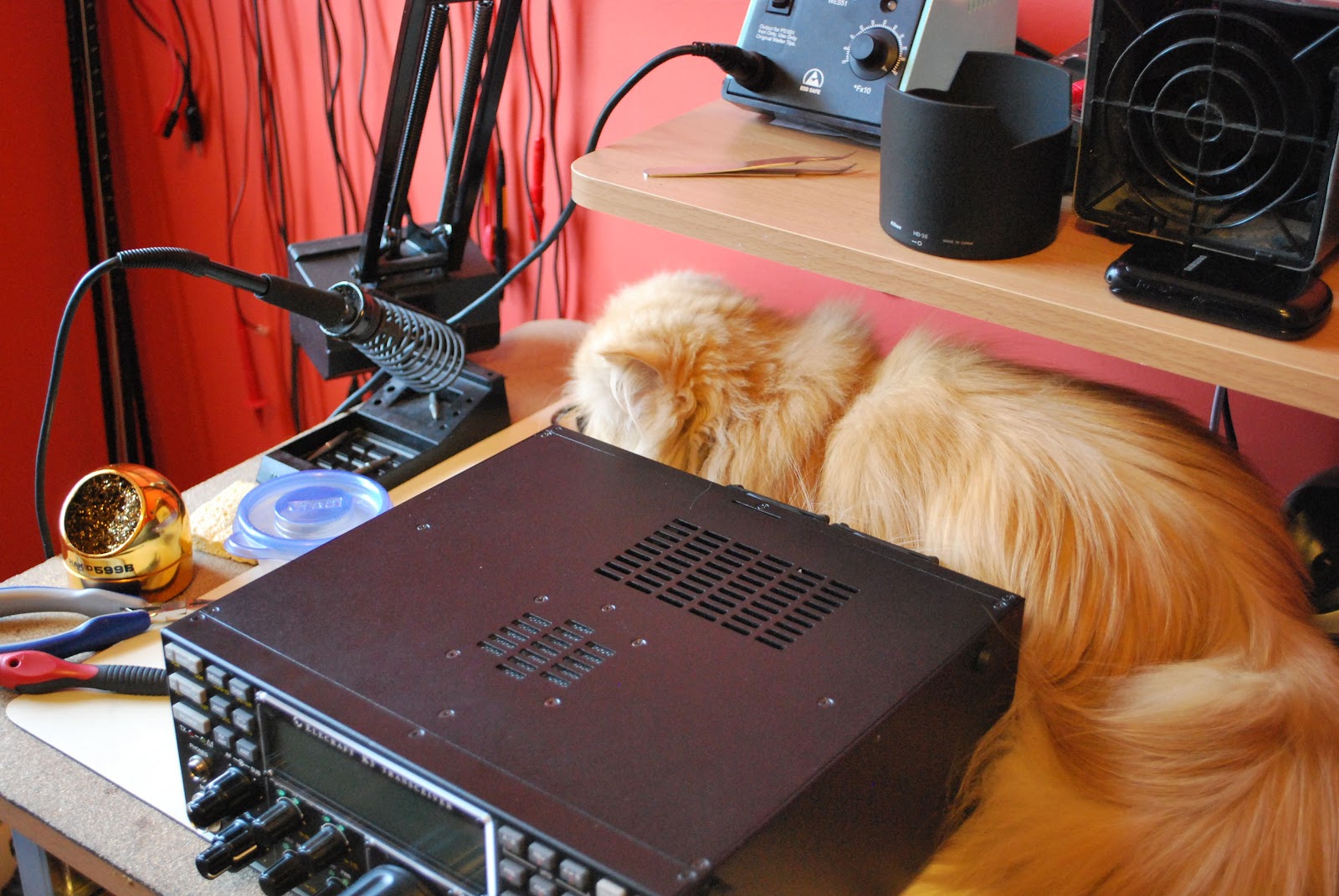 |
| Oliver gives the ok to power up |
Seeing the big picture
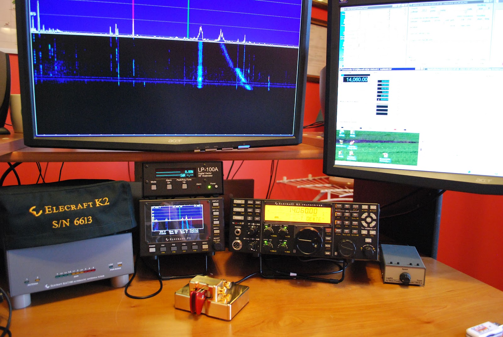
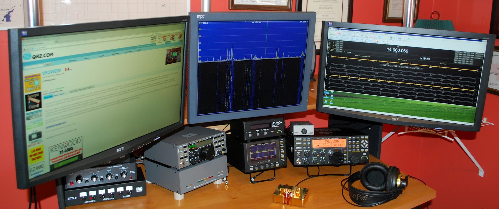 |
| The new setup |
 |
| Old setup |
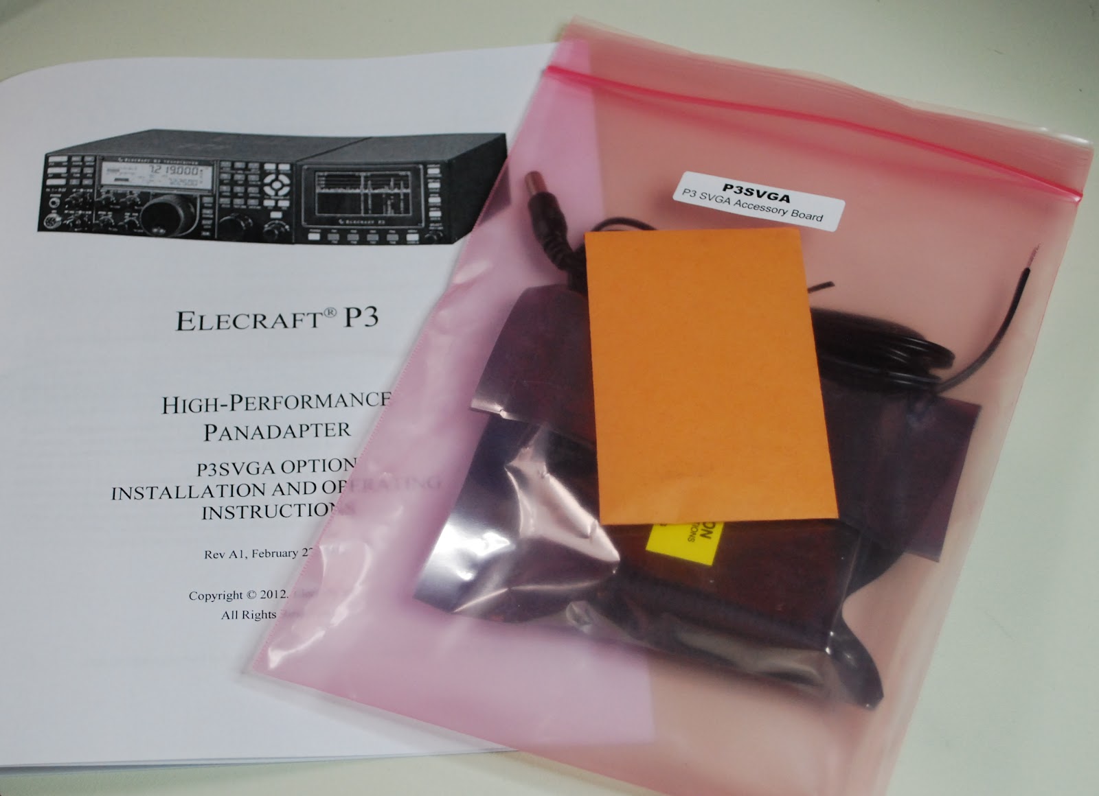 |
| New P3 SVGA |
time to give it a whirl. As a side note I kept a monitor that I was not using but knew I would use it some day. Well the day came when I needed a monitor for the SVGA it's great when I can reuse! The P3 was hooked back into K3 I then powered up the K3 and P3.......BUT the monitor was blank!!! Well lets reboot and try again.....NOTHING..........It them came to me go to the Elecraft site and update the P3's software. I did that and low and behold the monitor came to life with a great looking band scope! It sure is nice to have a scope up close and personal. Now Elecraft has plans to add mouse control, RTTY and CW decoding and more suggestions are piling in. When I added the new monitor I had to do some moving of equipment on the desk. The LP-100A, MFJ 1026 and the LDG switches all found a new home. The monitor was mounted on
moveable arm so when not in use I can move it out of the way. When the final position for all the equipment
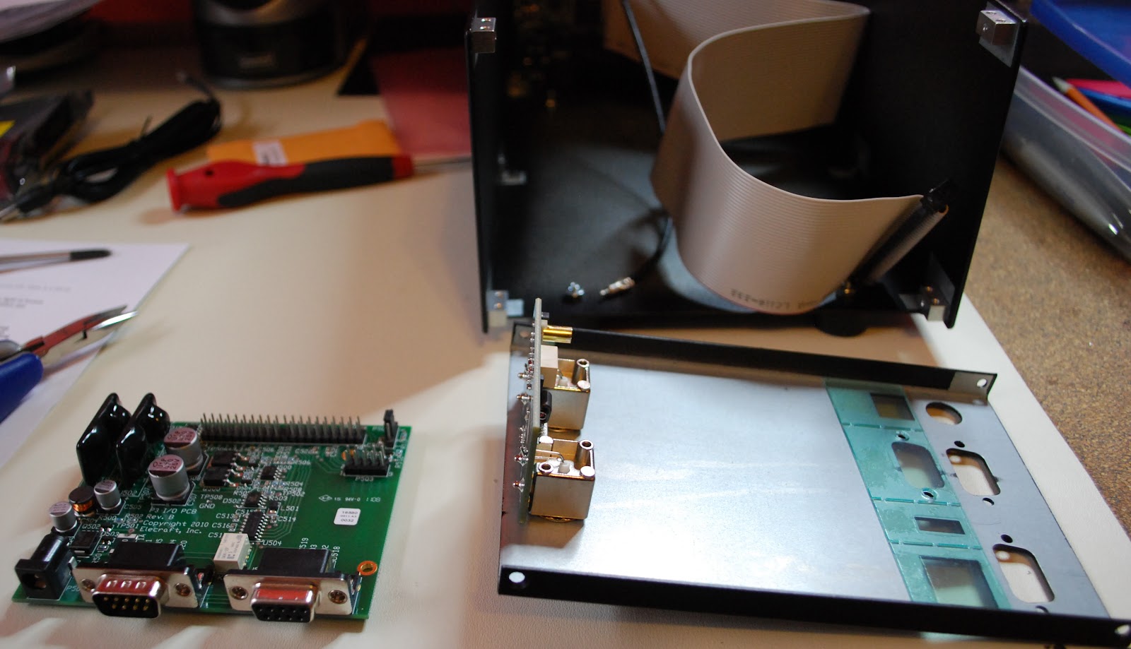 |
| P3 apart and ready for SVGA |
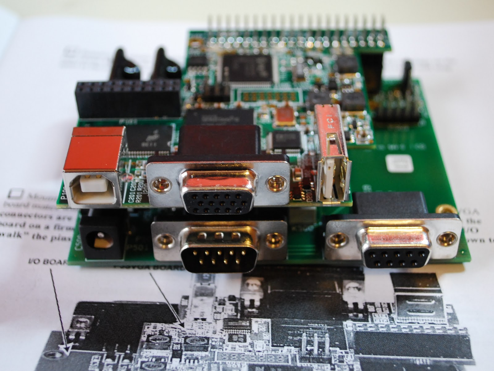 |
| SVGA installed |
labeled cables. My next project is to investigate logging software, radio control software and propagation software. I have been using a hodge-podge of software and I want to clean up the software end of my ham hobby so now it is time to look at some of the free ham software out there....any suggestions would be great!
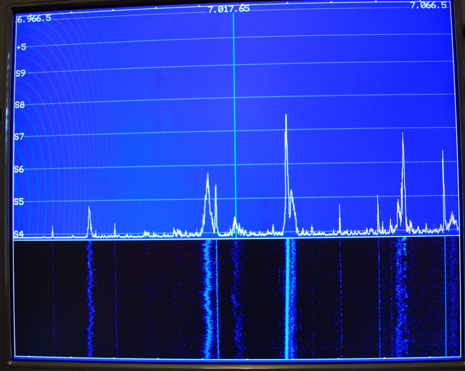 |
| View on the monitor |
 |
| Monitor out of the way |
It’s been one of those weeks………..
Well it's now Sunday and I just don''t know where the week has gone
it does not even seem like the weekend has begun but it's almost over!
It has just been "one of those weeks" I have not been able to get any
radio time in....for that matter really not to much of anything has been
done this week. It has been a busy week but as I look back can't really
say anything was started or completed. As I have reported in my blog I
am
making
my Elecraft K2 portable so I can use it in the car and the out of doors
when the warmer weather comes. I ordered a case from the Powerport store
the case I ordered was the Radio box. It's been 4 weeks now and no case
has arrived I tried to email them regarding this as I was emailed when
the case was shipped. I then read on their site that they do not respond
to emails just (long distance) phone inquires. I wanted to wait until
Friday just to see if it came in....but nothing. I then ordered some
very nice Sony head phones for my portable op's from Ebay....and again 5
weeks have past and nothing. I did email them and was told they were
shipped but they will ship another pair on Monday......It's just been
one of those weeks!
 |
| This is the powerport box without the battery |
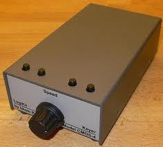
Idiom Press CMOS-4 Keyer………
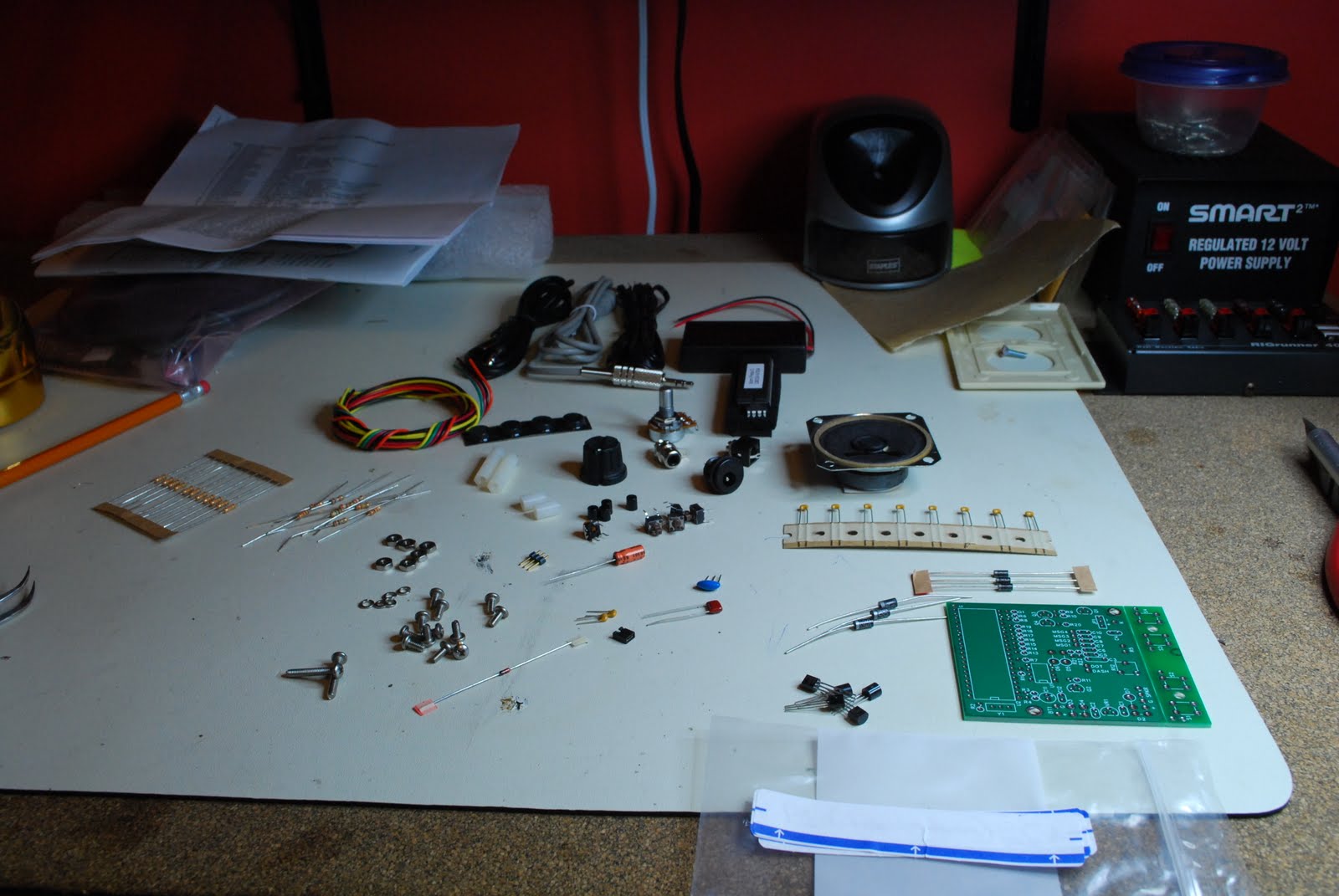 |
| Sorting the parts |
house one day. Anyway, I had read many great reviews about this keyer and has seen some YouTube demonstrations of it was well so I was eager to get it built and running. If you have read in
 |
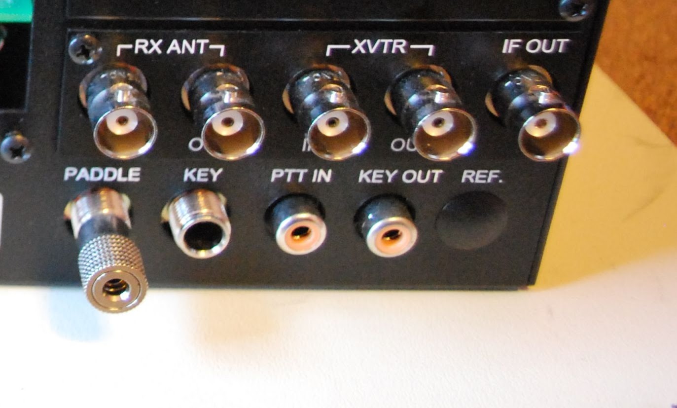
| RCA troubles |
my blog in the past the first thing I like to do with any kit I get is do the inventory of parts. It lets me know all is here as well familiarizes me with the parts. This kit like all the others had part numbers for the parts but for some reason the list gave you a part number and told you it was a 15 ohm resistor for instance and that there were 20 of them and that was it!! So these 15 resistors were they R1, R20, R3 or what, as the kit had other resistors with other part numbers and values assigned to them. So for all the parts I had to go through the build
 |
| Resistor and diode layout |
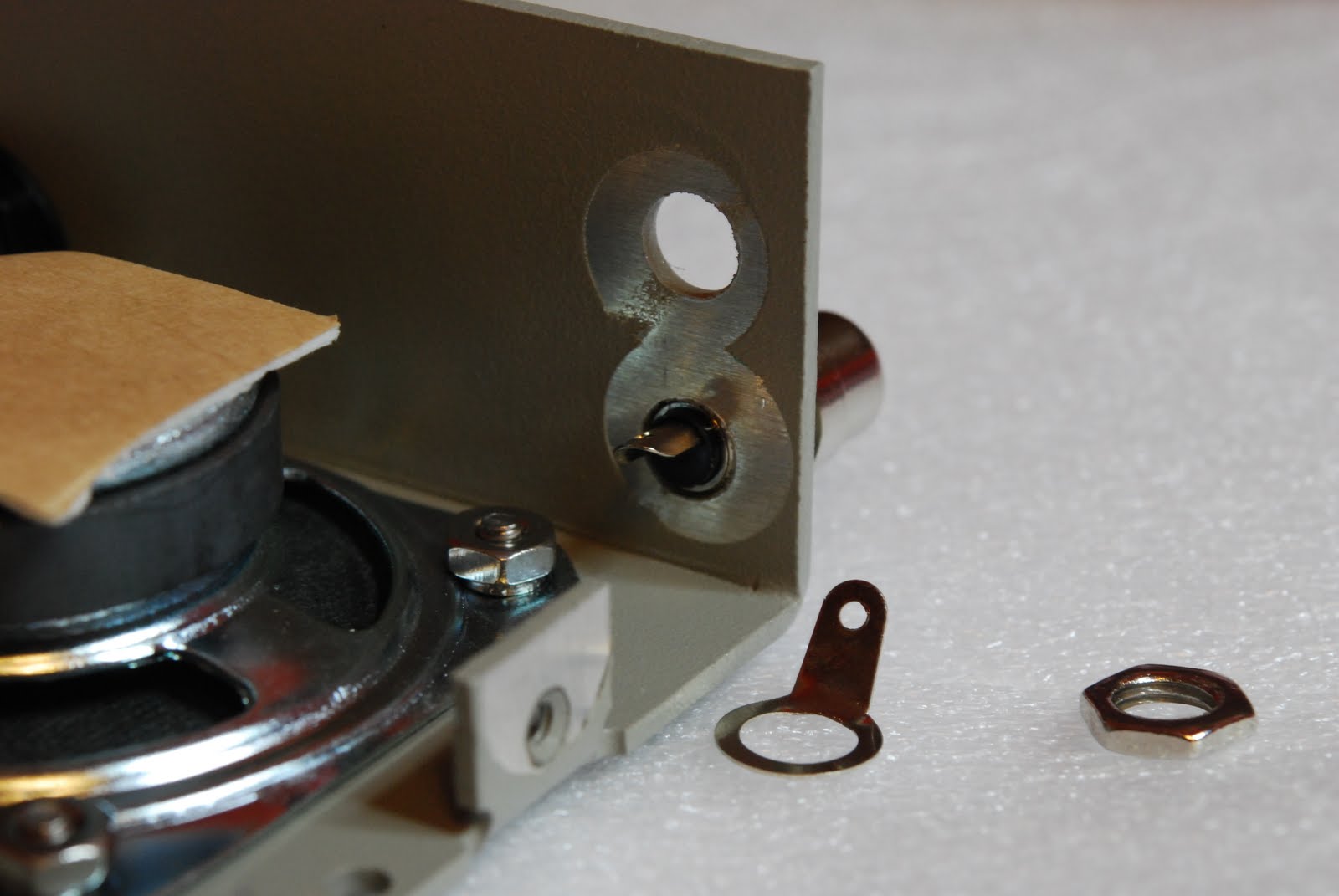
instructions and identify that transistor part number ZC4005 which was a MPSA92 transistor was in fact Q1 in the assembly instructions. Each part had to have this done and I then put the parts in a bag and labeled the bag with the assembly part number on it. The assembly instructions were very clear but more pictures would be very helpful during the build. Steps that involved an odd detail were marked out very clearly and at times in BOLD print. One part issue during the build was an RCA jack that would not fit through the per-drilled hole. This is not a disaster but a bit of a pain having to get the cordless drill out to open up the hole. The only other issue I ran into and should be rectified in my humble opinion is.....there are some diodes that have to be installed and there is a polarity to follow. To make this easier the
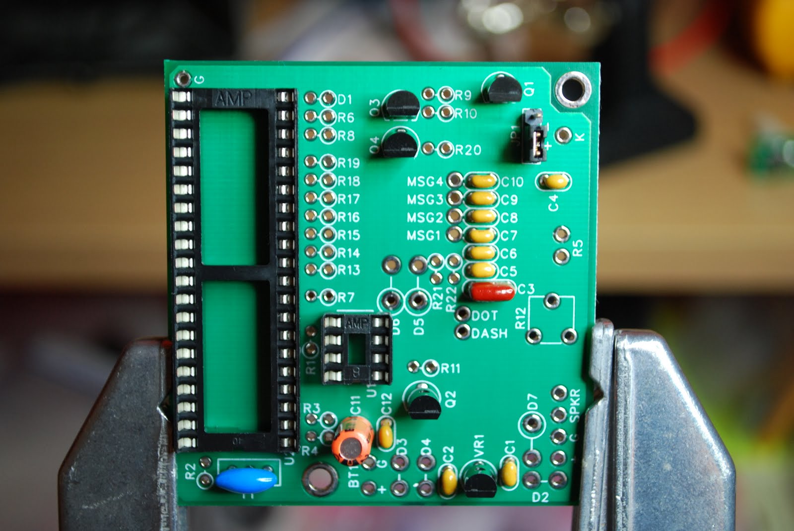 |
| Diode circles missing at bottom |
silk screen on the PC board has a large circle place over one of the diode holes. This is to help with placing the diode on the PC board with the right polarity. Well for some reason there are 3 areas D2,D3 and D4 were the circle did not make it onto the PC board. You are told of this in the instructions and shown on a layout diagram with the proper polarity. How about fixing the boards as well.........Those were the only issues I had with the build. The kit tested great once it was done and if you do order the CMOS-4 as a kit or already built make sure you read the operating manual cover to cover. This is were the kit really shines great detail has been put into the manual. Because this keyer is a real stand alone keyer all programing is done with your key no computer is needed. In the manual you are given exercises to do and make sure you do them!!! This will get you accustomed how the keyer works and how to program it as well. If you are in the market for a keyer this is one to take a close look at. In this post I wanted to include some assembly pictures as I found on the internet there were very few. As you are going through the build a picture would really help at times.
 |
| DC power jack very close to speaker |
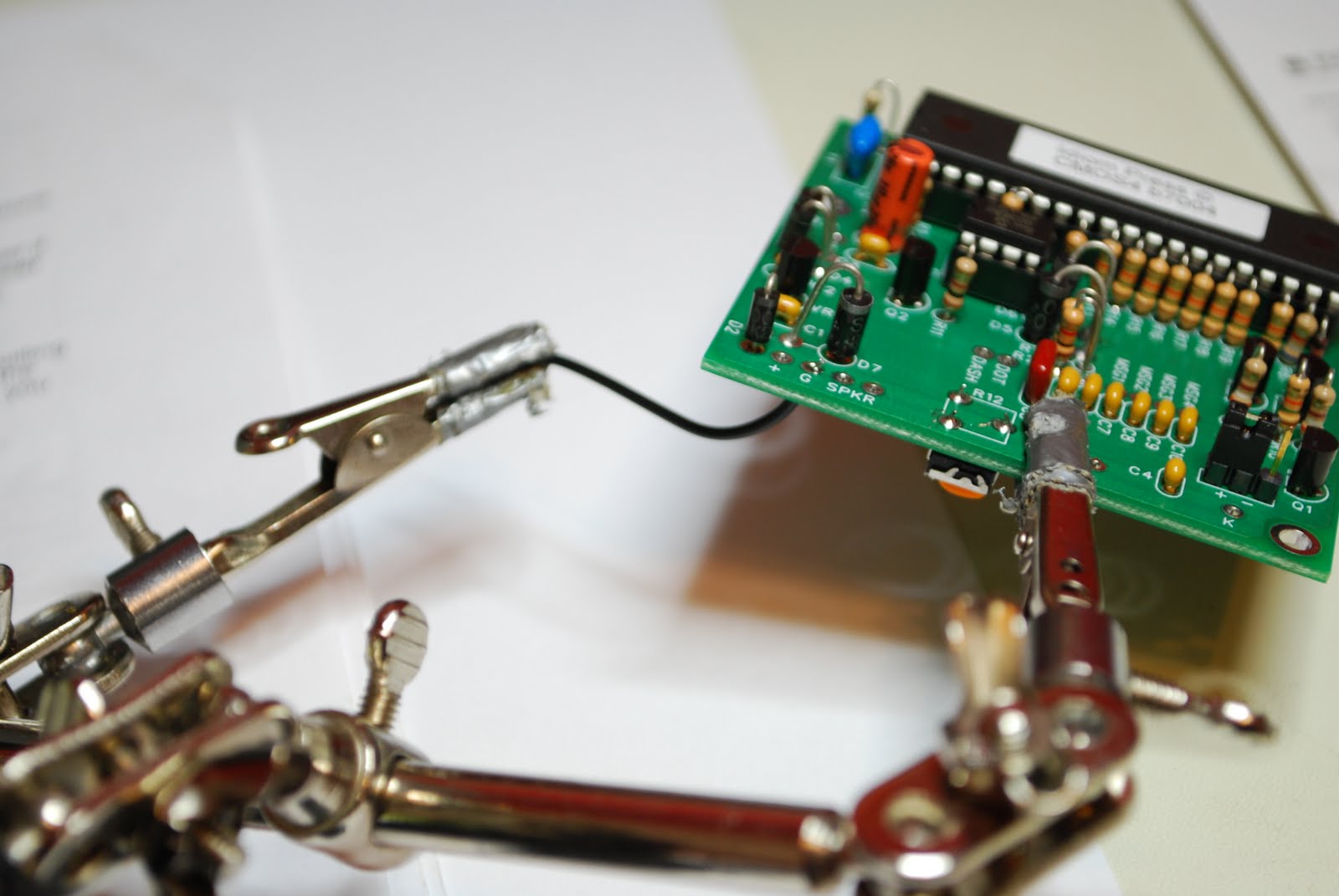 |
| Adding wires to board |
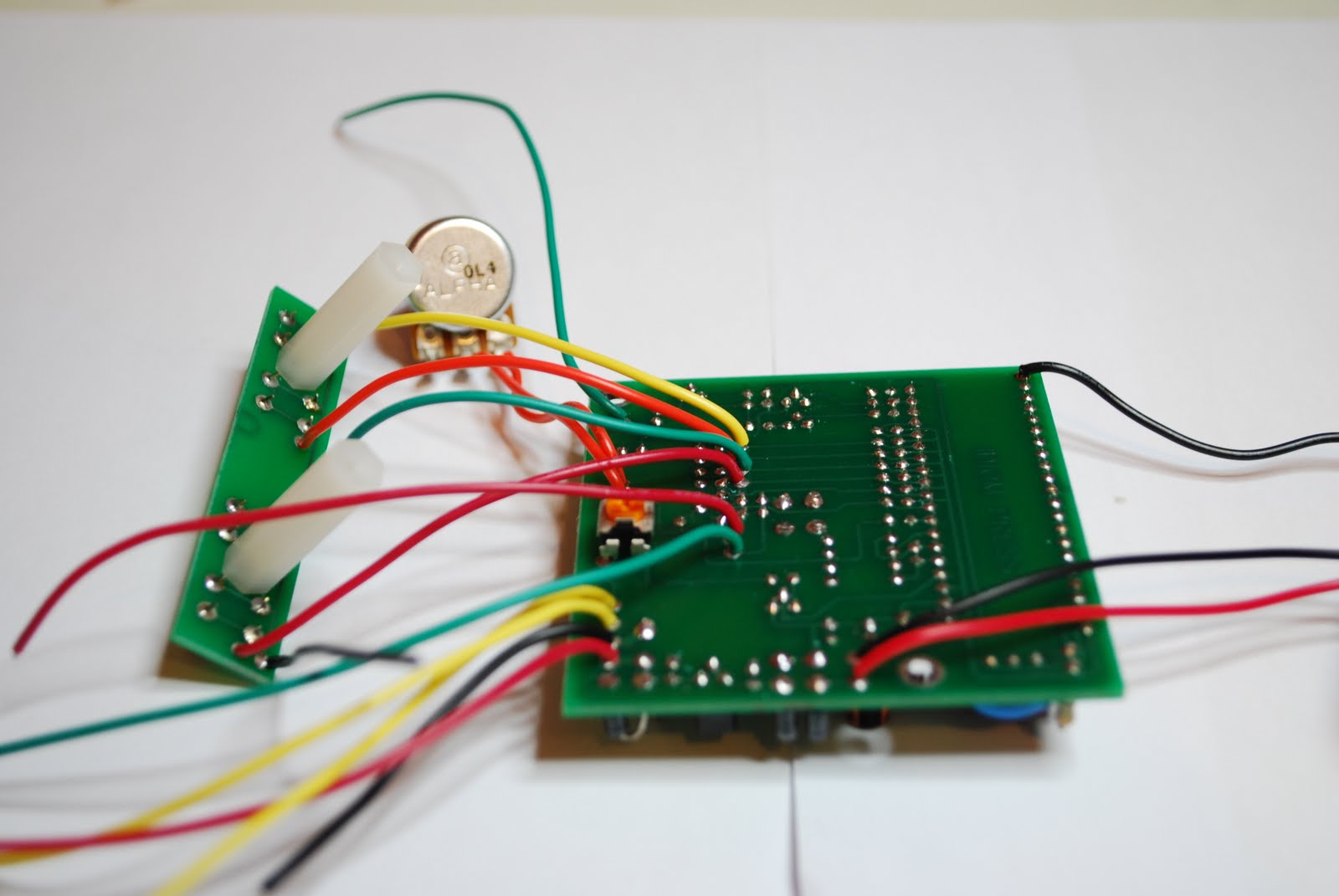 |
| All wires added |
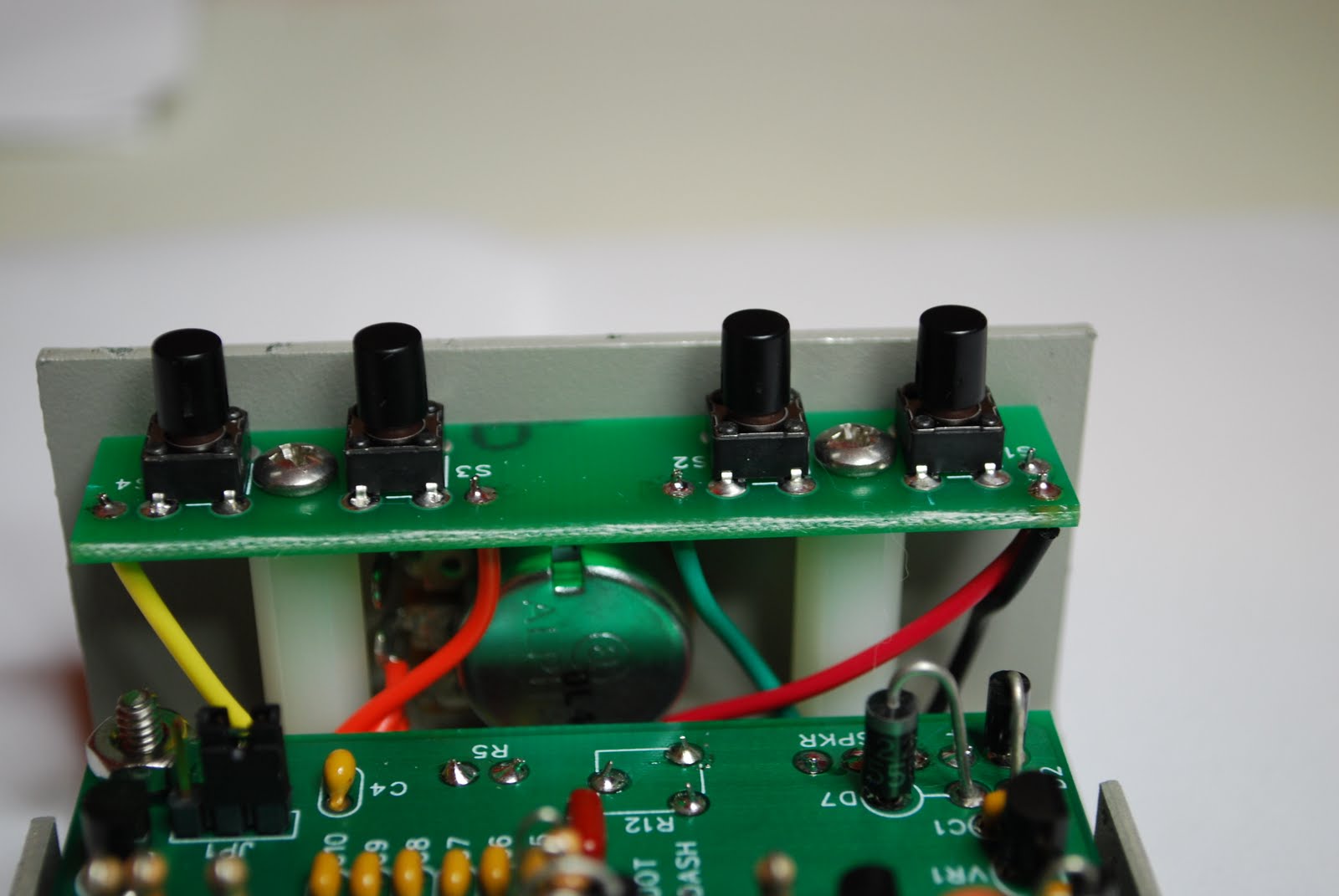 |
| Push button setup |
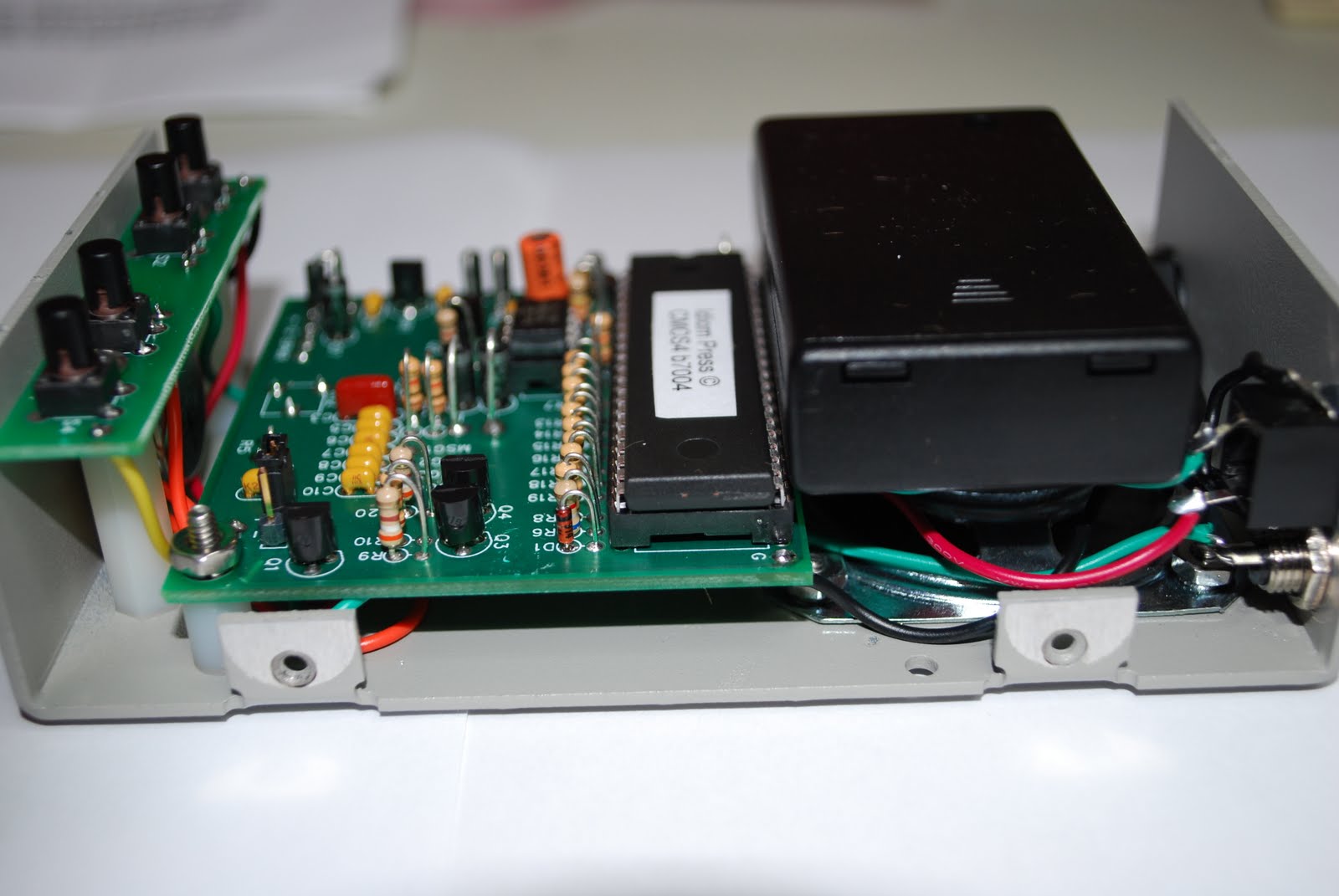 |
| Battery pack added |


