Posts Tagged ‘Test Equipment’
 Antenna testing is hard (II)
This article follows up on this one. The title could also be: doing measurements on hand held radios is hard. Actually, some measurements I did in the past might not be so accurate after all.
Measuring in dBm
If you measure in dBm, what I always did, you assume that the device at the other end is 50 Ohms, just like the manufacturer promises you in the specs. Slowly but surely we are finding out that this is not always the case. As a result I might have to switch to microvolt (µV), a method which doesn’t require a perfect 50 Ohms at the other end.
Can’t we just convert it? 0.5 µV @ 50 ohms = -113 dBm, a piece of cake, right? No. You must know the actual impedance of the receiver if you want to convert from dBm to µV. Erik PE1RQF did some measurements on a few hand held radios to find out the true impedance. The outcome was, well, a bit scary.

If a device is 50 Ohms, the SWR should be 1:1. Only a perfect dummy load and the Marconi RF generator are.
What this means for us
What this outcome basically means is that generating cold numbers on sensitivity and antenna performance are nice, but don’t tell the whole story, or could be misleading.
- Antennas which prove to be the best performers (RX/TX, VSWR), tested under optimal conditions, are not necessarily the best performers on a specific brand/model of hand held radio.
- There are antennas which aren’t 50 Ohms at all, but could very well outperform everything else on the market because your radio isn’t 50 Ohms either.
Do the test yourself
The best example I can give you is this one: take a Baofeng BF-666S, 777S or 888S, use the stock antenna, and make notes of the performance in the field. Try to hit repeaters which are barely in range. If you have a field strength meter, measure field strength when transmitting.
Remove the stock antenna and replace it by a Nagoya NA-701, NA-771, the $3.79 antenna, or the Baofeng UV-B5 antenna. I tried all of these; just pick whatever 3rd party antenna you have. Repeat the tests.
What happened here is that the short stock antenna was the best of the bunch, all 3rd party antennas had a negative influence on the performance of this specific Baofeng model. The same 3rd party antennas mentioned above did improve the performance of the Baofeng UV-5R, often by a wide margin.
Exception to the rules
The funny thing is that reception suffered greatly too. This is quite uncommon and a sign that hand held radios don’t follow the rules. For example, if you just want to receive on 20 meters and your dipole is 2×6 meters instead of 2×5 meters, you would never notice the difference. With your hand held radio however you will.

This Spewed Out of the Internet #25
 Here’s another update of
 interesting important stuff spewing forth from the internet.
I put my two presentations from HamCon Colorado out on the web: Practical Amateur Radio Measurements and Mountaintop VHF in the Colorado High Country . Also, check out Kelly N0VD’s blog posting on the event.
Having trouble finding a repeater to use on VHF? Check out my Shack Talk article on HamRadioSchool.com
KB5WIA provides some good tips on EME operating.
Hans PD0AC addresses the question: What’s the Best Chinese Dual-band HT? For best price/performance, he selected Baofeng UV-B5/UV-B6 (and I agree).
The Noise Blankers continue to publish their Ham Hijinks. Remember: Do Not Take These Guys Seriously. Seriously. Do not do this. Seriously.
There’s lots of great ham radio events coming up this summer. This weekend is the CQ Worldwide VHF Contest, the only “true VHF contest” out there since only the 50 MHz and 144 MHz bands are used. Then there’s the Colorado 14er Event, which includes Summits On The Air (SOTA) activations, on August 4th. (Don’t forget to check out the great new Colorado 14er Shirts!) The Colorado QSO Party is another great operating event, on August 31st.
Remember: There is no such thing as ground.
Think about it: an infinitely large electrical node with zero impedance able to sink an infinite current. Not likely.
73, Bob K0NR
The Mysterious Case of Alternator Noise
When I purchased my 2003 Ford Escape, I decided to install multiple ham radios and a bunch of antennas. Mostly I use a Yaesu FT-8900 FM transceiver for operating on the 2-Meter and 70-cm ham bands. A while back, I started getting reports that I had alternator whine on my transmit audio. I was perplexed because I thought I had done a pretty darn good job of installing the radio, including connecting heavy 12V power cables directly to the battery. (See K0BG’s web page for more information on battery connections.) I really wasn’t sure if this was a day one problem (and no one ever told me about the crummy audio) or something that had just started. My first course of action was to ignore it and see if it goes away. This strategy failed miserably as my FCC-licensed spouse continued to report that I was “whining”. Finally, I decided to put my alleged knowledge of electricity to work. I got out my trusty oscilloscope and took a look at the voltage near the transceiver. There was about 800 mV of ripple on the DC voltage, as shown below.
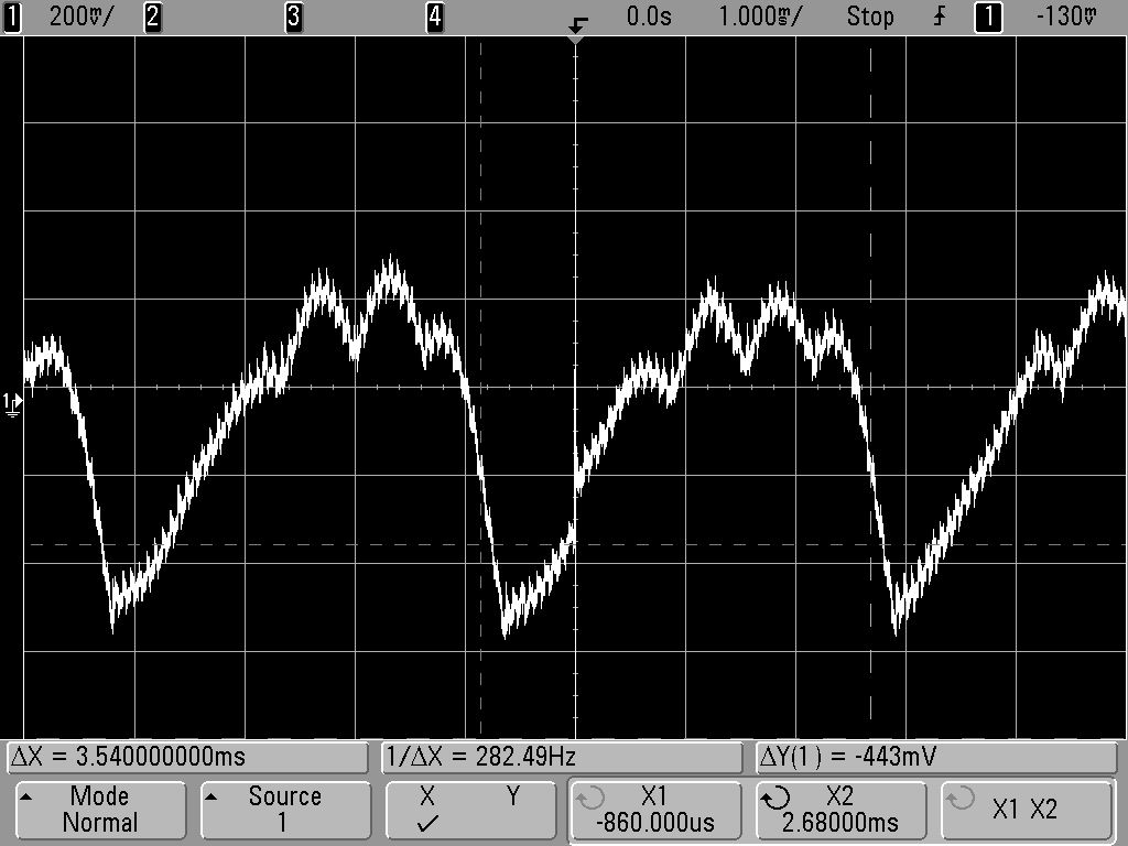
The frequency of the ripple was in the audio range, consistent with alternator whine. The frequency of the ripple increased when I rev’d the car engine, so it was clearly coming from the alternator. I was surprised to find that the size of the ripple did not depend much on whether I was transmitting or not. The transmit current is much higher than the receive current, so I expected the ripple to be worse on transmit.
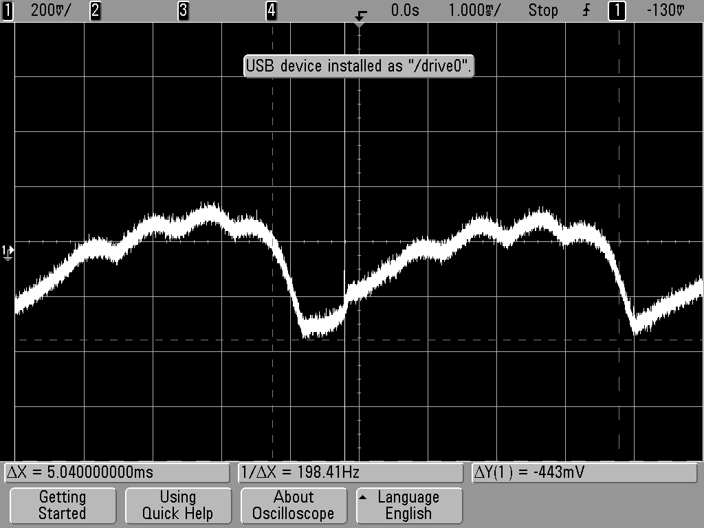
Then I decided to measure the ripple voltage right at the battery, which is shown below. The peak-to-peak ripple is smaller (about 400 mV) than at the radio but still present. I expected the the voltage to be mostly clean right at the battery.
I pondered what to do next. One approach would be to install a filter to eliminate the ripple. However, filtering out a few hundred Hz signal while maintaining a low voltage drop on the 12V power feed is not trivial. More importantly, I had the sense that the Escape’s electrical system was just not operating properly. I decided to take it to my local mechanic, who tested the alternator and determined that a diode had failed. He replaced the alternator for me and the whine is now gone.
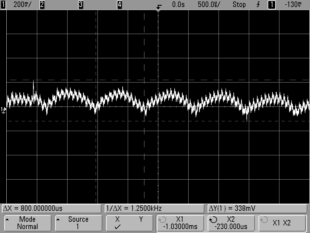
I did measure the 12 volt supply with the new alternator installed and the radio transmitting. I was surprised to find that there is still some ripple, a bit less than 200 mV (shown below). Apparently, this is not enough to disturb the FT-8900 signal.
So that’s the story about my alternator whine.
My spouse says “I still whine sometimes” but it has nothing to do with my ham transceiver.
– 73, Bob K0NR
Gremlins Lurk in the Junk Heap
Three weeks ago my EchoLink station went deaf. Thanks to the West Central MN Amateur Radio Club’s antenna analyzer, I figured out right away that the problem was in the feedline/antenna system. Ever since then I have been either too busy or too nervous to go on the roof, so it has remained a mystery . . . until this afternoon.

Antonio Mitchell checking SWR on the Edison Fong J-Pole
Antonio, my son, went up on the roof with the antenna analyzer while I watched from the ground. He did a great job taking all the tape and coax seal off the PL-259, disconnecting the coax from the antenna, and hooking up the antenna analyzer to the antenna with a patch cord. “One point two!” he called down to me. There you have it — it was the coax! I realized what I’d done. Here I had some brand-new coax in my field-kit, but I ended up grabbing a different coil of junk coax and got bitten by a Gremlin. I found the new, already-terminated coil of coax and Antonio swapped it for the bad length, carefully wrapping the PL-259 with coax seal and rescue-tape. In short order we had the station back on the air.
All that, and Antonio doesn’t even get to use it yet. Hopefully soon! Antonio has been studying hard for his Technician exam this week. He is eager to take the test.
Thanks, Antonio, for getting the EchoLink back up and running for all of us.

![]()
Now I understand – Measuring capacitance with a micro-controller
The excellent article by Rajendra Bhatt explains not only how capacitance can be measured but also how a micro-controller can be interfaced to an analog circuit to create a useful piece of test equipment.
 |
| Capacitance meter by Rajendra Bhatt |
I found the explanation of the RC time constant method of measurement as interesting as the micro-processor project itself and congratulate Raj on demonstrating a practical and workable real-life example of what can normally be a dry textbook subject.
Four State QRP Group hits a home run!
This sounds like a great kit at a fantastic price, for what you’ll be getting!
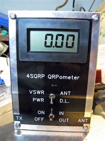
Dubbed the QRPometer during development, this useful accessory is a highly accurate and easy to use power and swr indicating meter. Unusual in any pwer meter, the range of accurate power measurement extends down to a low 100 milliwatts. It has a large digital display and boasts an accuracy level that few, if any, similar meters on the market can match. A unique design feature is that 2 circuit boards are included in the kit, they form the front and back of the enclosure. The boards are shiny black so there is no need to buy, build, or paint an enclosure.
This kit was conceived to fill a need within the hobby for an inexpensive, highly accurate VSWR and RF power meter for QRP power levels. The QRPometer uses simple analog signal-processing circuitry to provide a set of essential measurement features not previously available in a single unit. High quality, double sided, printed circuit board construction is used, with solder mask and silk screened component reference designators. All components are through-hole for easy assembly. NO toroids are required. All controls and jacks are PCB mounted, and a single, four conductor ribbon cable is the only wiring necessary. The QRPometer can be constructed by beginners as well as experienced builders. Construction time is approximately 3 hours, depending on experience level. The only equipment required for calibration of the QRPometer is a digital voltmeter, and a QRP transmitter.
First time builders please note: This kit is not difficult to build. All parts are thru hole parts, there are NO SMT parts. The parts are wide spaced on the board making installation easy, and all connectors are board mounted which eliminates point to point wiring. Also note that there are No TOROIDS to wind – none.
Specifications and Design Features
Power Range: 100 mW to 10 Watts
Accuracy: Power, 2% Typical
VSWR, 5% Typical
Large Digital Display The digits are .52″ in height.
Sensitivity: Direct readout on 3 1/2 digit LCD display. Minimum resolution 10 mW.
Enclosure: Silk Screened PC boards create the enclosure, no need to purchase one.
No Toroids: There are no toroids in this kit.
The price? Only $50.00 (US). Wow!
For all the details; and to order ……… http://www.wa0itp.com/qrpom.html
Please note that I am not a member of the 4 State QRP Group and have no “interest” in this kit, other than seeing great stuff get into the hands of my fellow QRPers!
72 de Larry W2LJ
EICO Model 625 Tube Tester
I attended the Greater Houston Hamfest and as I walked past the tables of equipment I wondered if interest in vacuum tube equipment was starting to wane. Compared to the last few years the prices of collector quality gear had held steady but parts and restorable gear seemed to be going for less. I’d like to know your thoughts if you’ve noticed trends one way or the other.
I was happy to pick up a EICO Model 625 tube tester for $15. It is in good condition and appears to work well. The roll of settings for each tube is in good condition and a little searching on the internet supplied settings for older tubes like the number 78 in the picture below.
 |
| EICO Model 625 Tube Tester with a number 78 tube |
The EICO 625 is not a top of the line tester but it does basic tests and will let you know if a tube is functioning and an idea of the life left in it. It was sold in kit form for $34.95 in 1958 which is roughly equivalent to $274 in 2012.
 |
| Inside the EICO 625 from diyaudioprojects.com |
The EICO 625 is fairly unique in having its own 6H6 diode tube to rectify the 30V filament voltage. It provides DC for the neon short-indicator bulb. If the tube is suspected of having a short then there is a fairly comprehensive series of tests than can be administered to isolate shorted elements.
 |
| EICO Model 625 circuit diagram |
Here is the complete TUBE TEST DATA 1/1/78 for the EICO Model 625 Tube Tester
Excellent information on servicing and calibrating your Classic emission tube tester.


