Posts Tagged ‘Test Equipment’
 Now I understand – Phase Locked Loops
Every now and then I come across great books or videos that explain a concept in such a way that it becomes immediately obvious what is going on. I’m a great believer in learning by demonstration or even better, learning by doing.
I came across another explanatory video recently that I thought was too good to keep to myself. It covers a topic that was a complete mystery to me: Phase Locked Loops. We utilize them in almost every modern transmitter and receiver yet most people I have talked to view them as a black box that, fortunately, does its job well and usually without interruption.
The video below does a good job on opening the black box and showing just what makes phase locked loops … well, lock.
Minimum-Loss Matching Pad
In my last post I promised to write about the minimum-loss matching pad that I’m using to couple my signal generator to the device I’m testing. The source impedance of the generator is 600 ohms and the output is intended to be terminated in a 600 ohm load, but the device I’m testing is only 228 ohms. The way to match this with the lowest loss is with a transformer, but it is inconvenient and unnecessary to come up with a transformer for every mismatch this piece of test-equipment will face.
Thanks to advice from the ham who is guiding me in this project, I’m using a minimum-loss matching pad, also known as an “L-pad,” to match these two impedances. (I’d tell you who this fine fellow is, but to keep you in suspense about my project I’ll wait until my final write-up. If I name him now, the cat will be out of the bag!) This quick, cheap, and easy match requires only two resistors:

Courtesy of http://www.microwaves101.com/encyclopedia/attenuatorL-pad.cfm#minloss
To calculate the value of the resistors and to calculate the loss of the matching pad, use these formulas (A spreadsheet that uses these formulas is available through this webpage.):

In my case R1=472, R2=290, and the loss is -9.25 dB. That loss is pretty significant, but it is acceptable for this application. Remember this is a minimum-loss matching pad, not a no-loss matching pad. Using what resistors I had on hand to come as close as I could to the required values, I soldered this pad on a generic PC board from Radio Shack that I cut in half using my Dremel tool with a cutting wheel:


For more on this topic, I commend to you this webpage on “Impedance and Impedance Matching.”


![]()
1Hz-2MHz Function Generator Kit
 After building the “Accurate LC Meter Kit” from Electronics-DIY.com, I turned to their “1Hz – 2MHz XR2206 Function Generator Kit”. All parts necessary to complete the kit were included, though not exactly as pictured on their webpage — two of the WIMA capacitors had been replaced with substitutes and there was no IC socket. All components were through-hole; soldering the kit together went quickly and easily.
If you build one of these kits you’ll need to provide your own power source as well as your own pin-connectors (if you choose to use the pins provided). As with the LC Meter, I used a size M coaxial DC power jack to accept a plug from one of the wall-wart power supplies I have around here. I didn’t bother to install a power switch in either unit since I won’t be using them very often; I won’t leave them plugged in between uses.
The fellow at the local Radio Shack gave me some pin-connectors for free, clipping them off of some battery packs that were in a box for recycling, though he only had two-pin connectors. Since one of the pin-sets has three pins, I just soldered a piece of hookup-wire to the third pin. If I had to do it all over again, I wouldn’t bother with these pins — I’d just solder hookup wire right to the PCB. By the way, if you ever try soldering to a pin make sure you clip a heat-sink to the pin before heating it up. The plastic base of those pins melts pretty quickly!
I chose a plastic project box from Radio Shack to house this function generator. Using a Dremel tool with an engraving cutter (at the lowest speed — 5,000 RPM), I put three notches in one side of the box for the potentiometers, a notch on one end for the two switches, and ground down all four stanchions on the floor of the box since otherwise the potentiometers would have extended too high to allow the lid to fit. That Dremel tool sure is handy! A few knobs from Radio Shack finished off the project.
The two outboard switches allow you to select between three waveforms — sine, triangle, and square. I don’t have an oscilloscope so I can’t tell you how the waveforms look, but I can at least tell you that the sine wave sounded pure when I hooked my headphones up to the output with a matching pad. I am pleased to report that the signal generated by this function generator is very stable. Four DIP switches on the PCB allow you to select between four frequency-ranges, and two potentiometers allow you to tune within the selected range. One of these two potentiometers provides coarse tuning, and the other provides fine tuning. The third potentiometer controls the amplitude of the signal generated (note: amplitude decreases as you turn this potentiometer clockwise).
If you build this kit you’ll want to hook it up to a frequency counter. Two pads on the PCB are provided for this purpose. I have a piece of coax hanging out of the back of the box for connection to my own frequency counter — not that you have to use coax, but it was handy for terminating with a BNC connector. (If I were really classy I would have put this coax through its own hole in the project box, but hey, this is a piece of test equipment — I just ran it through the big hole I made for the RCA connector.) When I hooked up my frequency counter I noticed that the published ranges for each DIP switch were just rough approximations, but I was pleased to see that this frequency generator covered the entire published range and more — up to about 2.4 MHz, if I recall correctly.
Here is a slideshow of photographs I took of the completed function generator:
The source impedance of the generator is 600 ohms and the output is intended to be terminated in a 600-ohm load. In my next post, I hope to discuss the construction of a minimum-loss matching pad to hook it up to a piece of equipment that has a different input impedance.


![]()
Accurate LC Meter Kit
Update (3/7/12): Yesterday I prompted [email protected] for a reply, mentioning the number of pageviews this post has received. I received a prompt and polite response. I learned that I was mistaken in expecting the meter to read capacitors 1 uF or higher, since the published range of the meter is only 0.1pF-900nF. There was no explanation of why I am having problems with inductors that are within the published range of the meter. However, I was quite favorably impressed by an offer to test and fix the kit at no extra charge! I shall take them up on this offer and keep you updated.
Update (2/8/12): I am having trouble with this LC Meter. It gives me the same reading for all capacitors 1 uF or higher, and the same reading for all inductors higher than about 70 mH (this last value is just a guess): 838.8 nF and 83.88 mH, respectively. As you can see the digits are the same. It seems to work for really small capacitors and inductors, but anything bigger and these are the only readings I get. I emailed [email protected] on 1/8/12 about this, but as of 2/8/12 I have received no reply. Unless and until I learn the problem is due to some error of my own in constructing this kit, I recommend against purchasing it.
 Yesterday evening I finished building the “Special Edition Accurate LC Meter Kit with Blue Backlight LCD”, available from Electronics-DIY.com for $69.95. I have no experience with such devices; a more experienced fellow told me he was impressed by its specifications, so I ordered the kit. Soldering it up was a snap. The main printed circuit-board is all through-hole construction, and the LCD-board that mounts over the top of it requires nothing but a connector.
If you want to build one of these you may want to order this version of the kit instead of the one I purchased: Accurate LC Meter Kit with Green Backlight LCD, for $59.95. My kit’s “Blue Backlight LCD” turned out to be green anyway, and I think the two kits have the same circuit, save an adjustable potentiometer on mine that controls the contrast of the LCD (which I just set to maximum anyway). Certainly the cheap case that comes with the kit I ordered is not worth the extra $10 — to use it you have to carve out a bunch of stuff (to make room for the circuit-boards), including two of the four stanchions that attach to the lid. After going to all that trouble (I used a Dremel tool) you are left with a case that requires adhesive tape to hold down one side of the lid!
The instructions that came with the kit were pretty sketchy, mostly limited to how you need to carve up the case (by the way, the measurements were wrong, so ignore them). The only thing that got me into trouble was the voltage regulator, which gets in the way of the LCD-board (and protrudes too high to seat the lid of the supplied case) if you solder it in the way you normally would (which I did!). By bending the voltage regulator out at angle I managed to get the LCD-board mounted, but the lid still won’t seat properly. Learn from my mistake, and bend the leads of the voltage regulator into a Z so that they lay flat on the board and allow the voltage regulator to sit just off the edge of the board. (Of course, this only matters if you try to use the case provided.)
You’ll need to supply your own power to this unit. There isn’t enough room in the case for a 9V battery, so I purchased a DC socket. You’ll also need to supply your own connectors for testing inductors and capacitors; the photograph on the Electronics-DIY.com website shows them in the case, but they aren’t supplied. I used banana-plug sockets. You’ll also need to supply your own pin-connectors if you use the supplied pins on the circuit-board, and you’ll need your own stand-offs if you want to support the LCD-board (only two of the four screw-holes match up with the lower PCB, but that’s probably good enough).
There is no way to select the units displayed on the screen, e.g. pF vs. nF. But the dearth of selector switches is actually one of the nice things about this unit. There is no need to select a range of capacitances or inductances. The only thing you have to do is plug it in, hit the reset button whenever you want to calibrate it, and stick in a capacitor to get a reading. If you want to test an inductor, you simply press one button to select inductance-mode, then attach your inductor. It just works — and it works with precision.
Here is a slideshow of some snapshots that I took with my cell-phone. They didn’t turn out very well, but they’re good enough to give you an idea of what it looks like. Notice that I used black electrical tape to mask the edges around the LCD. That’s because the opening I made was downright ugly. Next time I’ll try using a cutting wheel on my Dremel tool instead of a grinding tip!


Frequency check
In all the years I have been a ham and home constructor one item of test equipment I have never possessed is a frequency counter. Whenever I have needed to test if something is oscillating I have just stuck a bit of wire in the antenna socket of a receiver and listened for it, and if I have needed to tune an oscillator on frequency I have just tuned it for zero beat using a receiver that has been adjusted as best I could using WWV or similar.
Recently I decided that it would be useful to actually have a frequency counter, preferably a really accurate one. I know that it is possible to buy secondhand lab grade frequency counters on eBay. The trouble is that when your shack / workshop is the size of a broom cupboard there is no room for boat anchors. I didn’t even have space for one of the inexpensive desktop frequency counters that are available. I decided that I would have to make do with a hand-held device. Farnell had one, but the price of £140 was rather too steep given the amount of use it was likely to get. I was about to give up when I came across the Yaege FC-1 being sold for about £30 on eBay.
My initial thought was that this was such a cheap device that it could not be very accurate and was probably not worth getting. The specification gives the time base accuracy as < 5ppm, which is worse than most ham radio transceivers. However, a bit of searching produced a PDF copy of the manual, which revealed that the TCXO module is user adjustable. I figured that I could get better than the quoted accuracy by regularly calibrating it using my rubidium frequency standard.

I ordered one from one of the Hong Kong traders and it came in just over a week. The antenna socket is a male SMA, similar to that used on the Chinese VHF/UHF hand-held radios and the opposite type to that commonly used by Japanese manufacturers. A short UHF rubber duck antenna is supplied with the counter. I ordered a BNC adapter so I could use my BNC whip antennas and also attach BNC terminated test cables.
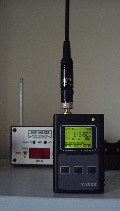
I connected it up to my 10MHz rubidium frequency standard and found that it was already within a couple of Hz of the correct reading. The picture was taken before I set the gate time to 1 second which is necessary to get a reading down to 1Hz.
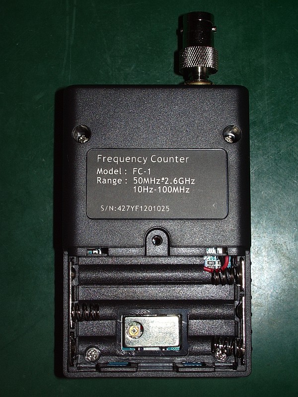 The time base oscillator adjustment is behind the battery compartment so you need to run the device from the charger while adjusting the frequency. You can see the adjuster in the picture on the right. Rather like adjusting the master oscillator in the Elecraft K2 the adjustment is incredibly touchy. The tiniest amount of movement can change the reading by a couple of Hz at 10MHz.
It turns out that it is not worth being so picky. The reading does slowly drift by a few Hz over a period of several minutes so you are never going to get absolute accuracy with a device like this. Nevertheless it is better than advertised and pretty good for the money, in my opinion.
One feature of the Yaege FC-1 that you don’t get with most frequency counters is a signal strength reading calibrated in dBm, as you can see in the top photo taken while I was transmitting a carrier on 145.500MHz. I wasn’t able to check how accurate the actual reading is but as a relative indicator the dB measurements seem quite accurate so this could be quite a useful tool for making antenna comparisons. It turns the frequency counter into a digital field strength meter.
Although it isn’t a lab grade high accuracy frequency counter I think the Yaege FC-1 is a useful addition to my electronic test equipment and is extremely good value for money.
Spot on
Having an interest in weak signal narrow band modes, not to mention APRS which requires you to park your receiver on a specific frequency, I have always wished that the frequency readout on my radios could be relied upon. The QRSS band, for example, is only 100Hz wide. If your dial reading is out by that much, you’ll miss it completely.
Many people try to calibrate their transceivers using WWV but that is not often a very good signal over here, and what with all the other carriers around 10MHz – many of them locally generated – you can never be sure that you have tuned to the right signal. I have wanted an accurate frequency reference for some time so a couple of weeks ago, following a comment by QRSS enthusiast Steve G0XAR, I ordered an Efratom LPRO-101 rubidium frequency standard on eBay. It arrived in about a week.
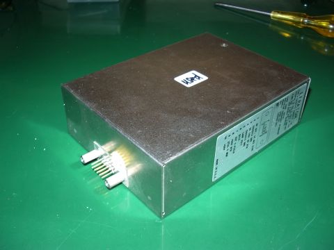
The unit I bought cost about £50 and came with a plug for the 10-pin connector and a 24V switched-mode power supply. These second hand units are widely available. New, they cost over $1,000 even in quantity. They are used in cellular base stations and are manufactured to have a maintenance-free life of ten years. To ensure reliable service the cellphone network providers take the equipment out of service before the ten years is up after which it is presumably shipped to China for reclamation. The used units should have several years of life in them, especially in occasional amateur use.
Rubidium frequency standards work by locking a crystal oscillator to the very precise frequency at which the amount of light from a rubidium lamp dips due to a phenomenon known as the hyperfine transition. A synthesizer locked to a reference oscillator is swept through this frequency until the dip is detected. The LPRO-101 includes an oven for the reference crystal, circuits to detect the dip and lock the oscillator, an output that tells you when the unit is locked, and the frequency reference output at 10MHz. The connector also provides signals that can tell you the state of health of the rubidium lamp. Once that fails you may as well scrap the unit because it can only be replaced by the manufacturer at a cost far in excess of what you paid for it.
To use the LPRO-101 you could simply attach a 24V supply and connect a cable to the 10MHz output. However, it’s useful to have a circuit that shows you when the unit is locked on frequency. I used one shown in an article by KA7OEI built up on a piece of Veroboard, which uses a dual-colour LED to light red when the reference oscillator is unlocked and green when it is locked. You can see the circuit board inside the partially assembled case.
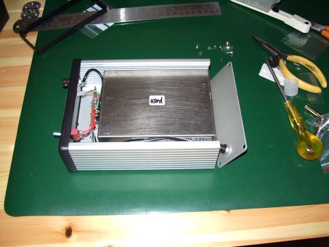
The voltage regulator and crystal oven inside the LPRO-101 generate a lot of heat so the unit is intended to be mounted on a heat sink. I purchased a Hammond extruded aluminium case to use for the project, which should provide reasonable heat sinking for the module.
One thing I learned from researching on the internet is that the LPRO-101 will run cooler when operated from its minimum recommended supply of 19V. This just so happens to be the output voltage of the power supply for an old Toshiba laptop whose screen failed so I decided to use that instead of the 24V supply that was sent by the seller.
The other thing I learned is that the rubidium lamps wear out with time. When they are made, the manufacturer ensures that they contain sufficient rubidium to achieve the stated maintenance free life of ten years, so the expected life in continuous use would be ten years less the use it has already had.
If I ran the unit all the time my rig is on – for example as an external frequency reference for a transceiver – then it is going to fail sooner or later. If I only use it for frequency calibration purposes, switching it on only when needed, then it will probably outlast me. The TCXO in my K3 is pretty stable so I should be able to obtain adequate accuracy for my purposes by manually calibrating the master oscillator using the rubidium standard and repeating this as often as necessary. How often that turns out to be, we’ll see.

Here is the finished unit. Annoyingly, I messed up the front panel of the rather expensive Hammond case. Originally I had intended to use an SMA socket for the output but I didn’t get the holes for its two mounting screws in the right place and after filing to fit it looked unsightly. So I fitted a BNC socket instead which is what I should have done in the first place. Unfortunately you can see the two holes for the SMA mounting screws either side of the BNC socket. So my frequency standard doesn’t look quite as professional as this one built by DL2MDQ. Oh well, it’s only a piece of test equipment!
Antenna analyzer from China
An antenna analyzer is a very useful piece of equipment and I have never regretted buying my AA-200, though I probably wouldn’t get one now with the current model priced at £410.00. Even the basic MFJ-259B which is not exactly renowned for its quality construction will set you back £260.00. So I was interested to discover that the Chinese have entered the market with the Feature Tech AW07A which can be bought on eBay for a much more reasonable £160.00.
 The unit can measure RF impedance and SWR from 1.8 to 490MHz (making it more directly comparable to the MFJ-269B model) as well as measuring capacitance and inductance. It may be used as a non-precision signal source and frequency counter, and with the addition of an inductor may be used as a dip meter. It looks like a nice addition to any amateur’s toolkit.


