 |
 Spot on
Having an interest in weak signal narrow band modes, not to mention APRS which requires you to park your receiver on a specific frequency, I have always wished that the frequency readout on my radios could be relied upon. The QRSS band, for example, is only 100Hz wide. If your dial reading is out by that much, you’ll miss it completely.
Many people try to calibrate their transceivers using WWV but that is not often a very good signal over here, and what with all the other carriers around 10MHz – many of them locally generated – you can never be sure that you have tuned to the right signal. I have wanted an accurate frequency reference for some time so a couple of weeks ago, following a comment by QRSS enthusiast Steve G0XAR, I ordered an Efratom LPRO-101 rubidium frequency standard on eBay. It arrived in about a week.
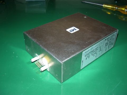
The unit I bought cost about £50 and came with a plug for the 10-pin connector and a 24V switched-mode power supply. These second hand units are widely available. New, they cost over $1,000 even in quantity. They are used in cellular base stations and are manufactured to have a maintenance-free life of ten years. To ensure reliable service the cellphone network providers take the equipment out of service before the ten years is up after which it is presumably shipped to China for reclamation. The used units should have several years of life in them, especially in occasional amateur use.
Rubidium frequency standards work by locking a crystal oscillator to the very precise frequency at which the amount of light from a rubidium lamp dips due to a phenomenon known as the hyperfine transition. A synthesizer locked to a reference oscillator is swept through this frequency until the dip is detected. The LPRO-101 includes an oven for the reference crystal, circuits to detect the dip and lock the oscillator, an output that tells you when the unit is locked, and the frequency reference output at 10MHz. The connector also provides signals that can tell you the state of health of the rubidium lamp. Once that fails you may as well scrap the unit because it can only be replaced by the manufacturer at a cost far in excess of what you paid for it.
To use the LPRO-101 you could simply attach a 24V supply and connect a cable to the 10MHz output. However, it’s useful to have a circuit that shows you when the unit is locked on frequency. I used one shown in an article by KA7OEI built up on a piece of Veroboard, which uses a dual-colour LED to light red when the reference oscillator is unlocked and green when it is locked. You can see the circuit board inside the partially assembled case.
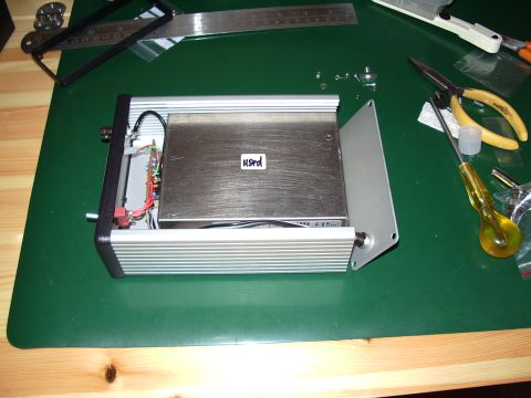
The voltage regulator and crystal oven inside the LPRO-101 generate a lot of heat so the unit is intended to be mounted on a heat sink. I purchased a Hammond extruded aluminium case to use for the project, which should provide reasonable heat sinking for the module.
One thing I learned from researching on the internet is that the LPRO-101 will run cooler when operated from its minimum recommended supply of 19V. This just so happens to be the output voltage of the power supply for an old Toshiba laptop whose screen failed so I decided to use that instead of the 24V supply that was sent by the seller.
The other thing I learned is that the rubidium lamps wear out with time. When they are made, the manufacturer ensures that they contain sufficient rubidium to achieve the stated maintenance free life of ten years, so the expected life in continuous use would be ten years less the use it has already had.
If I ran the unit all the time my rig is on – for example as an external frequency reference for a transceiver – then it is going to fail sooner or later. If I only use it for frequency calibration purposes, switching it on only when needed, then it will probably outlast me. The TCXO in my K3 is pretty stable so I should be able to obtain adequate accuracy for my purposes by manually calibrating the master oscillator using the rubidium standard and repeating this as often as necessary. How often that turns out to be, we’ll see.

Here is the finished unit. Annoyingly, I messed up the front panel of the rather expensive Hammond case. Originally I had intended to use an SMA socket for the output but I didn’t get the holes for its two mounting screws in the right place and after filing to fit it looked unsightly. So I fitted a BNC socket instead which is what I should have done in the first place. Unfortunately you can see the two holes for the SMA mounting screws either side of the BNC socket. So my frequency standard doesn’t look quite as professional as this one built by DL2MDQ. Oh well, it’s only a piece of test equipment!
One Response to “Spot on”
 Ham Radio Deluxe |
 W5SWL Electronics |
 Ham Radio Prep |
 KB3IFH QSL Cards  Hip Ham Shirts  HamRadioAuctions HamRadioAuctions Reliance Antennas Reliance Antennas Enigma Shop Enigma Shop |  morseDX  Ni4L Antennas  R&L Electronics R&L Electronics antennas.us antennas.us QRV QRV |
- Matt W1MST, Managing Editor

I made a nice face plate cover for a homemade unit like this:
1. injet printed a mirror of the face plate on a piece of overhead transparency film.
2. trim to fit the holes, painted the printed side with tan paint to match cabinet.
3. applied trimmed film to unit with spray adhesive.
Looks professional, covered my mistaken hole placement nicely. I’ll send a picture if you like.
de…Rynn