Archive for the ‘qrp’ Category
 Shut down two days in a row!
 July 20th, 2014 |
  Author:
  |
| A foggy view of Toronto from my setup |
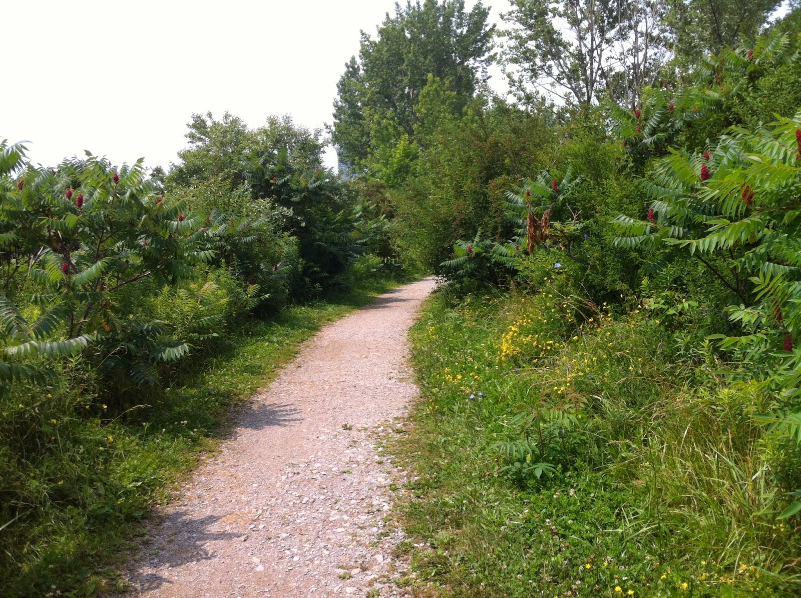 |
| Trail on the way there. |
 |
| Small river on my way home. |
 |
| One of the many beaches |
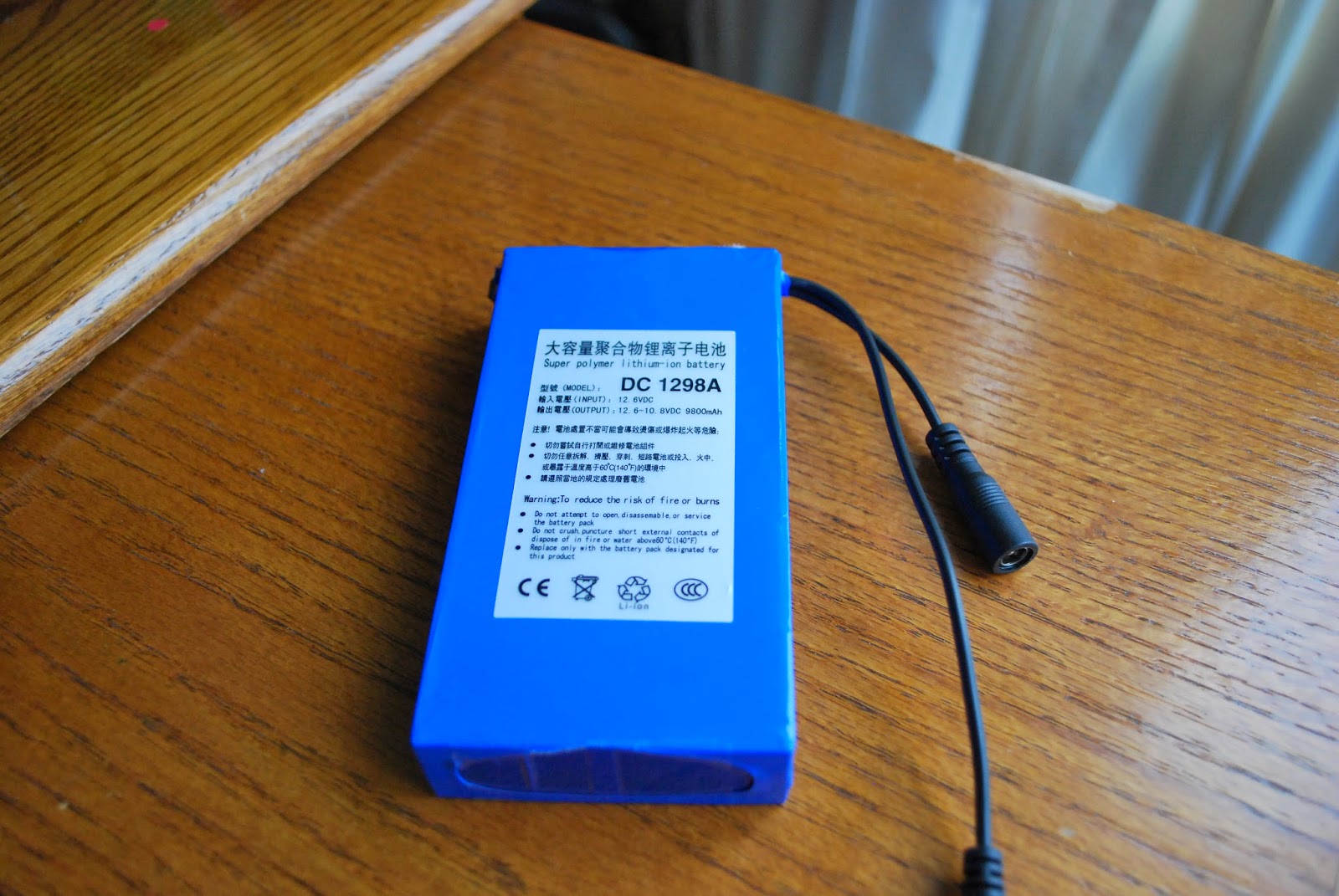
In the market for an external battery
China heard on JT-65? Call 3T4CAV?
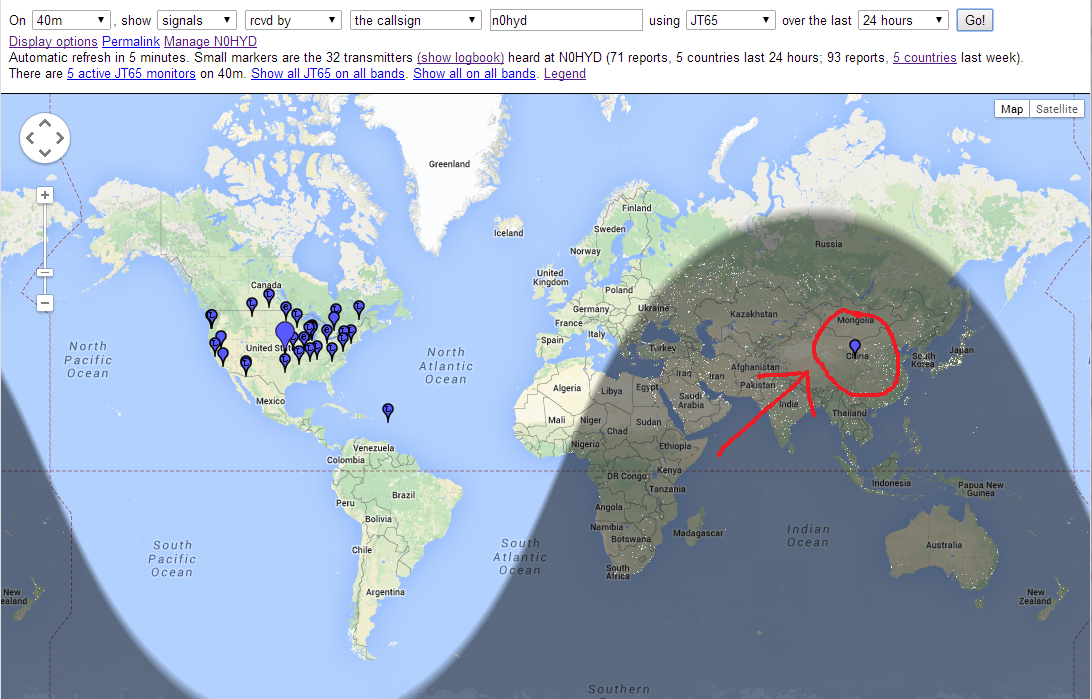 |
| Did I really hear China on 40M JT-65? |
Last night I played around some more with JT-65. The band conditions did not appear to be as good as they were the other night. I was on both 20m and 40m.
I worked a few stateside stations in the 40 minutes I played on the bands.
When I looked at PSK Reporter this morning I was greatly surprised to see one of the stations that I had spotted. It must have been one of the very first decodes I had after firing the rig up.
3T4CAV – in CHINA! I can’t find this call sign on any of the online databases, so I don’t know if this is a mistake in the database, I guess I doubt it is, but this is pretty amazing. And the signal report was -5db – which is actually a pretty strong signal report on JT-65.
I don’t remember seeing the decode on my screen, but I could have missed it as I was getting everything configured.
Anyway, that is pretty amazing if true.
Judging by the location of spots (both sent and received) around the country and down to South America, my 66′ ladder fed dipole in the attic seems to be working pretty well for this mode.
I do see lots of stateside stations working DX that I am unable to decode, so I think my initial feeling that receive is weak could still be true. But its not stopping me from having fun on this mode!
Space Weather, HF Radio Propagation – The Interview on ‘Ham Radio Now’
Why would an amateur radio operator be interested in space weather? Is it worth the time and resources to forecast propagation, in the daily operation of a typical ham radio station?
Gary, host of the popular ‘Ham Radio Now’ video podcast, talks with Tomas Hood (NW7US), propagation and space weather columnist for CQ Amateur Radio Magazine (and in the late ‘Popular Communications Magazine’ as well as ‘CQ VHF Quarterly Magazine’) and The Spectrum Monitor Magazine. Gary discusses with Tomas how scientists forecast space weather, and how the average ham radio operator can also make predictions, and what propagation forecasting can bring to the daily operations of an amateur radio enthusiast.
Watch on YouTube: ‘Ham Radio Now’ Episode 156: Propagation…

Tomas, NW7US, talks about radio propagation on shortwave (HF) as well as space weather.
Using the Ultimate3
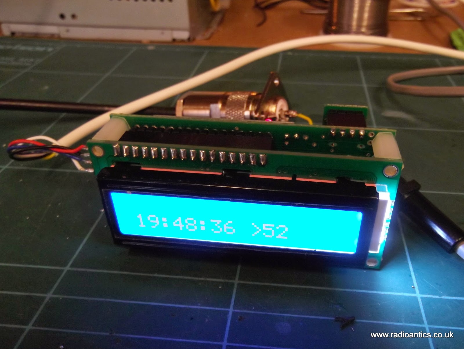
Until now it has been attached it to a dummy load with the FUNCube Dongle Pro+ SDR in close proximity as a receiver for experimental purposes.
One unresolved issue was it being consistently off frequency. The DDS modules used are prone to temperature fluctuations and component variances so the Ultimate 3 has the option of using a GPS module to provide both an accurate time source and an accurate 1PPS input which can be used to self calibrate. Except in my case it had proved to be unreliable.
I am using one of the inexpensive GY-GPS6MV2 modules containing the U-Blox chipset I posted about previously with the additional tap off to provide the 1PPS TTL signal.
Initially the GPS module was connected in close proximity to the Ultimate3 but struggled to maintain lock probably due to interference from the DDS module. Even when lock was achieved the calibration never seemed to work. I posted a question on the yahoo support group and from the answers I verified the calibration setting were correct so the only likely culprit was the quality of the 1PPS signal.
The serial NMEA sentences and the 1PPS signal from the GPS are likely to be required in other planned projects, such as an 'shack clock' and a GPS disciplined frequency standard. So I decided to put the GPS module into a waterproof housing that can fitted on the shack roof in clear view of the sky and away from any potential interference. A multi-cored cable supplies power and the TTL RX/1PPS signals being fed back to the bench.
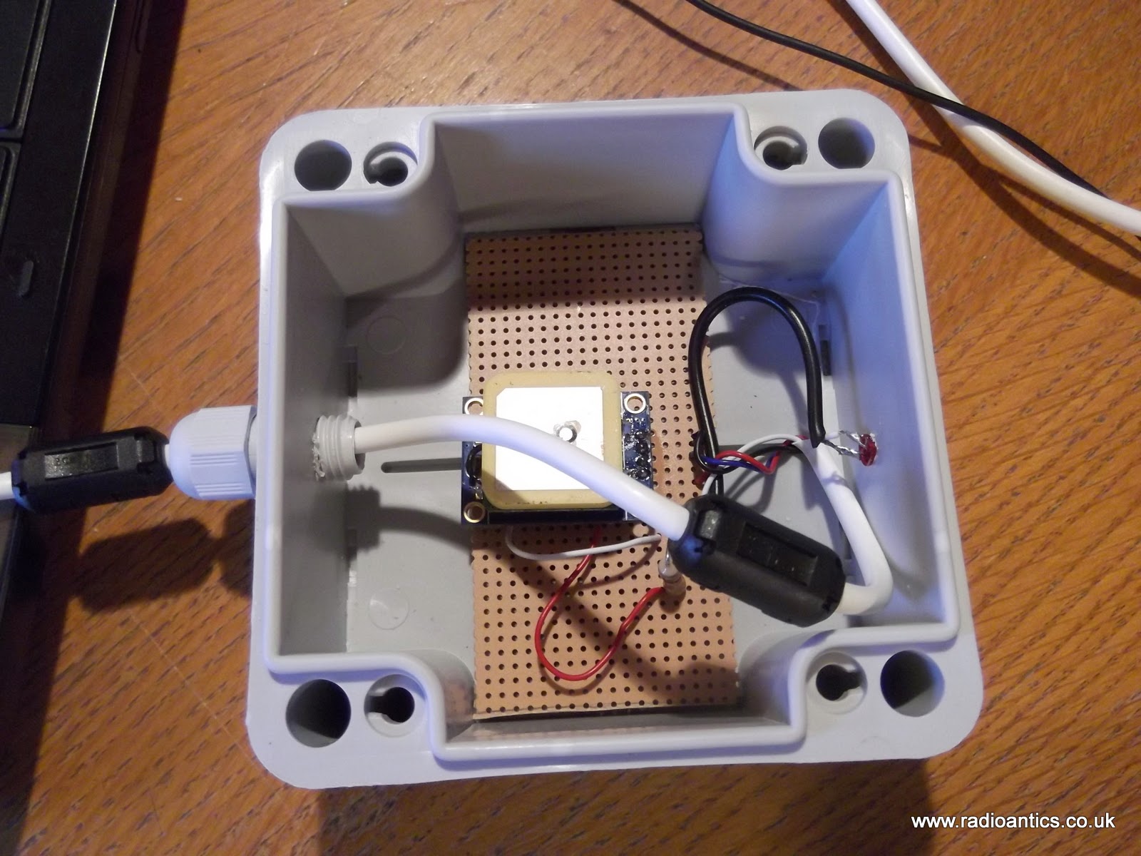
Sourcing an inexpensive weatherproof enclosure (£2) and waterproof cable gland were straightforward enough. I mounted the GPS module on a piece of strip board and replaced the on board LED with one mounted in the enclosure so I easily determine if the GPS had achieved lock, since it only flashes when it has. The LED is sealed with epoxy resin. It should be noted that the outputs of the U-BLOX chip are only rated at 10mA so bear it mind when selecting an LED and calculating the current limiting resistor. The connecting cable is some surplus unscreened alarm cable fitted with a couple of ferrite clamps.
The GPS now has no trouble achieving lock and quickly sets the Ultimate3 clock. Researching the 1PPS problem I hadn't come up with anything definite, as the signal looked okay on the oscilloscope. But I decided to fit a 10K resistor pull up resistor between the 1PPS output and the 3.3V supply on the GPS module. If this actually made the difference I have no idea but the Ulimate3 now successfully calibrates the DDS using the GPS.
At the moment I have configured the beacon to run WSPR and I have been spotted by other operators. Initially I wasn't getting much RF out of the device and it turned out to be a combination of poor connection caused by me not removing the enamel properly on a toroid winding and an iffy antenna connector. Both have been corrected and now get a measurable deflection on the SWR/Power meter. With the additional of a second power amplifier FET it is around 200-250mW.
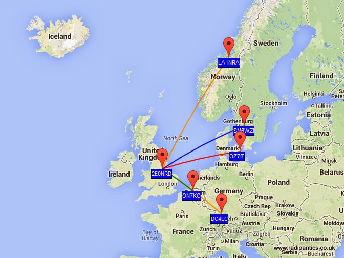
I purchased the Ultimate3 with a low pass filter for the 40M band and while I have had some European spots the results have been a little disappointing. 40M has turned out to be almost unusable at my QTH due to QRN/M so not sure if that is having an effect, also the antenna I have isn't naturally resonant on 40M so is going through a tuner which will certainly be introducing some losses, without the tuner the FETs get very warm!
With this in mind I have purchased some additional LPFs for the 30M and 20M bands and the LPF relay switching board for the Ultimate 3 so can try/run multiple bands.
Disappointment with Spice and the QRP-er’s favorite, the LM386
The trusty old LM386 audio amplifier from the 70’s is still used a lot in low power and portable equipment. Recently some ultra high gain circuits have been recommended that I wanted to simulate with Spice. I started with the datasheet examples for checking the quality of the model. The result was surprising.
In the data sheet one can find a minimum parts circuit, a high gain circuit, and a bass boost circuit:
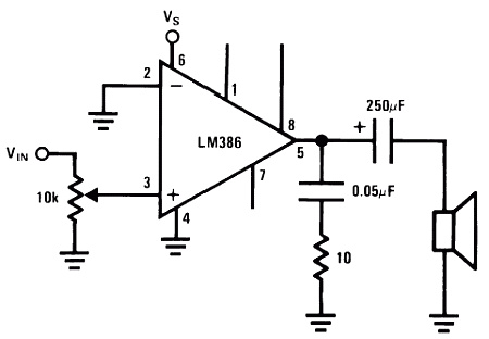 | 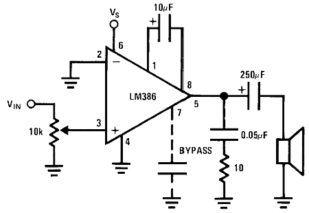 |  |
Gain = 20 (26 dB), minimum parts | Gain = 200 (46 dB) | Bass Boost |
There isn’t any official Spice model available from the manufacturer of the chip, at least not that I have been able to find. But there is a “no-frills LM386 model” attributed to Dave Dilatush (5/30/95) so I used that and a put it in a separate LM386.sub file.
The Spice code is quite simple and listed at the end of this posting. The result is shown here in two sets of curves. The first is for the 26 dB and 46 dB amplifiers.
The first result is in the left-hand curve which shows that the high-gain version has problems with the low frequency response, so I increased the 10 μF feedback capacitor to 100 μF in the right-hand plot (between pins 1 and 8). That makes the plot almost as flat as that of the data sheet down to 100 Hz.
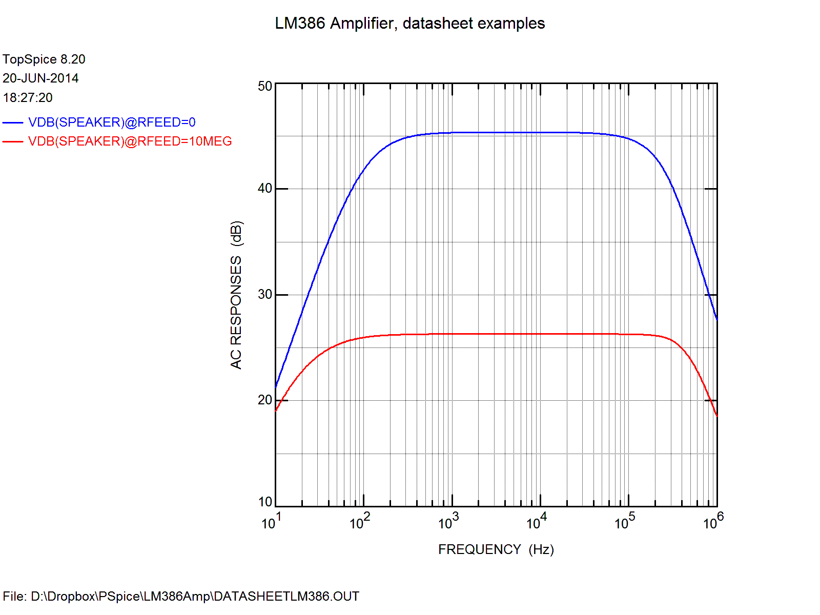 |  |
| 26 and 46 dB amplifiers according to data sheet | 26 and 46 dB amplifiers with 100 uF in the feedback |
Second, the high frequency response is too high in the simulation compared to the data sheet shown below. The Spice model does not seem to have enough high-frequency roll-off.
Third, close inspection shows that the gain of the high-gain amplifier (the blue curve) levels off at 45.4 dB, not 46 dB. This should indicate that the open-loop gain of the Spice model is not high enough.
For comparison, the data sheet plots the responses as follows:
 | 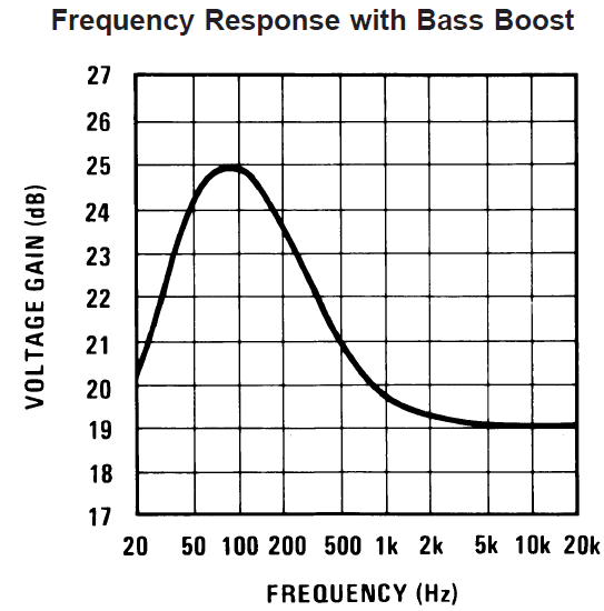 |

Finally here is the simulation of the bass boost. It is actually quite close to that of the data sheet, probably because the gain is not very high and the original plot only goes to 20 kHz.
In conclusion, in order to do simulate the LM386, there is a need for a Spice model with more roll-off at high frequencies and with a higher open loop gain.
I also observe that there is a constant current source in the LM386 model of value i1=5 mA. It must for sure be too high since the data sheet says that the quiescent current for the entire chip is min. 4 mA, max 8 mA.
Before there is any point in simulating the “Unleashing the LM386“-circuit that I introduced in Sprat (autumn 2003) or the simplified version that SM7UCZ (Johnny Apell) introduced in Sprat this spring – both based on the circuit of JF1OZL (Kazuhiro Sunamura), the Spice model needs some improvement. These circuits are also in George Dobbs, G3RJV’s articles in Practical Wireless, May and July 2014.
Actually I knew that improvements are needed since I have already tried with inconsistent results. But I have the hope that some of the readers may steer me towards an improved model.
Links:
- Dave Dilatush no-frills LM386 model.
- Comments on the quality of the LM386 Spice model.
- Datasheet for LM386
Spice code for use with TopSpice or LTSpice:
LM386 Amplifier
*
*
* LM386 Data Sheet curves simulated in TopSpice
* Sverre Holm (LA3ZA), 20 June 2014
*
**********************************
.include lm386.sub

* Step through 26, 34, 46 dB
cfeed nc4 100 10uF
*rfeed nc3 100 {Rvar};     LTSPice
*.STEP param Rvar LIST 0.01 10Meg;          LTSpice

rfeed nc3 100 10Meg;     TopSPice
.STEP Rfeed LIST 0 10Meg;    TopSpice

* Comment out for flat response (default)
*Xfeed nc3 output BassBoost

.probe
.ac dec 100 10 1e6 ; 100 steps per decade from 10 Hz to 1 MHz
*.tran 1u 3m 0 5u
.save vdB(speaker)
*.print ac V(speaker);  LTSpice
.print ac vdB(speaker); TopSPice

vsupply vcc 0 dc 9
rsupply vcc vs 10
csupply vs 0 470uF

vsignal inn 0 ac 1 sin 0 .05 1k
rplus nc1 0 1e-6

* Output circuitry
csnub output snub .05uf
rsnub snub 0 10
ccoupling output speaker 250uf
rspeaker speaker 0 32

xamp inn nc1 nc2 nc3 nc4 output vs 0 lm386

cbypass nc2 0 0.1uf ;bypass cap for PSRR

************************************************************
* Bass boost (in LM386 Data Sheet)
.subckt BassBoost nc3 output
cfeed output 10 33nF
rfeed nc3 10 10k
.ends BassBoost
************************************************************
.end
Spice circuit for the LM386 (store in LM386.sub):
* NO-FRILLS LM386 MODEL
* Dave Dilatush 5/30/95
*
*http://groups.google.com/group/sci.electronics/browse_thread/thread/4acbf7a7f3c36b0f/db8514b79b5b1709
*

* lm386 subcircuit model follows:

* IC pins:     2   3   7   1   8   5   6   4
*              |   |   |   |   |   |   |   |
.subckt lm386 inn inp byp  g1  g8 out  vs gnd

* input emitter-follower buffers:

q1 gnd inn 10011 ddpnp
r1 inn gnd 50k
q2 gnd inp 10012 ddpnp
r2 inp gnd 50k

* differential input stage, gain-setting
* resistors, and internal feedback resistor:

q3 10013 10011 10008 ddpnp
q4 10014 10012 g1 ddpnp
r3 vs byp 15k
r4 byp 10008 15k
r5 10008 g8 150
r6 g8 g1 1.35k
r7 g1 out 15k

* input stage current mirror:

q5 10013 10013 gnd ddnpn
q6 10014 10013 gnd ddnpn

* voltage gain stage & rolloff cap:

q7 10017 10014 gnd ddnpn ;
c1 10014 10017 15pf

* current mirror source for gain stage:

i1 10002 vs dc 5m
q8 10004 10002 vs ddpnp
q9 10002 10002 vs ddpnp ; diode

* Sziklai-connected push-pull output stage:

q10 10018 10017 out ddpnp
q11 10004 10004 10009 ddnpn 100 ; diode D1
q12 10009 10009 10017 ddnpn 100 ; diode D2
q13 vs 10004 out ddnpn 100
q14 out 10018 gnd ddnpn 100

* generic transistor models generated
* with MicroSim's PARTs utility, using
* default parameters except Bf:

.model ddnpn NPN(Is=10f Xti=3 Eg=1.11 Vaf=100
+ Bf=400 Ise=0 Ne=1.5 Ikf=0 Nk=.5 Xtb=1.5 Var=100
+ Br=1 Isc=0 Nc=2 Ikr=0 Rc=0 Cjc=0p Mjc=.3333 ;
+ Vjc=.75 Fc=.5 Cje=5p Mje=.3333 Vje=.75 Tr=10n ;
+ Tf=1n Itf=1 Xtf=0 Vtf=10) ;

.model ddpnp PNP(Is=10f Xti=3 Eg=1.11 Vaf=100
+ Bf=200 Ise=0 Ne=1.5 Ikf=0 Nk=.5 Xtb=1.5 Var=100
+ Br=1 Isc=0 Nc=2 Ikr=0 Rc=0 Cjc=0p Mjc=.3333 ;
+ Vjc=.75 Fc=.5 Cje=5p Mje=.3333 Vje=.75 Tr=10n ;
+ Tf=1n Itf=1 Xtf=0 Vtf=10) ;
.ends
*----------end of subcircuit model-----------
CWT Mini-Contest – QRP Style
 In my continuing effort to evaluate my attic dipole, several guys have given me advice to get on during a contest because the activity level is higher on the bands and I could better evaluate what I can hear.
Every Wednesday (local) evening from 0300-0400Z (Thursday) the CW Operators Club has a mini-contest the call CWT. The exchange is name and member number or name and state if a non-member.
These guys are serious CW operators, and I knew the pace would be fast. I downloaded N1MM for logging as they have a dedicated module for the contest. They also have a call history file that you can load which allows you to enter the call and it matches the name and member number up for you.
So I had everything setup and ready. I started on 20 meters and heard some activity. I made one contact there before heading to 40 meters.
On 40 meters the band was filled with signals – this warmed my heart after my recent worries with my antenna!
CW was being sent very fast – but after several listens I could usually get the call. I just looked at the scores here http://3830scores.com/currecscores.php?arg=JxfqcDz6ficvT – I ended up last in the QRP category, but NOT last in the contest!
I ended the night with 6 QSO’s during the hour long contest. Honestly, I am happy with those results. My goal was 10 contacts, but I learned some valuable lessons which will help me next time!
Here is the list of my contacts (all CW Ops Members):
K1BG Bruce 20M – MA
N1LN Bruce 40M – NC
KC4D Bill 40M – VA
N5ZO Marko 40M – CA
AD4EB Jim 40M – TN
N5AW Marv 40M – TX
So I worked 6 different states – MA, NC, VA, CA, TN, TX – coast to coast!
Thanks to those that pulled my QRP signal out! I will be back to this contest in the future!