Author Archive
 Book rather than Blog
My blog has suffered in recent years and here is the reason. For three years now I have been writing a book entitled “Waves with Power-Law Attenuation”. It is now in Springer’s catalogue under classical continuum physics and I’m also very happy that it is published in the Acoustical Society of America Press series.
The emphasis is on models for waves that experience attenuation that follows a power-law in frequency. Topic-wise it is more about mechanical than electromagnetic waves, but analogies are drawn between the two fields as many of the models are the same. Power-law models in electromagnetics are in particular useful for waves in biological tissue, which is indeed also the case for acoustic and elastic waves.
The description starts like this:
“This book integrates concepts from physical acoustics with those from linear viscoelasticity and fractional linear viscoelasticity. Compressional waves and shear waves in applications such as medical ultrasound, elastography, and sediment acoustics often follow power law attenuation and dispersion laws that cannot be described with classical viscous and relaxation models. This is accompanied by temporal power laws rather than the temporal exponential responses of classical models.“
Read more on Springer’s site.
Power regulator works as polarity protection
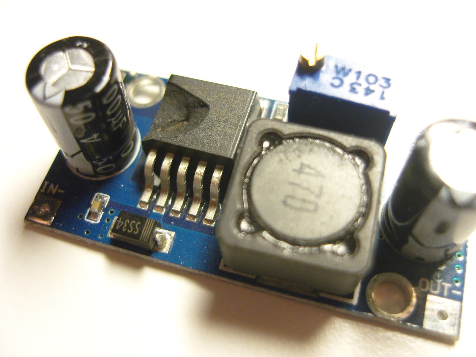 |
| Step-down converter based on LM2596. Note the damaged chip |
Ok, now I’ve done the test. My QRPLabs U3S runs off a 12 Volt power supply. There are two step-down converters, one for 5 Volts for the processor and another adjustable one for the power amplifier, if one can call 0.2-0.5 Watts a power amplifier. See picture of these voltage converters in this post.
I happened to make a new cable for 12 Volts which had the polarities inverted – and puff – there was a noise and absolutely no response from the U3S. I feared that I had blown the entire circuit. As my power amplifier was turned off, only the 5 Volts supply was affected and upon inspection I found that the voltage converter had a destroyed chip.
Since since they are so cheap, I had a spare. Luckily for me, the U3S worked as it should after replacement. So the LM2596 can take a reversed polarity and sacrifices itself in order to protect the rest of the electronics. Nice!
This post first appeared on the LA3ZA Radio & Electronics blog.
Deteriorating ceramic filters due to DC
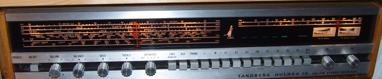 |
| Tandberg Huldra 10 |
Tasos, SV8YM, has written about “The Mysterious Case of the Withering Filters“. This seems to affect not only ham radio transceivers, but FM stereo receivers as well.
Tandberg from the 70’s are collectors items and since I actually worked one summer at Tandberg in the early 70’s they bring back good memories for me. The latest generation of receivers (2nd version of Huldra 10, Huldra 11, and Huldra 12) had ceramic filters for the 10.7 MHz intermediate frequency for FM. It is also known that these filters deteriorate leading to reduced sensitivity over time.
SV8YM has pointed out that ceramic filters deteriorate due to DC on the terminals, especially the output terminal and that this leads to electromigration. In the Huldra 10, both filters have 7.1 V DC on the input. Filter F1 has 0 V DC on the output, while F2 has 2.1 V on the output.
 |
| Old filters (left) and new filters |
As I got ready to replace mine with new Murata filters (SFELF10M7GA00-B0, 230 kHz bandwidth), I read the same warning in their specifications, which says: “For safety purposes, connect the output of filters to the IF amplifier through a D.C. blocking capacitor. Avoid applying a direct current to the output of ceramic filters.“
I also noticed that the filters had been replaced before. To be sure, I added three coupling capacitors (10 nF – 0.01 uF). This value has a reactance of 1/(2 pi 10.7e6 0.01 e-6) = 1.5 ohms which is negligible compared to the 330 ohm termination impedance. They were surface mount capacitors which is quite some upgrade as they perhaps were not even invented when this receiver was designed. They were fitted under the PCB by cutting the appropriate trace. Whether this has any long-term effect I don’t know, as the Huldra 10 at the age of 40 years is beyond its design life anyway.
My somewhat inaccurate oscilloscope measurements indicated that the passband attenuation in F1 was reduced from 7 to 4 dB and in F2 from 9 to 2 dB, in total maybe as much as 10 dB gain. FM sensitivity seems to have been restored to normal value after this replacement, so it was well worth the effort.
 |
| The three new 10 nF coupling capacitors, circled in red |
 |
| The two filters, circled in red |
QRSS experiments: FSKCW and Slow Hell
These last few days I’ve been experimenting with my QRPLabs Ultimate 2 and Ultimate 3s transmitting on 7 MHz. In addition to WSPR, the modes transmitted have been FSKCW with 6 second long dots, and Slow Hell with 17 second long characters. The result as received this morning can be seen on the display from the grabber of Les, G3VYZ in Northumberland, UK. This is a stack of 6 consecutive 10 second frames as can be found on the QRSS grabber site of AJ4VD.
 |
| FSKCW and Slow Hell reception of LA3ZA at G3VYZ |
My signal is on 7,039.870 kHz and has been set up with a FSK shift of 6 Hz. Power output was 0.2 W and the distance is about 890 km.
It works but the reception is much less reliable than for WSPR, which is not so unexpected. At the same time the WSPR signal was received all around Northern Europe (G, GM, DL, OON, OE, LX, LA, OY, OH, PA, SM) as well as on the Canary Islands, 3930 km away.
FT8 anomaly or long delayed echo?
My friend Alf, LA2NTA, has sent med these screenshots from when he has been operating FT8. The first image is when operating 10 meters and took place early in November.
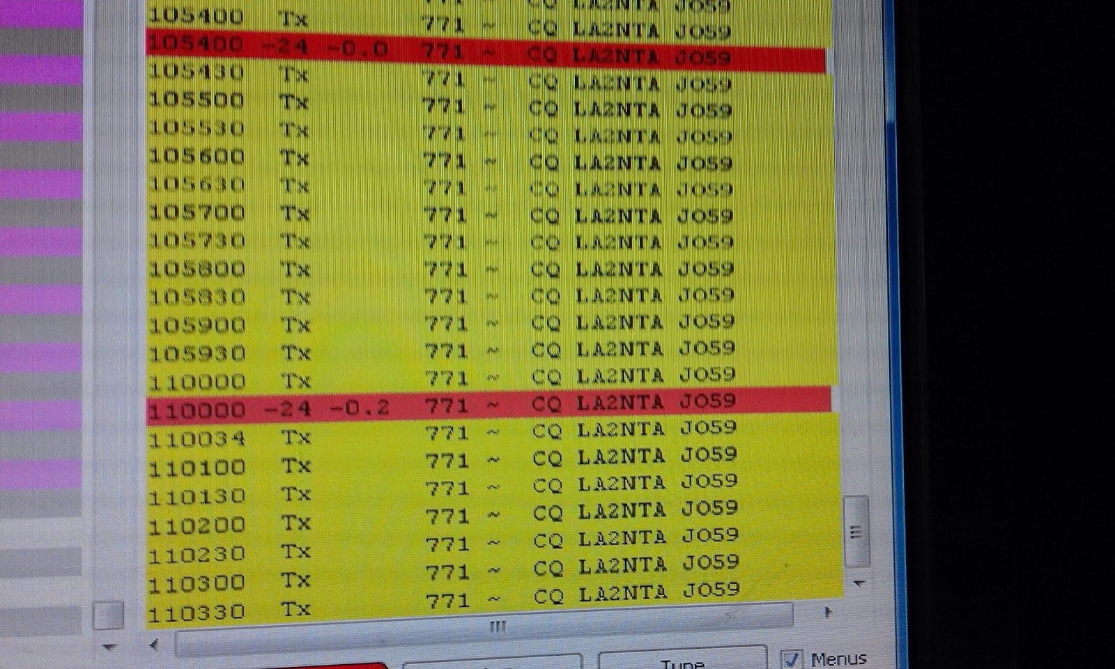 |
| Two of LA2NTA CQs being received by himself on 10 meter (in red) |
It shows how his own CQ comes back to him at 10.54.00 and at 11.00.00 and is decoded in his own receiver.
The second example is from 20 meters and took place just a few days ago.
 |
| LA2NTA CQ being received by himself on 20 meter (in red) |
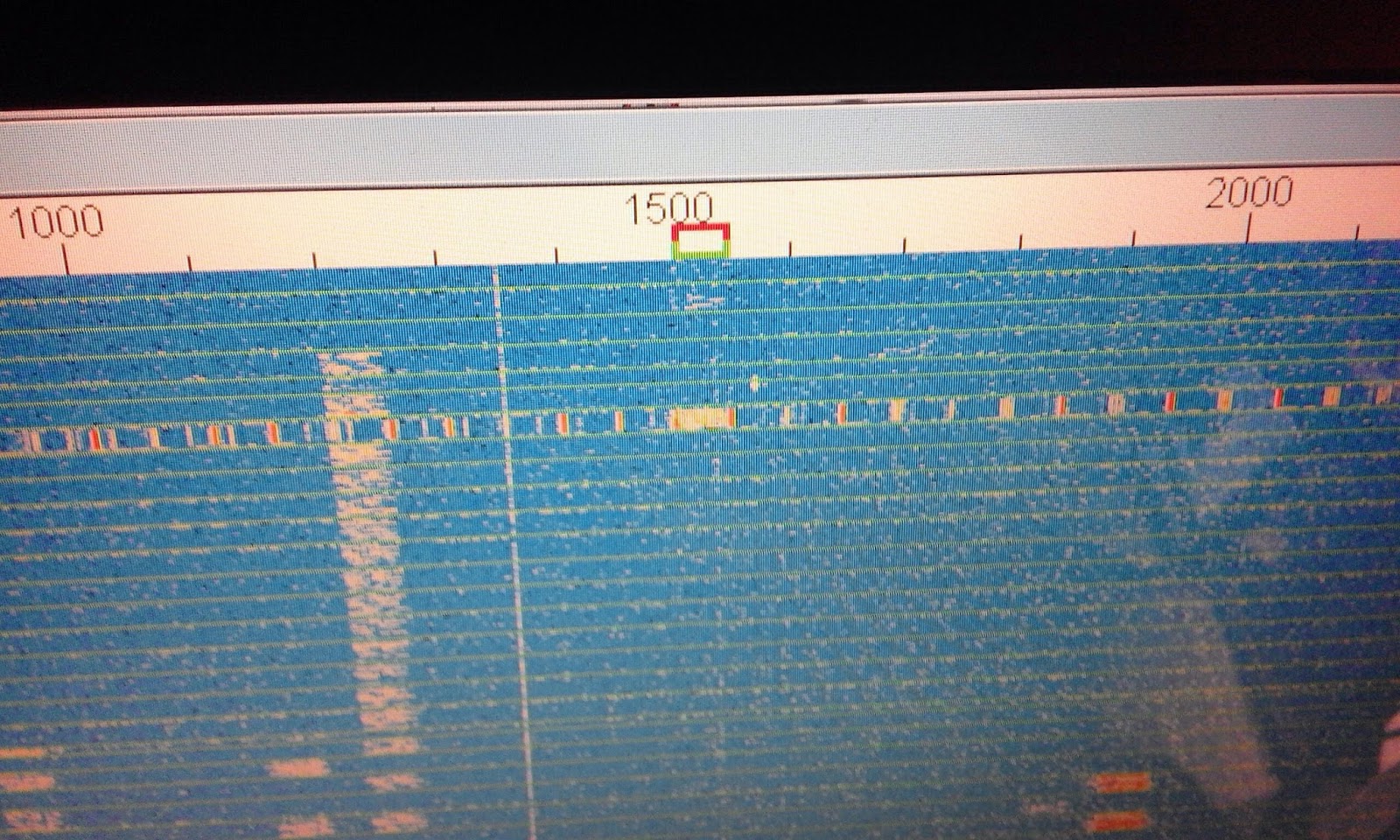 |
| FT8 band on 10 meters showing some form of noise all over the band |
Simple interference fix for the Chinese Pixie
The Chinese Pixie transceiver operating at 7023 kHz has become very popular. It often costs less than 5 USD on Ebay. Like most Pixies it is susceptible to broadcast breakthrough and intermodulation. Much of this is caused by the keying circuit of the audio amplifier, the LM386. The cure is to move the muting diode from the power supply pin (no. 6) to the bypass pin (no. 7). I have described this in another blog post with title: “Using pin 7 of the LM386 to reduce BCI and add side tone to Pixie 2“.
Here are two pictures that show how this can be done for the Chinese Pixie. One needs an additional resistor in the range 10 – 47 ohms. I have used 10 ohms in the picture. It replaces the old R3 of 1 k. The diode D3 is not mounted, and instead it is mounted under the PCB with the minus (denoted by the ring) connected to where D3’s minus was, and the plus side connected to pin 7 of the LM386.
 |
| R3 is indicated by the lower left arrow, and the old placement of D3 is shown with the upper arrow |
 |
| Arrow showing where D3 instead should be soldered. The minus, indicated by the ring, is to the left in the image |
Simple interference fix for the Chinese Pixie
The Chinese Pixie transceiver operating at 7023 kHz has become very popular. It often costs less than 5 USD on Ebay. Like most Pixies it is susceptible to broadcast breakthrough and intermodulation. Much of this is caused by the keying circuit of the audio amplifier, the LM386. The cure is to move the muting diode from the power supply pin (no. 6) to the bypass pin (no. 7). I have described this in another blog post with title: “Using pin 7 of the LM386 to reduce BCI and add side tone to Pixie 2“.
Here are two pictures that show how this can be done for the Chinese Pixie. One needs an additional resistor in the range 10 – 51 ohms. If you can fit it, then use the large 51 ohms resistor that come with some of the kits (I think it is meant for a dummy load). I have used 10 ohms in the picture. It replaces the old R3 of 1 k. The diode D3 is not mounted in the holes provided, and instead it is mounted under the PCB with the minus (denoted by the ring) connected to where D3’s minus was, and the plus side connected to pin 7 of the LM386.
|
| R3 is indicated by the lower left arrow, and the old placement of D3 is shown with the upper arrow |
|
| Arrow showing where D3 instead should be soldered. The minus, indicated by the ring, is to the left in the image |
The post “Simple interference fix for the Chinese Pixie” first appeared on the “LA3ZA Radio & Electronics Blog.”


