Author Archive
 Altoids Projects
 |
| Press image for magnification |
I like to build small electronics projects and like many others I have found the small Altoids tins to be excellent enclosures.
These tins are inexpensive, well shielded, easy to work with, and least but not least they enable you to make experimental circuits that are sturdy enough that they can be reused later.
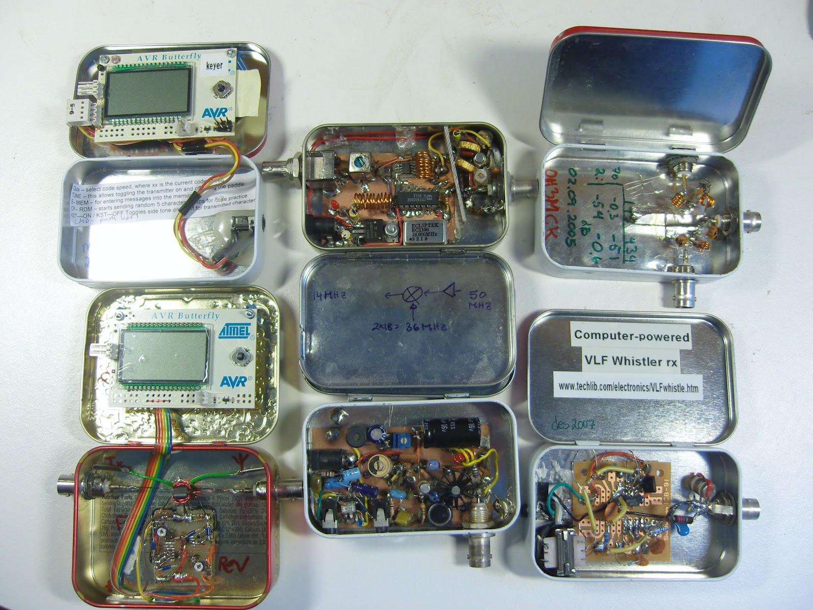
Pictured here is a collection of projects I have built over the years with the hope that they may inspire others.
To the left:
- AVR Butterfly morse keyer (KD1JV)
- AVR Butterfly Digital SWR / Power Meter for low power transmitters (KD1JV). Actually this project was built in the slightly larger Whitman’s tin.
In the middle:
- 50 MHz to 14 MHz receive converter (WA3ENK) with a low-noise preamplifier
- Pixie II QRPP transceiver for 30 m
To the right:
 |
| Press image for magnification |
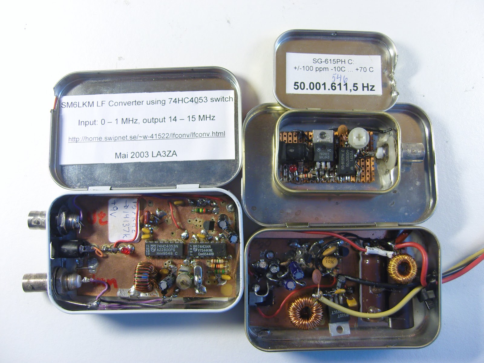
In the next picture there are some more projects:
- SM6LKM’s 4053 HCMOS converter from 137 kHz to 20 meter band.
- A 50 MHz test oscillator for testing 6 m receivers
- A switch mode power supply that converts 15 Volts into 4.5 and 30 Volts for a WWII miniature Sweetheartshortwave receiver. Design inspired by SM0VPO/G4VVJ’s practical voltage converter.
Here are some resources with tips:
- Maxim Tutorial 946: Disposable Metal Boxes Make Excellent Shielded Enclosures (via Dangerous Prototypes)
- Getting Started – Top 10 Small and Fun Electronics Projects – DIY Electronics
- Curiously Hackable: 8 Awesome Altoids Tin Hacks
- Altoids tin prototyping board (Make blog)
Added 17. September: Several of the comments on the page at Dangerous Prototypes are concerned with the difficulty of finding Altoids tins in many places of the world. That goes for Norway also. I have been lucky enough to have a job that allows me to travel to the US from time to time and then I have bought some. Ideas for local alternatives are needed!
Noisy Designer Lamp
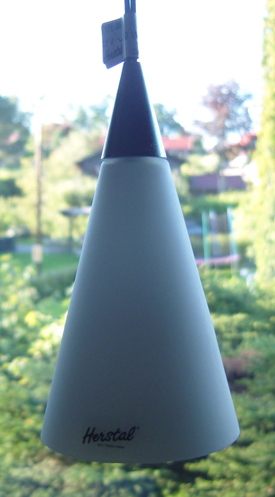 |
| Herstal pendant lamp, type 06 |
Some years ago I had this annoying noise that made listening for weak signals on several of the shortwave radio bands virtually impossible. In the end I was finally able to track down the noise source: Our beautiful Danish Herstal designer lamps in the kitchen. Actually it wasn’t the lamps themselves, but the dimmable switch mode power supply that came with them.
After some years of always having to remember to turn them off, in the end I just replaced the original noisy dimmer with a fixed voltage, noiseless, electronic transformer and inserted lower wattage 12 V light bulbs in the two lamps.
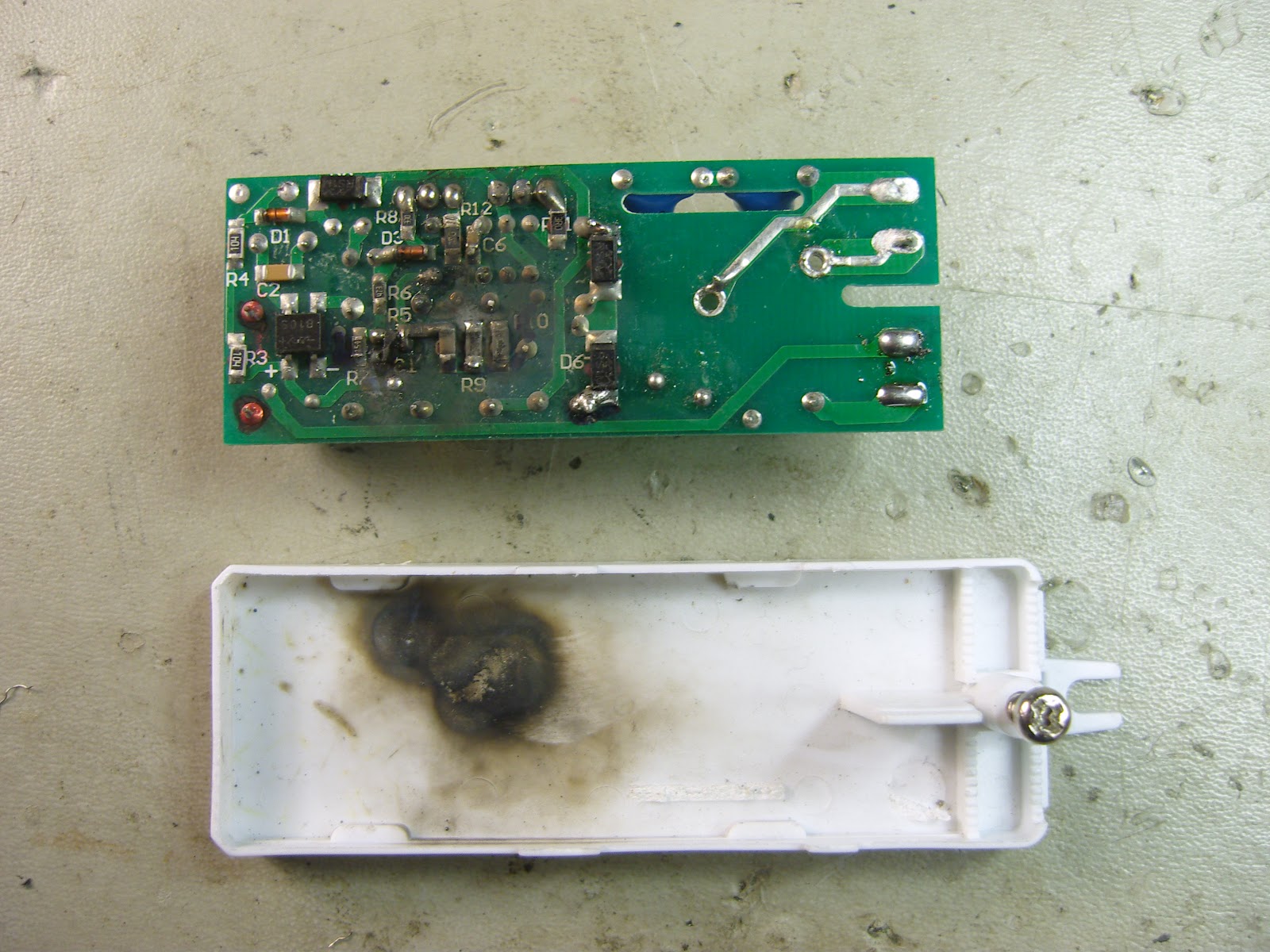
The original dimmer came in its own nice conical designer housing and inside one finds a more ordinary plastic housing. And of course it is marked with the CE mark, thus indicating that it should be fine with respect to noise. But as I kept opening it up, I finally found the printed circuit board. Interestingly, there are several components which have just been bypassed with wires. The most important one must be the one to the left of the center hole. Here two wires have replaced a component connected more or less directly to the 230 V AC input.
I believe this is a common mode filter. These filters hardly serve any purpose when it comes to the function of the dimmer. But they are vital for ensuring that the dimmer does not radiate noise on the power line, and probably also for achieving the CE mark.
 |
| Press for larger image |
I think the manufacturer, Herstal, may have cut some corners here in order to save cost. They seem to have fallen for the temptation to remove this filter component after it initially had been designed in.
Who at Herstal who made that decision, I can only speculate about. But since the filter initially was there, I think that it was someone other than the design engineers.
Fixing my Lithuanian oscilloscope

I visited Riga, Latvia with a youth group which we as a family were involved with in 1992, and there I stumbled upon a Soviet oscilloscope in a department store. It was from the neighboring country, Lithuania, and was manufactured in Vilnius, the capital. The markings say what I guess means “Made in the Soviet Union”. At least it says CCCP in the upper right-hand corner. I remember these letters very well as all Soviet athletes used to have them on their backs.
The oscilloscope came with full documentation, even with a bilingual manual. I had grown fond of this oscilloscope as it was lightweight and simple to use once I had learned what the Russian markings meant. It is a typical instrument for TV-repair with a 7 MHz bandwidth.
Now after 20 years, I was therefore very sad when it malfunctioned. This was the time to test if the manual was helpful or not. The symptom was that the beam no longer could span the whole screen in the X-direction. Even with the Horizontal positioning all the way to the left one could barely see the beam.
I opened the bilingual manual only to discover that the two languages were Russian and Lithuanian!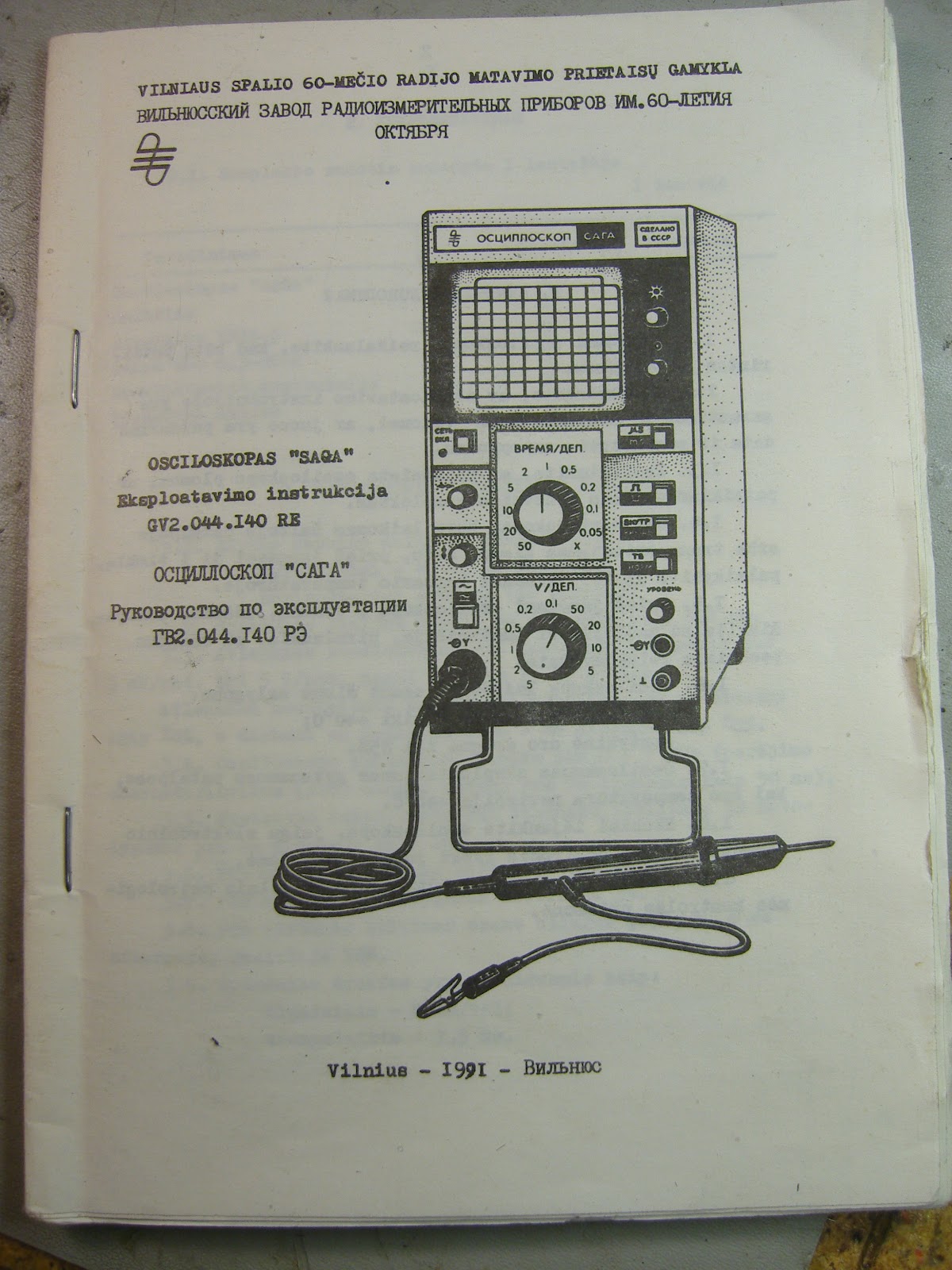 But lucky for me, the schematic was similar to what I am used to and quite readable. It even contained PCB-layouts.
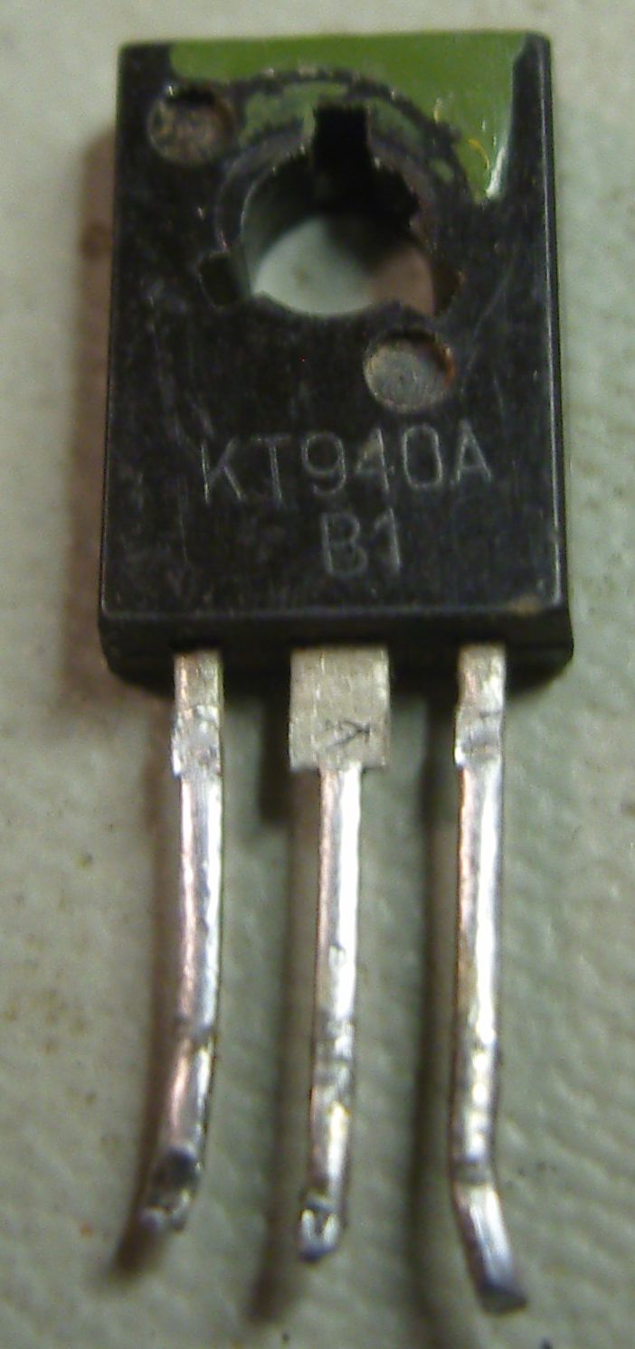 It showed two high-voltage transistors, KT940A, in the last stage of the horizontal amplifier. One of them turned out to have an open emitter-base junction. Specs that I could decipher from Russian data sheets on the web showed that KT940A is NPN, 300 V, 90 MHz. I found that I had a 2SC2611 lying around with similar specs. It even fitted the same footprint. So now the oscilloscope is back in business again.
The oscilloscope is called Saga – осциллоскоп “Сага” – osciloskopas “Saga”. It would be interesting to learn if this factory is still in business. Were they able to diversify into other areas in these very interesting last 20 years of independence for Lithuania, and indeed all three Baltic states, or have they vanished?
Transformerless tube power supply
In 2012 bulky power transformers that work directly from the power grid at 50/60 Hz have mostly disappeared. My objective here is to modernize the power supply for a one-tube transmitter in the same way.
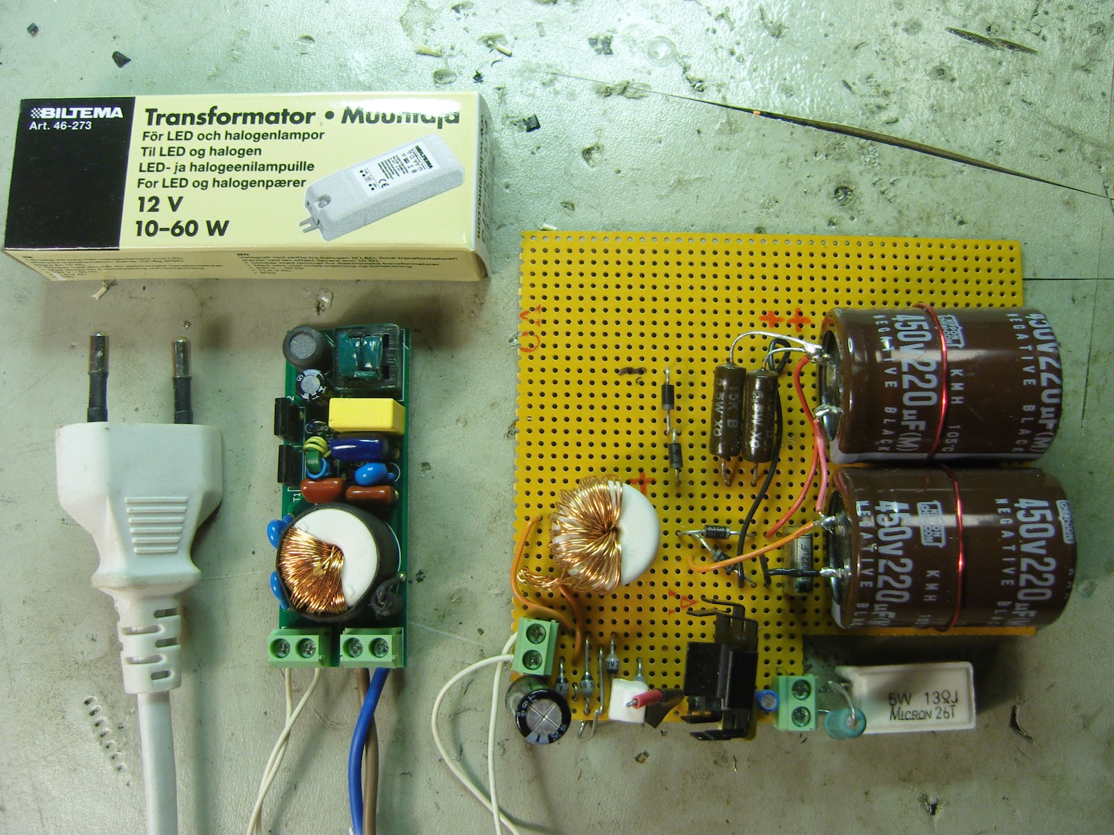
The circuit is based on an electronic transformer for LED or halogen lamps. Electronic transformers usually have a minimum power rating, below which they will not start. This one can tolerate a lower load than most and gives out 12 Volts for a load from less than 10 W and up to 60 W.
My target circuit is the AA8V/W8EXI 6CL6 one-tube transmitter (5 Watts or so). It needs 6.3 Volts for the filament (0.65 A), about 350 Volts DC for the plate and a regulated voltage of 200 Volts DC or so for the screen.
First I was inspired by DL2YEO and his Power Supply for small Tube Amplifiers. His approach was to redesign and rewind the high-frequency transformer (hmm, also a transformer, albeit a tiny one) of the circuit in order to get the desired high and low voltages. It takes some research to find the number of windings per volt and then to fit two secondary windings on the transformer which originally only had a single one. I tried this, but ended up with a burnt, shorted circuit. I concluded that it is too easy to make a mistake in this way.
My second approach was to reuse the small transformer from the burnt supply. I had to wind the original secondary back on it. The transformer is now reversed so the old secondary is used as the primary winding in order to step up the 12V AC. Then with a voltage doubler and filter capacitors I was able to get a DC voltage of 330 V. A series resistor and two 100 V Zener diodes in series gave me the regulated screen supply.
![]() The filament voltage is obtained from the 12 VAC, which is rectified and regulated with a LM317 voltage regulator to give 6.3 VDC. This is shown in the lower part of the veroboard where a load resistor that simulates the tube’s filament is attached to the green terminal block.
The filament voltage is obtained from the 12 VAC, which is rectified and regulated with a LM317 voltage regulator to give 6.3 VDC. This is shown in the lower part of the veroboard where a load resistor that simulates the tube’s filament is attached to the green terminal block.
Because the whole circuit runs at about 45 kHz, only fast-recovery rectifiers can be used, not the ones that are used at 50/60 Hz. The electronic transformer is from the Nordic retailer Biltema (part no 46-273, sorry no English web page).
I only hope now that this power supply won’t generate a lot of noise for the receiver.
Nostalgia from LA3ZA in 1949
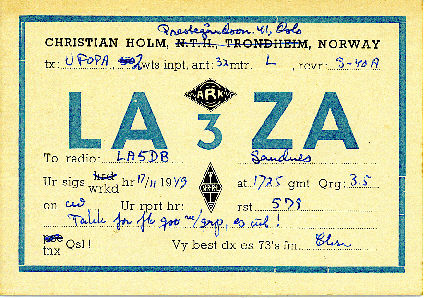
Those who are familiar with me will know that I wasn't even born when this LA3ZA QSL-card was issued in 1949. This is because I am second generation LA3ZA after my father. When the callsign was reissued to me in 2001 it had been inactive for 40 years or so.
I still have the Hallicrafters S40A receiver which my father used with a 2 W input homemade tube transmitter. The S40A (image below) was what introduced me to shortwave listening during the good conditions of the solar peak in the late sixties, despite its mediocre performance I would say.
Read more »
Vertical antenna on a turf roof
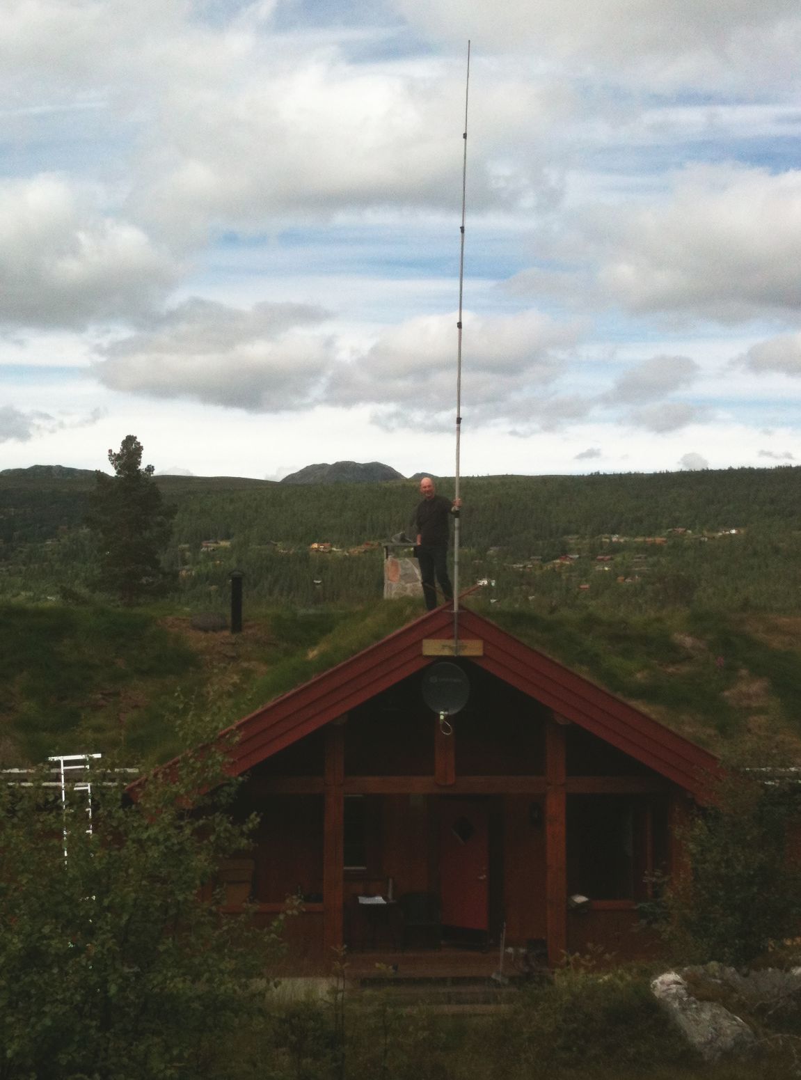
A vertical wire antenna based on a MFJ-1904H 6.7 m (22 feet) telescopic fiberglass pole as shown here is easily tuneable for all bands from 40 m to 10 m. Here it is placed on top of a turf (sod) roof with quarter wave radials for all the 7 bands going to each of the two sides sloping down as they follow the contour of the roof. The antenna seems to work satisfactorily at least on the 30, 20, and 17 m bands which I have been able to test so far.
A turf roof is a traditional Scandinavian type of green roof covered with grass. It dates back to the Viking age and before. In modern times it has seen a renaissance in e.g. mountain cabins.
But how does the turf affect the antenna or to pose the question more precisely: Can it be used to improve the ground plane and the antenna’s performance?


