Posts Tagged ‘qrss’
 On Making Nanowaves – Part 6
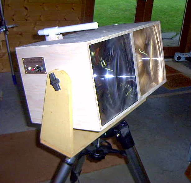
After the transmitter and the receiver had been accurately focused (the receiver's photodiode at the fresnel's focal point and the transmitter's secondary lens properly positioned) both enclosures were screwed together and mounted on a tripod.
Markus, VE7CA, had checked-out a suitable location not far from his home QTH on the road to one of the local ski-hills. This gave him an unobstructed view to my location on Mayne Island, about 54km to the southwest. I had planned to set up in my front yard, about 15' above sea level and on the eastern shoreline with a direct shot to Markus.
Even though we were using LEDs rather than lasers, I still felt somewhat uneasy as our path crossed directly over the runways at Vancouver International (around the path midpoint) as well as the main ferry lane between Vancouver Island and the B.C. mainland. Considering the distances involved, I probably need not have worried as the light, although bright, would cause no physical harm other than possible momentary distraction or curiosity. If one of the ferries had been approaching the path, I had planned to shut down until it had passed as it would have been hard to convince authorities that the light really was not a laser, before they carted me away!
After waiting for the usual winter B.C. rain to subside, we finally had a promising evening shaping up, although somewhat cold. Markus, accompanied by Jim, VE7BKX, loaded his vehicle and headed for the mountains. With neither of us having 2m portable radios, we somewhat guiltily reverted to cellphones to announce setting-up status.
 |
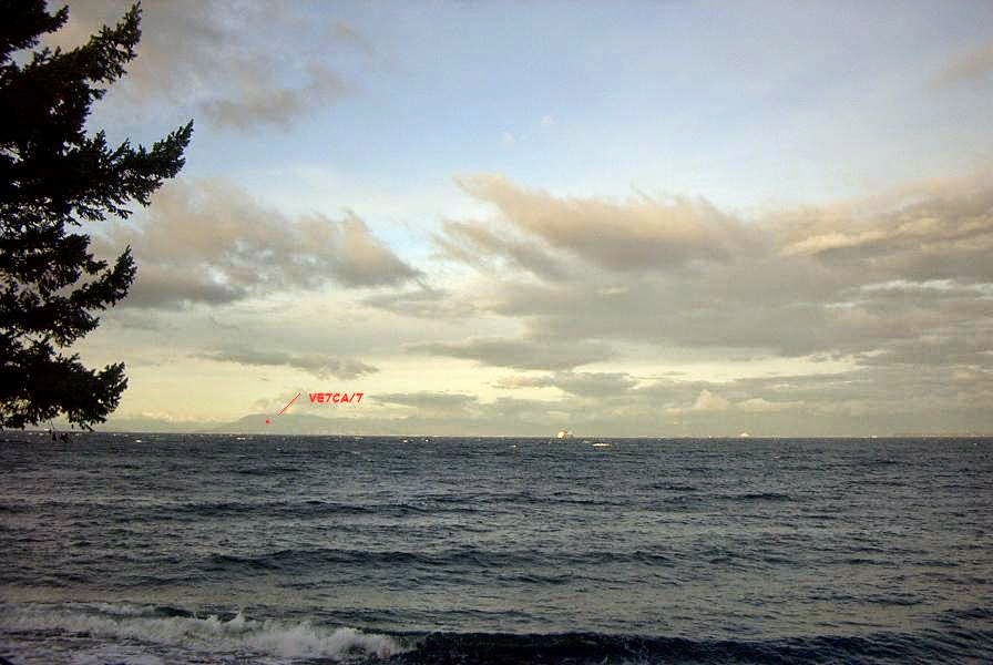
| VE7CA/7 |
Almost immediately I heard his beacon signal although there was no visible sign of his light.
Before final alignment I made a quick recording of his signal.
Neither if us had any real idea of what type of signal strength to expect and we were both very surprised to hear how strong the signals were. Once we had both aligned and our lights were now visible, we switched to CW mode and proceeded to work each other in typical QSO mode.
Hear is a recording of Markus sending my RST report.
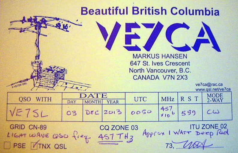
Signal reports as well as grid squares were exchanged just to make everything 'official'. We then settled into a nice twenty-minute ragchew until the cold winter air took its toll on our fingers forcing us both to close down and pack up for the night.
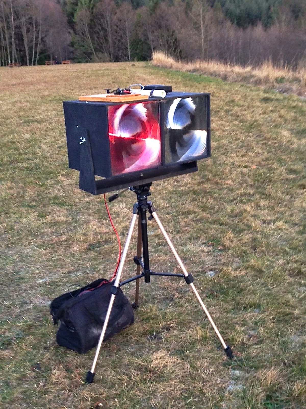
Markus grabbed a short cellphone video from his end which shows the still fairly bright twilight skies and the LED signal source:
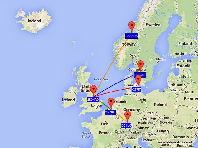
Earlier, John (VE7BDQ) had made the decision to not build a transmitter as he preferred not to go portable. Both of us were interested in pursuing a possible non-line-of-sight (NLOS) path by using either 'cloudbounce' or 'clear-air scattering' which would allow John to set up in his backyard. The path between us is much shorter than the VE7CA/7 path as can be seen in the map below:
 |
| Courtesy: https://maps.google.ca/ |
For one-way beaconing, I plan to add a more accurate crystal-controlled tone module so that my CW signal's frequency is precisely known and can be watched for in the very narrow bandwidth window of Argo or Spectran over a given period of time. Even at these slower speeds, QSOs exchanging the minimum required information can still be made relatively quickly. Hopefully any reception at all of my signal at John's location will excite him into building a transmitter as well. Completing a two-way contact using the NLOS mode would be a very interesting challenge.
In the meantime, Markus and I have been seeking out possible new locations for his remote work, using "HeyWhat'sThat Path Profiler" web site. This site quickly indicates the distance and headings between any two points and draws a geographic contour of the path showing any obstructions.
 |
| Courtesy: http://www.heywhatsthat.com/profiler.html |
Markus hopes to get out to one such favourable location in the Fraser Valley mountains, before the weather turns nasty once again.
If there is anyone in the Vancouver lower mainland region that might be interested in building a lightwave station to join us in the fun, please do not hesitate to make contact with any of us...we would love to hear from you!
If you are a member of the Radio Amateur's of Canada (RAC) and receive their 'TCA' journal, please watch for our upcoming article in September's issue..."A West Coast Lightwave Project".
Ultimate U3 beacon

Thank you very much, Konstantinos .
Now, all I have to do to find the yahoo group and sutable power suply.
Using the Ultimate3
Until now it has been attached it to a dummy load with the FUNCube Dongle Pro+ SDR in close proximity as a receiver for experimental purposes.
One unresolved issue was it being consistently off frequency. The DDS modules used are prone to temperature fluctuations and component variances so the Ultimate 3 has the option of using a GPS module to provide both an accurate time source and an accurate 1PPS input which can be used to self calibrate. Except in my case it had proved to be unreliable.
I am using one of the inexpensive GY-GPS6MV2 modules containing the U-Blox chipset I posted about previously with the additional tap off to provide the 1PPS TTL signal.
Initially the GPS module was connected in close proximity to the Ultimate3 but struggled to maintain lock probably due to interference from the DDS module. Even when lock was achieved the calibration never seemed to work. I posted a question on the yahoo support group and from the answers I verified the calibration setting were correct so the only likely culprit was the quality of the 1PPS signal.
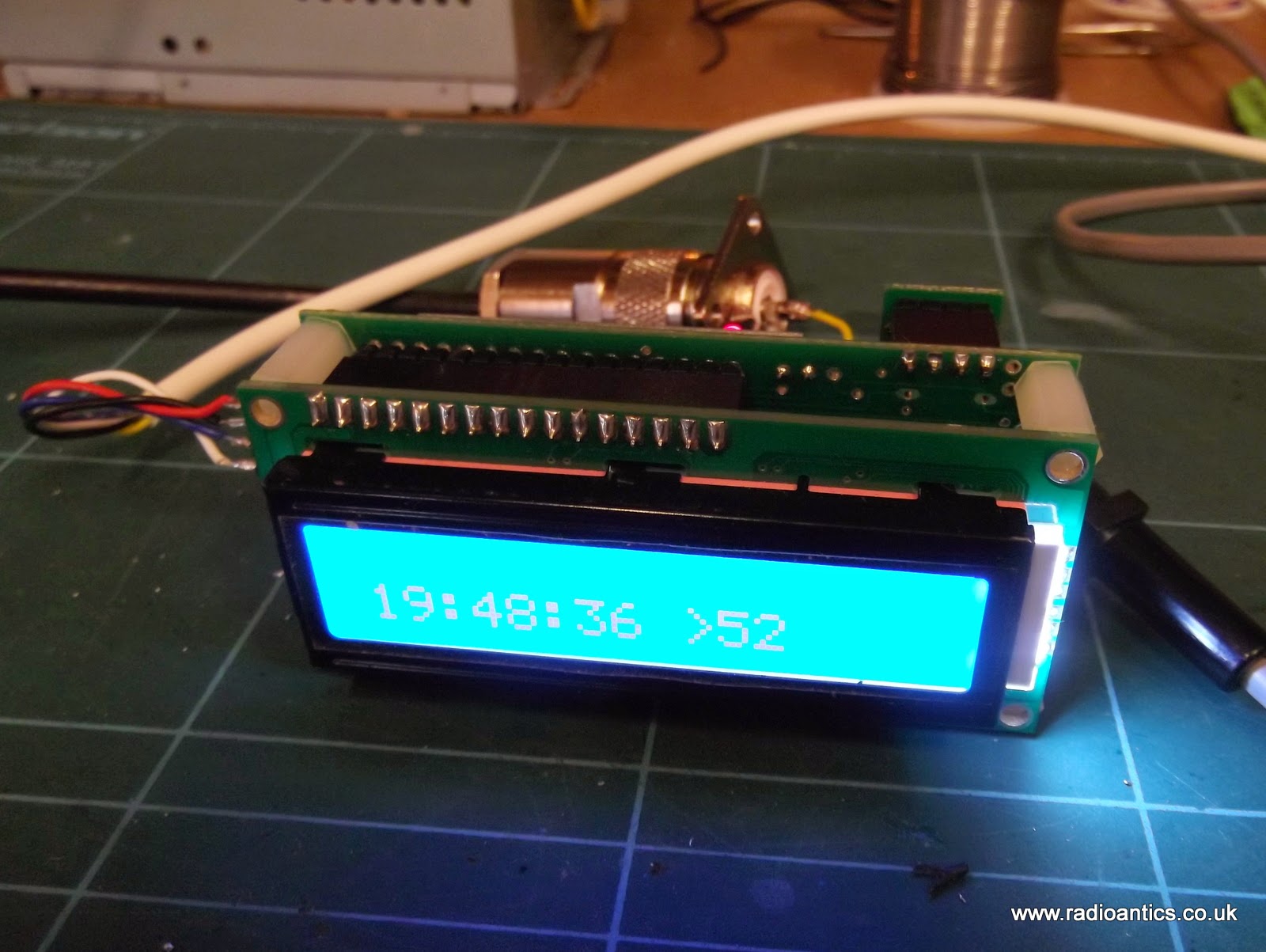
The serial NMEA sentences and the 1PPS signal from the GPS are likely to be required in other planned projects, such as an 'shack clock' and a GPS disciplined frequency standard. So I decided to put the GPS module into a waterproof housing that can fitted on the shack roof in clear view of the sky and away from any potential interference. A multi-cored cable supplies power and the TTL RX/1PPS signals being fed back to the bench.
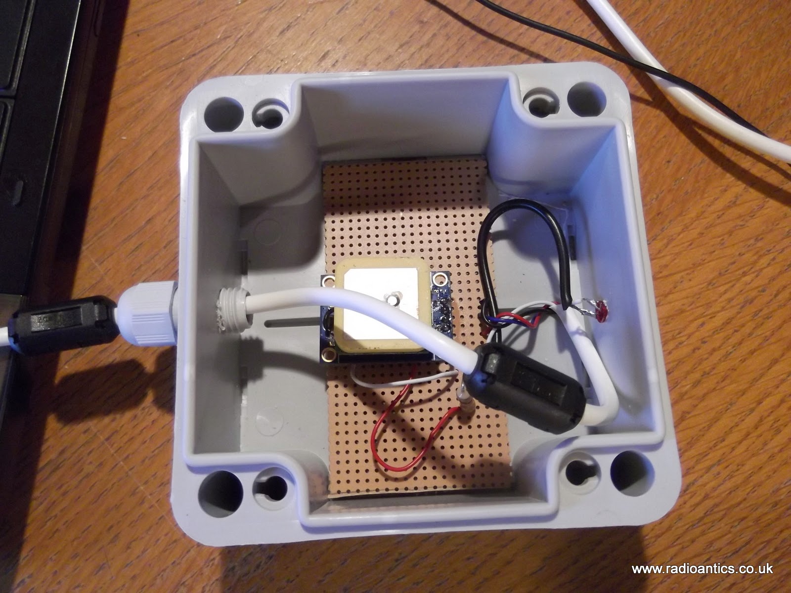
Sourcing an inexpensive weatherproof enclosure (£2) and waterproof cable gland were straightforward enough. I mounted the GPS module on a piece of strip board and replaced the on board LED with one mounted in the enclosure so I easily determine if the GPS had achieved lock, since it only flashes when it has. The LED is sealed with epoxy resin. It should be noted that the outputs of the U-BLOX chip are only rated at 10mA so bear it mind when selecting an LED and calculating the current limiting resistor. The connecting cable is some surplus unscreened alarm cable fitted with a couple of ferrite clamps.
The GPS now has no trouble achieving lock and quickly sets the Ultimate3 clock. Researching the 1PPS problem I hadn't come up with anything definite, as the signal looked okay on the oscilloscope. But I decided to fit a 10K resistor pull up resistor between the 1PPS output and the 3.3V supply on the GPS module. If this actually made the difference I have no idea but the Ulimate3 now successfully calibrates the DDS using the GPS.
At the moment I have configured the beacon to run WSPR and I have been spotted by other operators. Initially I wasn't getting much RF out of the device and it turned out to be a combination of poor connection caused by me not removing the enamel properly on a toroid winding and an iffy antenna connector. Both have been corrected and now get a measurable deflection on the SWR/Power meter. With the additional of a second power amplifier FET it is around 200-250mW.
I purchased the Ultimate3 with a low pass filter for the 40M band and while I have had some European spots the results have been a little disappointing. 40M has turned out to be almost unusable at my QTH due to QRN/M so not sure if that is having an effect, also the antenna I have isn't naturally resonant on 40M so is going through a tuner which will certainly be introducing some losses, without the tuner the FETs get very warm!
With this in mind I have purchased some additional LPFs for the 30M and 20M bands and the LPF relay switching board for the Ultimate 3 so can try/run multiple bands.
QRSS v3 kit
Before the decking project was formally sanctioned and actioned through the domestic funding board / xyl I had thought about ordering a little kit to build over the summer. I had built the v2 QRSS kit from Hans Summers, G0UPL and have used it on the 30m band and frankly enjoyed both the built and the fun tinkering with it.
The v3 kit changes the design slightly in as much as it used a more common 16×2 LCD and the PCB size as increased slightly. But from what I can tell there is a deal of difference between the two designs. Both encourage the builder to tinker with the PA’s, increase functionality with GPS and use the add on LPF relay to build a multi band TX. The one big and obvious change is the used of the dedicated DDS.
Plans for this kit are to still do the build and then buy up 10 kits and build them at the BEC fab lab one Saturday. I will no doubt get a suitable date for the build day at next weeks club meeting. Until then its finish the decking or be in trouble with the domestic CEO.
Cheap GPS module
Most GPS devices have a limit on the altitude they work at, normally 60,000 feet or less. This is a legacy of the now defunct CoCom (Coordinating Committee for Multilateral Export Controls) restrictions. For my HAB project this restriction needs to be disabled and the GPS must be switched into 'flight mode' In the HAB community the favoured devices are made by U-BLOX
Therefore when I was sourcing a GPS I had search specifically for a inexpensive device using a U-BLOX.
 s s |
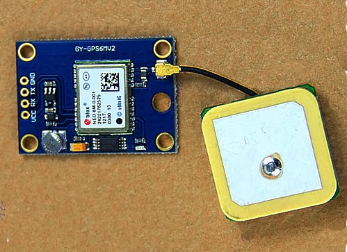
| The GY-GPS6MV2 as supplied |
It is also available from domestic suppliers but often at a much more inflated price, but you don't have to wait several weeks for them to be delivered.
There are many other GPS modules available but this module seems to be one of the cheapest available. it is often listed as a NEO6MV2 GPS Module Aircraft Flight Controller.
The module consists of a small PCB 25mm x 35 mm size with a separate ceramic antenna connected by a small lead which is 25mm x 25mm in size. The Antenna is quite heavy and isn't suited to Pico HAB payloads but for other uses is more than satisfactory.
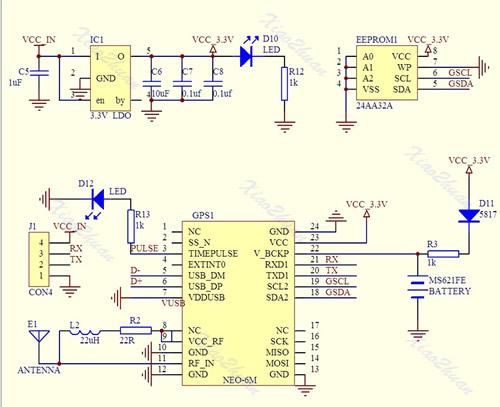
On the board is a small button-cell battery to provide backup to the GPS chip and a small EEPROM connected to the GPS chip which I believe can store configuration(s). I haven't used it myself just using the module in it's default set up at the moment. For a schematic click here
The board has four connectors VCC, GND, TX (Transmit) and RX (Receive) and can be powered by the 5V supply on Arduino boards since it has a small regulator to provide the 3.3V needed.
In most projects all that is required is data out of the GPS. The GPS TX (data out) being connected directly to the microcontrollers RX (data in) The (0V and 3.3V) level shift of the signal is compatible with the TTL input of the microcontroller.
The GPS by default will start up and output standard NMEA sentences at 9600 Baud, until GPS position lock is achieved the NMEA sentences won't have a long/lat location. The module also has an LED which will start flashing once a lock is achieved.
There is no direct connection for the highly accurate 1PPS (pulse per second) signal that can be used for frequency calibration, but the flashing LED is driven by pin 3 of the GPS module which is the 1PPS (pulse per second) signal required.
The 1PSS signal, like the TX is either 0V and 3.3V, in order to use it a small lead will need to be soldered onto the board, either directly onto Pin3 of the GPS chip, or alternatively on to the small current limiting resistor used by the LED, as indicated below.
 |
| Showing the GPS 1pps points |
FUNCube Decode Issues
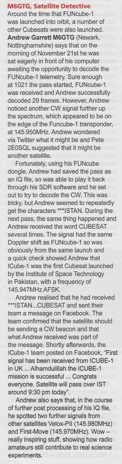
I also had a small write up in Tim Kirby's (G4VXE) VHF/UHF section of the February issue of Practical Wireless about my I-Cube1 reception which I have mentioned on here before.
I haven't progressed very far with my Arduino projects. There has been a set back in the plans to build and use an Ultimate3 QRSS kit. I had incorrectly assumed as it was a kit being sold commercially that it would satisfy my foundation conditions. However I have been advised that Foundation license holders may use radio equipment constructed using commercially available kits which satisfy IR 2028 which is all a bit vague and woolly, but I don't believe this particular kit does.
There is a simple solution, I will just have to take my intermediate assessment and exam at the first opportunity!
I have been doing a little WSPR spotting, getting some nice spots.

Over the Christmas/New Year period I have neglected the FUNCube-1(A073) satellite and was slipping down the telemetry upload rankings, sad I know!
Now I have got back the upstairs 'shack' I set up my original FUNCube Dongle on the laptop running the dashboard application continually to capture/decode the telemetry using the loft mounted discone. I took the opportunity to upgrade to the latest version 8.14 of the dashboard software, however something was amiss when checking the statistics I was only adding the odd frame here and there, sometimes not making a single decode during the high power daylight passes.
I switched back over to the newer FUNCube Dongle PRO+ running my main PC, which I had also updated to the version 8.14 dashboard and saw the same behaviour, rather than getting daylight decodes of 30+ frames I was just getting the odd 1 or 2.
My first thought it was an antenna or interference issue, but checking the SDR waterfall the signal is still very strong with little QRM. Suspecting a software issue introduced by the update I checked the FUNCube forum and found a thread which appeared to confirm my suspicions.
I have a number of discussions on twitter with various people including David Johnson (G4DPZ) an AMSAT-UK Committee Member and one of the developers of the FUNcube ground segment. David kindly performed an analysis of one of the passes yesterday where I managed just 2 frames, and from the results it does appear to be an issue at this end, rather than issue with the spacecraft.
I have uninstalled v8.14 and put back on an earlier version of the dashboard (v8.09) and thanks to a windows update last night have also performed a full reboot!
There was a good pass this morning at 62 degrees maximum elevation (to the east), followed by a lower pass at 22 degrees elevation (to the west so not so good) and it seems things have improved managing 68 and 17 frames respectively. So could this be an issue with the latest dashboard?
If anyone has suffered similar performance fall-off, or indeed not suffered any issues then please add some feedback to the FUNCube forum.
My copy of Radcom arrived but didn't have much time to read it..
 |
| The culprit! ;-) |
Arduino, WSPR and AD9850 DDS experiments
Christmas is thankfully behind us so I can get back to what I enjoy doing once I have reorganised my workshop.
As you know I am currently developing a potential High Altitude Balloon (HAB) project and have been experimenting with the Arduino microprocessor platform and have constructed a basic prototype.
With the arrival of the GPS module(s) I have had it successfully working and even took it out for a test walk in the local area, receiving the data and uploading it to the UKHAS habitat system.
NERD-1 and Boris have just been for a walk, first time NERD-1 has had proper GPS and running on batteries. #hab pic.twitter.com/RaKsf1rQhr
— Andrew Garratt M6GTG (@nerdsville) November 23, 2013 This project has revitalised my interest in 'hobby electronics' and I have ideas for a number of other Arduino based projects and have been splashing out on components from eBay. Just before Christmas I purchased an Arduino Mega board, this has more I/O pins than the current Uno and specifically some extra hardware serial ports.
Do any internet search for Arduino based amateur radio projects and it will results in numerous mentions of projects using ultra cheap DDS modules based on the Analog Devices AD9850/AD9851 chipsets.
DDS means Direct digital synthesiser and is a type of frequency generation which can be used for creating arbitrary waveforms from a single, fixed-frequency reference clock. Read the Wikipedia page for more details.
In a nutshell the AD9850 is a chip that under microprocessor control can produce a sinusoidal wave from about 1hz to 40mhz. In other words it is an accurate microprocessor controlled VFO (Variable Frequency Oscillator) or signal generator.
VFOs are the main building blocks of radio receivers and transmitters, so not surprisingly a lot of projects have utilised these modules, rather than the traditional means. Intrigued I ordered a couple of these modules for the pricey sum of £3.50 each!
Using information on George Smart's (M1GEO) website and Simon Kennedy's (G0FCU) blog I quickly had a simple WSPR beacon running!
Experimenting with Arduino and AD9850 DDS and GPS unit.. pic.twitter.com/rxDHQQ1aFd
— Andrew Garratt M6GTG (@nerdsville) December 29, 2013 The Arduino uses the GPS module borrowed from NERD-1 for accurate time and then controls the output of the AD9850 DDS to generate the WSPR signal.Before anyone panics I know at the moment I only hold a Foundation Amateur Licence so the construction of homebrew transmitters isn't allowed. This 'beacon' has no power amplifier and the antenna consisted of an inch or so of wire on the DDS output. I was able to verify the operation using my SDR receiver in the same room.
Construction of commercial kits is allowed under my licence so I have ordered a Ultimate3 QRSS kit from Hans Summers for the pricely sum of £17.50! This uses the same DDS module and same microcontroller as the Arduino.
In the meantime there is also more information and ideas on Eugenr Marcus' (W3PM) webpage about the use of these DDS modules, including making frequency reference sources and calibration using the GPS module.
My new year resolution is to get my Intermediate Licence as soon as possible.. but it has been great to get down to some proper experimenting...
Cannot beat a picture of an oscilloscope to look techy.. my DDS experiments continue... pic.twitter.com/T9OLHOdTLW
— Andrew Garratt M6GTG (@nerdsville) January 1, 2014 


