Posts Tagged ‘qrss’
 QRSS experiments: FSKCW and Slow Hell
These last few days I’ve been experimenting with my QRPLabs Ultimate 2 and Ultimate 3s transmitting on 7 MHz. In addition to WSPR, the modes transmitted have been FSKCW with 6 second long dots, and Slow Hell with 17 second long characters. The result as received this morning can be seen on the display from the grabber of Les, G3VYZ in Northumberland, UK. This is a stack of 6 consecutive 10 second frames as can be found on the QRSS grabber site of AJ4VD.
 |
| FSKCW and Slow Hell reception of LA3ZA at G3VYZ |
My signal is on 7,039.870 kHz and has been set up with a FSK shift of 6 Hz. Power output was 0.2 W and the distance is about 890 km.
It works but the reception is much less reliable than for WSPR, which is not so unexpected. At the same time the WSPR signal was received all around Northern Europe (G, GM, DL, OON, OE, LX, LA, OY, OH, PA, SM) as well as on the Canary Islands, 3930 km away.
New Lightwave Modulator
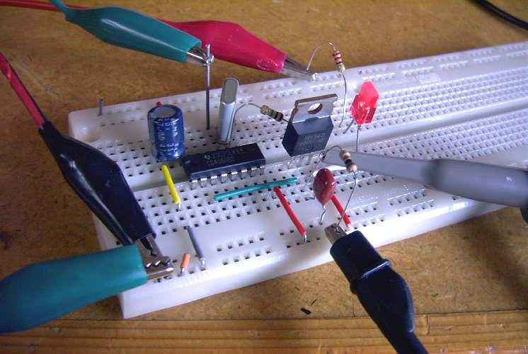
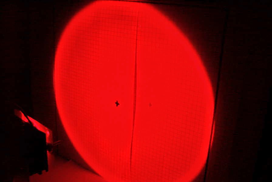 Yesterday I completed the construction of the crystal-controlled tone generator which will be used to modulate my lightwave transmitter during future clear-air / cloudbounce tests.
 It was installed on the lightbox, right beside the original 556 CW beacon / tone generator.


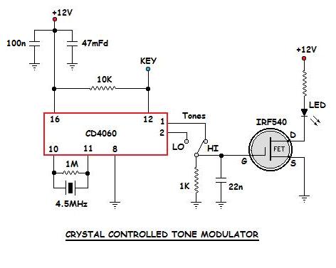
The crystal-controlled oscillator uses a CD4060 IC as an oscillator-divider and produces a ~550Hz or a ~1098Hz squarewave from the 4.5MHz crystal.
 |
| 4500KHz xtal divided by 8192 showing 549Hz output |
As can be seen by comparing the two oscillators (crystal on the left and 556 on the right), the 556 has a lot of drift (although it looks like it might eventually stabilize) and, as well, produces several spurious signals ... probably robbing power from the main tone. The crystal-controlled signal is rock solid and doesn't appear to generate any parasitic signals in the process. The trace below the crystal signal is unrelated to the oscillator.
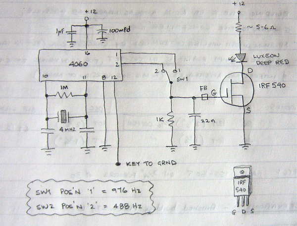
When I first wired the unit up, I found an unstable low frequency oscillation from the 4060 during key-up conditions, due no doubt, to the lengthy leads inside the box. This was cured by adding a pull-up resistor to the keying line as shown in the final schematic below.
Now it's on to building another fresnel-lens receiver box which will be needed for any field work here on the island.
Lightwave Scatter
As it is at present, the modulator consists of a 556 tone generator, capable of either a steady tone for CW keying or a two-tone FSK 'beaconing' signal used to help the other station in aiming alignment.
For the slow QRSS CW narrow-bandwidth modes required for the scatter tests, I've always known that a tone which is much more stable and of precisely known frequency would be needed. The tone from the 556 does well as an aural CW keyed tone but would probably be all over the place when viewed in a very narrow-bandwidth and not nearly as stable as it sounds by ear.
The little modulator uses a 4500 KHz crystal (pulled from a old VCR several years ago) in a 4060 oscillator-divider. In this case, output from the chip is taken from either the 'divide-by-8192' pin 2, which outputs a precise frequency of 549 Hz or from the 'divide-by-4096' pin 1, which outputs a frequency of 1099Hz.
 |
| courtesy G3XBM: http://g3xbm-qrp.blogspot.ca/search/label/nlos |
This tone is then used to drive an IRF 540 power MOSFET which controls current through the 1W Luxeon Deep Red LED in the transmitter. The 4060 modulator will be keyed via a QRSS software keying program that I have used for many years to key my LF transmitter.
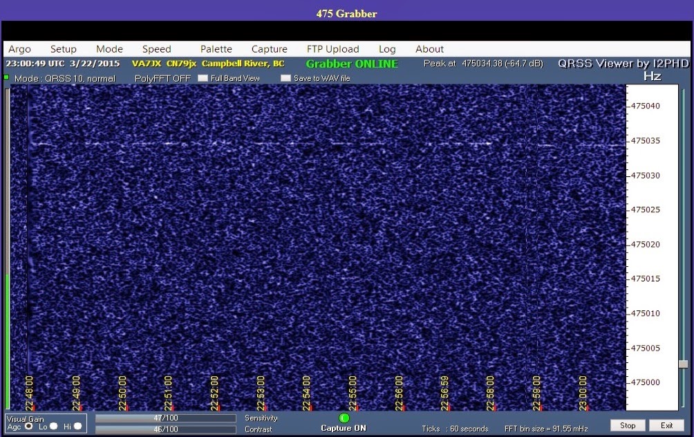
The lightwave receiving station will look for the QRSS audio signal with an audio spectrum viewer such as Argo or Spectran. The ability to make automatic overnight screen captures will allow the receiving operator to get a good night's sleep while the system diligently watches for any traces of a signal.
An example of a strong signal capture showing a repeating "SL" identification is shown below, as it would appear in a perfect world. In this case (QRSS3), the short 'dots' are 3 seconds long while the 'dashes' are 9 seconds.
Huge signal gains (the ability to dig into the noise for signals) can be had by slowing things down and using narrower receiving bandwidths. Just going from a normal 12WPM speed CW (aural copy) to QRSS3 yields a gain of ~15db. At QRSS10 (10 second dots), an additional 5db is gained while slowing to QRSS60 (60 second dots), a whopping 28 db over 12WPM CW is gained!
Of course all of this extra 'hearing power' comes at a cost and in this case, the cost is 'time'. On an overnight of automated computer monitoring, time is not much of an issue ... it only becomes critical in 'QSO mode' when some QRSS QSOs can take several hours to complete. In any case, it will be interesting to see if any traces of lightwave signals will show up while bouncing around in the clouds.
The Georgia Strait scatter tests will not take place for some time but in the meantime, I hope to do some local tests here, from one side of my island to the other but will build a new portable receiver for these tests and leave my main system intact.
A 630m QRSS Test
Mark was transmitting on 630m at a power of just 144mW output, while Jack was receiving on his normal 630m inverted 'L'. Mark tried various QRSS speeds ranging from QRSS3 (3 second 'dits') to QRSS60 (60 second 'dits'). One can clearly see the difference between the three speeds.
Going from the relatively slow CW rate of 6 WPM to just QRSS3 alone, produces a healthy 12db increase in signal level. Going from there to QRSS10 produces another 5db, while going all the way to QRSS60 produces a whopping 24.8db over 6 WPM CW! The trade off, of course, being the amount of time it takes to send the needed information.
In practical terms, contacts can be made relatively quickly at both QRSS3 and QRSS10. After that it becomes a bit of a chore as conditions need to be very stable for long periods of time ... as well, you'll need several hours to complete a two-way exchange.
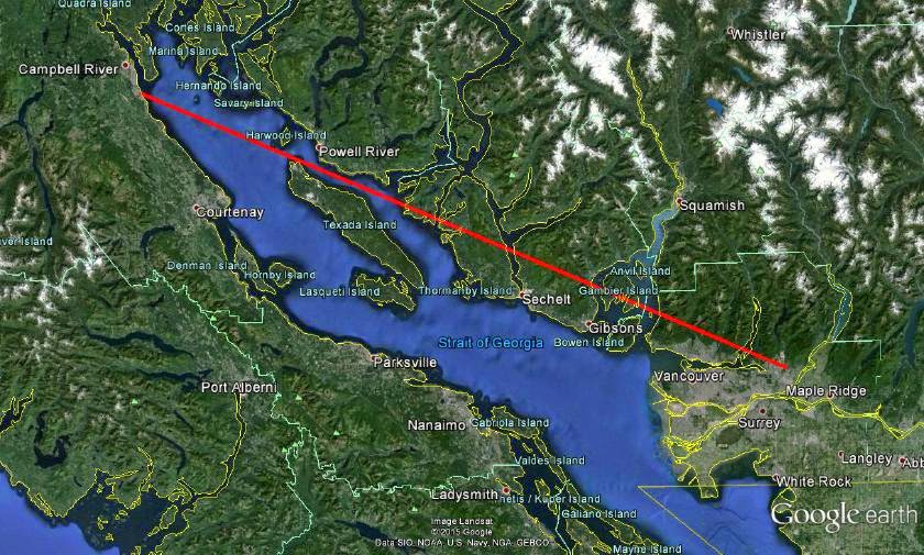 | |
| courtesy: https://www.google.com/earth/ |
 | ||||
| VA7MM - QRSS3 |
 |
| VA7MM - QRSS10 |
 |
| VA7MM - QRSS60 |
 |
| courtesy: http://www.heywhatsthat.com/profiler.html |
I should add that Mark's transmitting antenna is very minimal at the moment, consisting of an 80m dipole fed as a vertical 'T', tuned but not impedance-matched and ... no ground radials. Pretty remarkable actually.
630m Resources – Part 2

Using the transverter approach offers the advantage of providing a higher-stability signal generated by the main station's transceiver oscillator system. Most of the digital modes require a higher stability than would be needed for straight CW.
If your main interest is normal speed CW, then a digital VFO, such as the one devised by GW3UEP, would do the job.
If you are content operating on 475.0 kHz, then an inexpensive 7.6MHz crystal, in a divided-down oscillator will work well, and with good enough stability for some QRSS work as my earlier "GW3UEP Transmitter In QRSS Mode" report indicated.
The other option for frequency generation is a DDS.
 |
| N3ZI DDS |
For those wanting something a bit more robust, W1VD describes a very nice high-power transmitter. His website is packed with useful circuits and ideas for both 2200m and 630m.
 |
| W1VD Dual-Band Kilowatt : http://www.w1vd.com/ |
W7IUV also describes, in great detail, his method of generating high-power on 630m. There is much to be learned from his document describing the design and operation of his unique 'linear-mode' transmitter.
 |
| W7IUV 630m TX: http://www.w7iuv.com |
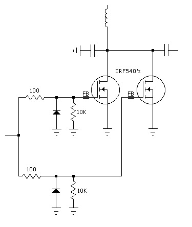
Another practical way of generating moderate power, certainly enough to meet the Canadian 5W EIRP limit, is to combine two or more 100W transmitters, such as the GW3UEP transmitter. It is reasonably simple and inexpensive to combine several modules with the use of a homebrew power combiner, as previously described.
 |
| Homebrew 630m two-Port Power Combiner / VE7SL |
GW3UEP 630m Tx Complete

Added to the panel were a 5A DC meter to monitor drain current, a keying jack and a key shorting-switch for keydown testing. This is the third version I have built using the design on Roger's page, with all three performing pretty much as advertised. It is an inexpensive, easily reproducible design.

Smoke Testing The GW3UEP 630m Transmitter
 |
| Drain (top) vs Gate (lower) on testbed Class-E GW3UEP TX |
I've just completed the Muppet-styled printed circuit version of my previously breadboarded GW3UEP 630m transmitter. The earlier version was built "ugly style" in order to optimize part values and measure circuit parameters.
 |
| Testbed (Ugly-Style) |
 |
| Final Version (Muppet-Style) |
Running the TX at 12.8VDC on the drain(s) at 2.3A produces an input power of 29W. The measured power out, after the LPF, is 23W into a 50 ohm load. This represents an efficiency of 80%. When run in the normal speed CW mode, the FETs run cool enough that they would probably not even need a heatsink but if run in any of the QRSS (long keydown periods) modes, would certainly benefit from heatsinking.
Running the TX at a higher voltage of 22.6VDC (on the amplifier only) yields a current of 4A for an input of 90W. Measured output power is 71W for an efficiency of 79%.
Heatsinking would be required at this power level, even for normal speed CW but the finals seem to run just slightly warm. A larger heatsink or possibly a small fan as well would be required for any QRSS CW modes.
I suspect that the efficiency could be further improved yet with very fine tweaking of the output circuit L/C network but the extra few watts gained would not be significant.
At either power level, this easy-to-build transmitter would make a great "first 630m transmitter" for anyone wanting to get started on our new band.


