Posts Tagged ‘Magnetic Loop’
 In The Loop! – First Impressions of the MFJ-1788
 |
| Temporary test setup |
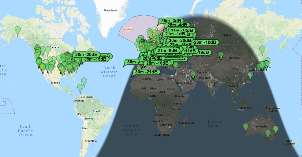 |
| PSKReporter showing where I was spotted |
I had a few more sessions and a few days later I tried it out to receive the Shortwave Radiogram broadcast from Bulgaria on 9400kHz, this time as it was a broadcast band had to use my ear to do the tuning, adjusting till I heard a rise in 'noise' and signal.
I have now got the loop up on a rotator and mounted slightly higher up with a shorter length of RG213 (not on the video) it is still quite low and unfortunately is slightly shielded to the south by the neighbours metal roofed building,Trying out the loop antenna, @SWRadiogram— Andrew Garratt (@nerdsville) May 19, 2018
images this afternoon from Bulgaria 9400kHz pic.twitter.com/53HRwIHUQz
I am very happy with the loop. Transmission wise it unsurprisingly doesn't seem a huge improvement over the OCFD on its resonant bands, it scores over the OCFD is on its 'non-resonant' bands such as 30m and 17m. But the massive improvement is in receiving, signals are stronger and noise is much lower, picking up some more distance signals even given the poor conditions.
The antenna cannot be said to be a pretty thing to have in the garden! The tuning is very particular, in the video I show the 'auto tuning' isn't ideal. It requires the radio to be putting out a signal into a mismatched load for what could be nearly a minute. Not good for the radio and is a source of QRM during this time, the usual technique of tuning slightly off a QSO frequency is more problematic due to the sharpness of the resonance. You can still tune off frequency and then tweak with the slow tune buttons to bring it in. I've noticed that on some of the higher bands it occasionally doesn't auto-tune because the 'dip' seems very short/sharp and the controller doesn't react in time and overshoots especially using low power settings.still evaluating the RX of the mag-loop and according to pskreporter heard 92 countries, 1182 stations on FT8 30m/40m in the last 17 hours.. pic.twitter.com/ZuWZOFFiP2— Andrew Garratt (@nerdsville) May 22, 2018
I also have had issues trying to operate the radio remotely, I have tuned it up on an FT8 frequency in the morning and then later in the day logged in to try to make a few QSOs during a coffee-break to see the loop has drifted out of resonance. This can only be down to the loop getting warm in the summer sun.
I am still evaluating the antenna but am looking at making a better controller, over on AmateurRadio.com where this blog is syndicated, I have had a number of kind comments including one from Elwood Downey, WB0OEW who pointed me to his published design of a controller, using a similar method to what I was toying with. Thanks Elwood.
73 for now, more updates soon.
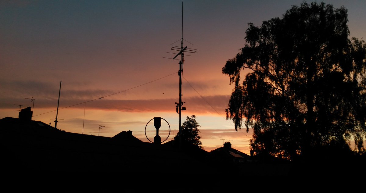 |
| The antenna farm |
In The Loop! – Repairing a MFJ-1788
Earlier this year I spotted a posting on social media by a member of my club who had brought a MFJ-1788 second hand who was having issues with it not working. I had offered some advice on its repair and glibly offered to take it off his hands should he want to dispose of it. A few months later I got a message asking if I was still interested? I certainly was at the price he wanted.
I collect it at the club meeting a fortnight ago still with a 5ft pole still attached as a bonus! Thankfully it fitted in the car (just).
 |
| Loop as purchased, with pvc tape covering loop |
 | |
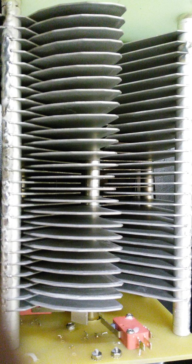
| Control Box |
I downloaded the manual and schematic from the MFJ website and I saw there were conspicuous warnings about using an 'isolated' power supply both in the manual and on the back of the controller, with ominous warnings of damage if you didn't. Most shack supplies have the negative/black pin connected to the chassis/ground.
The controller had come to me supplied with a standard fused lead, you know the ones that come to connect your ATU/SWR meter lamp to the shack supply? Mmmm.. my spider sense was tingling!
I pulled out a small double-insulated 12V plug-in supply from my collection (you can spot them as they often have a plastic earth pin) and with nothing else connected powered up the controller. The meter lamp came on and some of the LEDS briefly flickered and heard a few clicks from the internal buzzer then nothing. Pressing buttons did nothing and then I caught the unmistakable scent of burning electronics!
Opening the box up on the bench quickly spotted the source, the regular had well and truly smoked, but since nothing had been connected the short must have been in the controller itself (and it was not the dodgy wires that look like they had been victims to a wayward soldering iron)

Inspecting the rest of the board it was clear that it had been repaired (badly) once before, the two main transistors/FETs (Q1/Q5) used to control the motor clearly showed signs of being replaced (misaligned and with tell-tale scorching from an hot air gun)
a SMD diode had been swapped and one of the 'fine tune' switches had been replaced, its removal had obviously been problematic taking with it some of the through hole copper and adjacent tracks which had been lifted/damaged.


Before opening up the box I had expected to see 'through hole' components and DIL logic ICs not for it to be all surface mounted. Undaunted I went through the parts list and decided to get replacements for all the semiconductor parts not knowing at this stage what I would have to replace. Getting two of each device in some cases five or ten of each due to minimum order quantity, the staggering cost was £8 ($11) including postage!
While waiting for the parts to arrive I decided to check out the actual antenna head. I removed the plastic covering and attempted to extract it from the pole..

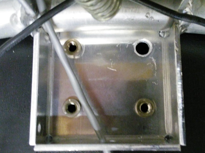
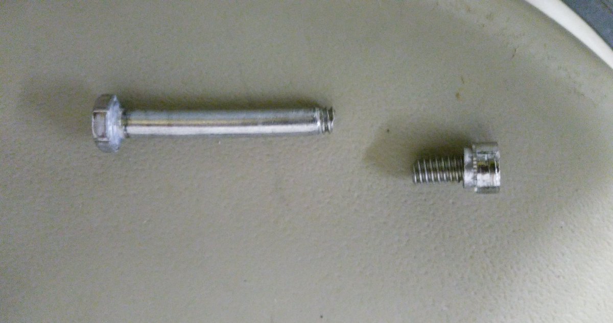
First issue I had was the mounting. One bolt had seized, the nut inserts are held in quite soft aluminium so not surprisingly the insert came out out the mounting when trying to remove it. Using grips to hold the insert the bolt still refused to turn and in the end it sheared off with very little force! Obviously quality fittings these!
The variable capacitor was suffering a common problem due to poor quality control, the fins had gone out of alignment. Each fin is a separate assembly held on a shaft with a nut to compress them together. It is a simple fix, just realigned and tightened the bolt. The limit switches and motor connection were okay (another common problem) Applying a voltage to the coax connector the motor turned fine, reversing the voltage reversed the direction of turn, the vanes going fully in and fully out before the limit switches activated.
The components arrived prompty and so I got the hot air gun out and set about repairing the board.

I started off replacing the regulator (and the damaged power track) and Q1/Q5 and we had the flickering of life. Pressing the AUTO TUNE button the LED lit and there was 9V across the antenna connector, pressing the other AUTO TUNE button had -9V across. This is why you need an isolated power supply since it reverses the voltage to control direction. The radio doesn't see any of this voltage due to the bias-t arrangement. However if the supply shared the shack ground you would short out the supply, but the current would go via all those delicate electronics! Which is what I think had happened.
It soon became clear that most devices had suffered damage and so I ended up replacing the regulator 78L12, Q1 (SN7002 FET), Q2 (MMBT3906), Q5 (MMBT3906) all the logic ICs CMOS 4001, 4011 and 4066 and the LM324 Quad op-amp chip. I also gave the board a good clean since was covered in grime and flux residue.
Once I was happy the controller was reassembled and connected to my FT-857D on minimum power and the loop antenna propped up against the side of the shack. Success! I was able to successful tune it as per the instructions on 40m and 10m, the two extremes of operation and could here the telltale rise in receive noise as it became resonant.
I have yet to put the loop up in situ for a proper evaluation but have refurbished an old TV rotator to mount it on. I have fitted some nice new quality bolts. The black insulating tape round the loop has been removed, preferring the silver look myself.
 |
| Waiting to be put on the pole |
 |
| Shiny once again |
Assuming it does performs and will find out this weekend, I have paid a total of £65 ($90) (£50 for the initial purchase the rest for replacement parts) which is an absolute bargain as to buy new it is expensive.. very expensive!
One of the main supplier in the UK, have it on sale for £699 ($940) but this includes their engineers inspecting and rebuilding each one before shipping! (Can only be due to poor build quality control and warranty claims) the RRP seems to be around £570 ($770)
It does amaze me how much this units costs new. While the loop construction is generally good, the mounting fittings appear to be poor and the issues with the capacitor and quality control are widely reported.
The components in the controller are not expensive, the switches, meter, box are the usual MFJ fare and the design is quite old (the PCB has copyright 1998 on the silk screen) the auto-tune process requires the radio to be putting RF into a mismatched load for up to a minute and even with low power and SWR protection this isn't good for the radio PA.
Perhaps most surprising is given the risk of damage due to incorrect use is why firstly the loop isn't supplied with a power supply anyway as they only cost a pittance and secondary why their isn't any protection built in? I intend fitting a simple 100mA fuse to offer some protection should a problem occurs.
If the loop performs it may be another project to build a better controller, there are a few designs out there on the internet using Arduino and DDS devices to create auto-tuners. Has that pile of potential projects just grows taller?
73 for now.. and promise to post a bit more regularly
Italy & QRPer with a Mag Loop
I thought I might get skunked today! The bands seemed pretty dead – and the wind was blowing 20-25 mph!
I finally did have two QSO’s….
IK2CIO – Vini was calling CQ from Italy. Tried several times and got a 599 report from him – which I suspect was more of a contest style report – but still fun none the less! I worked Vini on 17 meters.
I didn’t hear any other action, so I called CQ on 20 meters at 14.061. A very weak station replied….
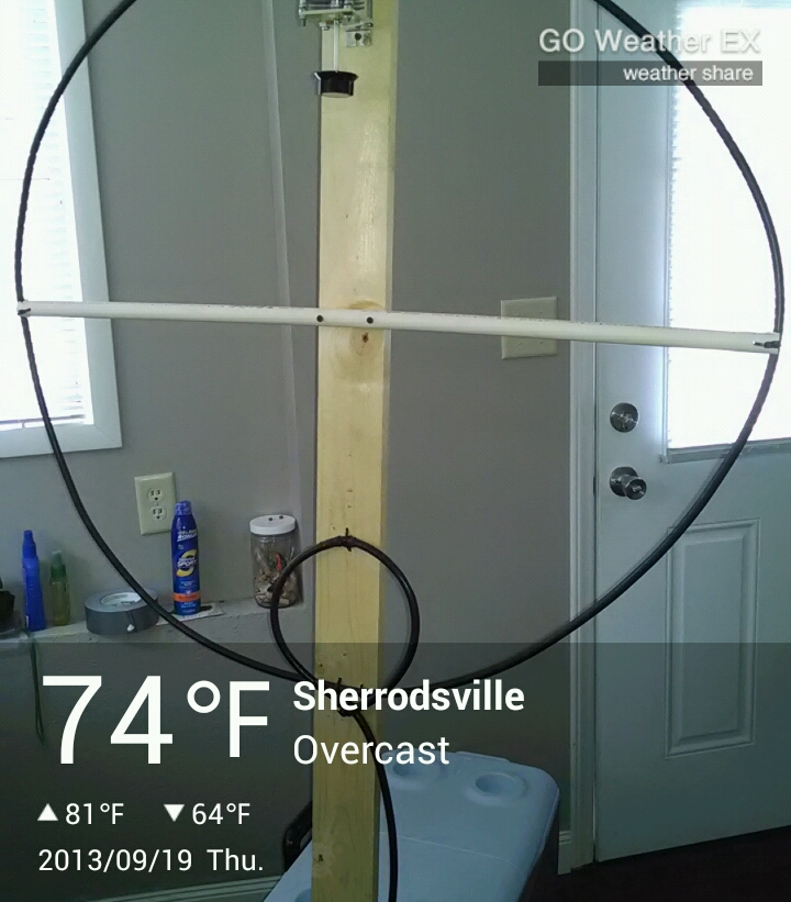
AJ8P – Jeff returned my CQ from Sherrodsville, OH. He was very weak, and then someone started calling CQ really close to us. If I cranked up the filter, I would lose him – so just had to suffer through it. Jeff said he was running 2 watts.
After I got back to work, I had an email from Jeff. He sent me this picture and said he was using the Mag Loop inside! This just makes me want to get one of my loops working so I can start having some radio fun from the comfort of my home.
From checking out Jeff’s QRZ page, he has a couple nice QRP rigs on his page – worth a visit.
Magnetic Loop Construction – Part 1
So I got a little time over the weekend to make some progress on my magnetic loop antenna. I constructed this antenna from 1″ copper pipe in a square shape with 90 degree elbow. The loop is 30″ square.
At this time it will be rockbound on 20 meters, centered around 14.060 – so the bandwidth will be very limited. I want to do this so that I can do some testing before I go all out and convert it into a multi-band loop, which will hopefully work on 20-10 meters (with maybe 30 if I am lucky).
.JPG)
Making the Coax Stub Capacitor
So what I did was take a piece for RG-213 coax and cut it about 30″ long. Then on one end I removed about 2 1/2″ of the shield and pulled the braid away from the core. I taped it all up really well with multiple wraps of electrical tape, leaving about 1/2″ of braid and 1/2″ of conductor (sticking out of core).
After sanding the copper to a nice shine, I took some stainless steel hose clamps and clamped the braid to one side of the loop and the center conductor to the other side.
This piece of coax becomes the capacitor which will be used to tune the loop to the desired frequency. Right now it is longer than needed so it will resonate well below the 20 meter band.
.JPG)
The Feed Loop
I then took some RG-8 and made the feed loop. For my loop size the feed loop is about 1/5th the circumference of the main loop – so about 24″. I added a bit for the coax connector. I decided on a shielded Faraday loop after reading that they are quieter on the mag loop email list.
To construct this loop I formed the circle and soldered the center conductor to the braid at the bottom of the circle. Then at the top of the circle I removed about a 1/2″ of the braid only. I taped up all connections and exposed braid, etc.
.JPG)
Initial Tuning
I quickly taped the Faraday loop to the main loop with some painters tape because I wanted to see how it looked just sitting on the bench. Before I do the final tuning I will hang the loop on the wall of my garage – its final home. I was just excited to see where it was resonant!
So I hooked up the antenna analyzer and started a slow sweep from 20 meters down looking for the SWR dip. THERE IT WAS SWR 1.2 @ 11.131 MHZ – clear as day!
Next Steps
The next thing I am going to do is mount the loop to a piece of 1x wood and then mount that on the wall at its final location. Loops are sensitive to their surroundings, so you always want to tune them at the location they will be when completed.
Then with the analyzer connected I will start cutting 1″ chunks off the coax until I get close to 14 MHZ – the final tuning will be done by sliding the braid up and down the core to get the frequency exactly where I want it.
Once it is operational I will spend some time testing with the Reverse Beacon Network and making contacts. If it works well, ultimately I will construct a butterfly capacitor for tuning and build an Arduino stepper motor controller so that it can be remotely tuned from the shack.
I can’t wait to see how it works and if the noise floor is substantially lower than using my Portable QRP Vertical.
If you would like to construct something similar (although he shows a Gamma Match for the feeding) you should check out W2BRI‘s pages – great instructions with pictures to make everything easy.
Pondering Antennas for the HOA Restricted Home
.JPG) |
| 30″ Magnetic Loop Under Construction |
As the list of major projects at our new home is starting to get shorter, I have been pondering an antenna installation that is more permanent than my Portable QRP Antenna that I strap to the deck railing when I want to operate.
The portable vertical I use, which is nice and quiet at the park, is VERY noisy at the home QTH which is full of all sorts of man made electrical noise.
First thought was to put a 66′ doublet in the attic and feed it with ladder line. I have no doubt this would work, but I have to invest in ladder line to make it happen.
I have a 30″ square magnetic loop that I have built from 1″ copper pipe before we found out we were moving. It is all soldered up, just sitting in my garage waiting for a tuning capacitor and feed loop to be installed. I am leaning towards this being my first antenna install here at the QTH.
Why a magnetic loop?
You can read all about the good and bad of loops online, but one of the biggest drivers is that they are supposed to be very quiet. Many hams that report S5+ noise on their dipoles are reporting S1-S2 noise on the loop.
The other reason is that it is almost done – probably a couple hours of work max and I could have it on the air. Additionally I can hang this in my garage, or put it in the attic, so that I can keep in good graces with the ever watchful HOA observers!
So that is what I am going to do. At first the tuning capacitor will be done with a coax stub tuned to a fixed frequency. I will do this centered around 14.060. This will give me a narrow little spot to play.
Then I am going to build a home brew butterfly capacitor – which I will document here.
Antenna expansion
I know when summer is here when I have to keep on tweaking the tuning of my MFJ magnetic loop antenna throughout the day. Having an antenna farm in the attic (or loft as it is more commonly called over here) protects the antennas from the depredations of the elements but it does subject them to extremes of temperature during the summer months. As the loft warms up during the morning the metal of the magnetic loop expands. Because the magnetic loop is a very sharply tuned antenna this has an effect on the SWR. I don’t know what the temperature in the loft reaches on a sunny day but I wouldn’t want to go up there.
I’m not talking about a small change. I may tune the antenna to achieve a 1.2:1 SWR first thing in the morning and by lunchtime it can have increased to 2:1 or more. This wouldn’t be so noticeable if I was moving around the bands retuning as I go. But I use the magnetic loop for my 30m APRS station which stays on 10.1473MHz all day and every day. (It does a jolly good job there, by the way.) If I don’t pop into the shack now and again and give the antenna a quick tune I could be subjecting the transceiver to a higher SWR than is good for it.
The magnetic loop is the only antenna I have that will cover 30m, so I don’t have any alternative for my APRS system. This need for retuning affects all the bands I can use the loop on, not just 30m.
I suppose my multiband dipole also expands and contracts with temperature, but because the tuning is broader the effect on the SWR is less noticeable. Outdoor antennas have their tuning affected by rain or ice, of course, so I’m not alone in having to put up with weather effects on my antennas.
Tripod for a WalkHam
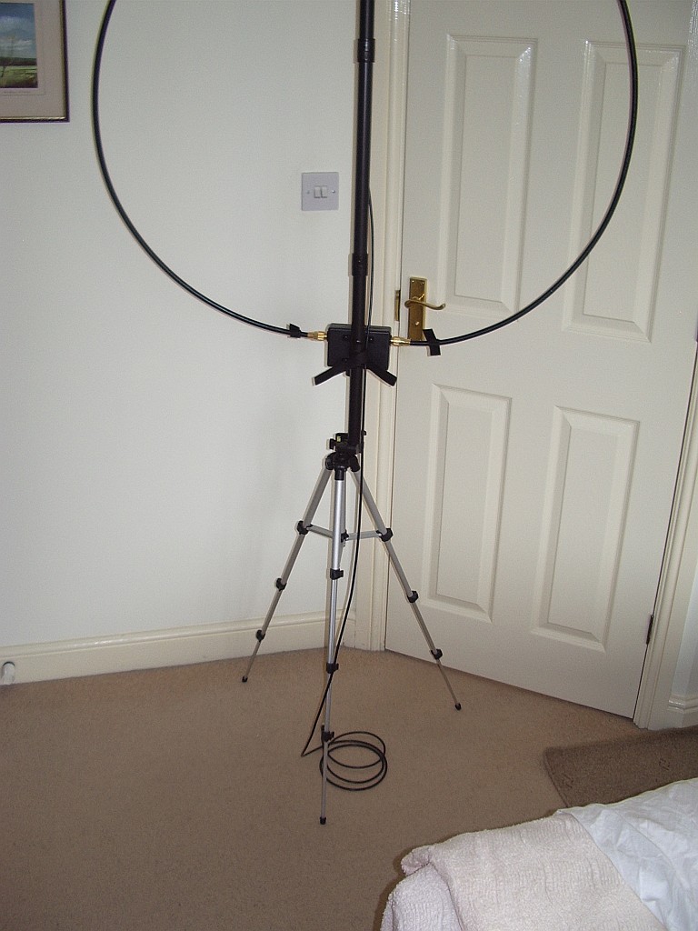
Having got an AlexLoop WalkHam antenna I needed some way of holding it up whilst it was in use. After considering ideas like a guyed mast made from plastic pipe I decided the best solution would be a photographic tripod, if only I could devise a way of mounting the antenna on it.
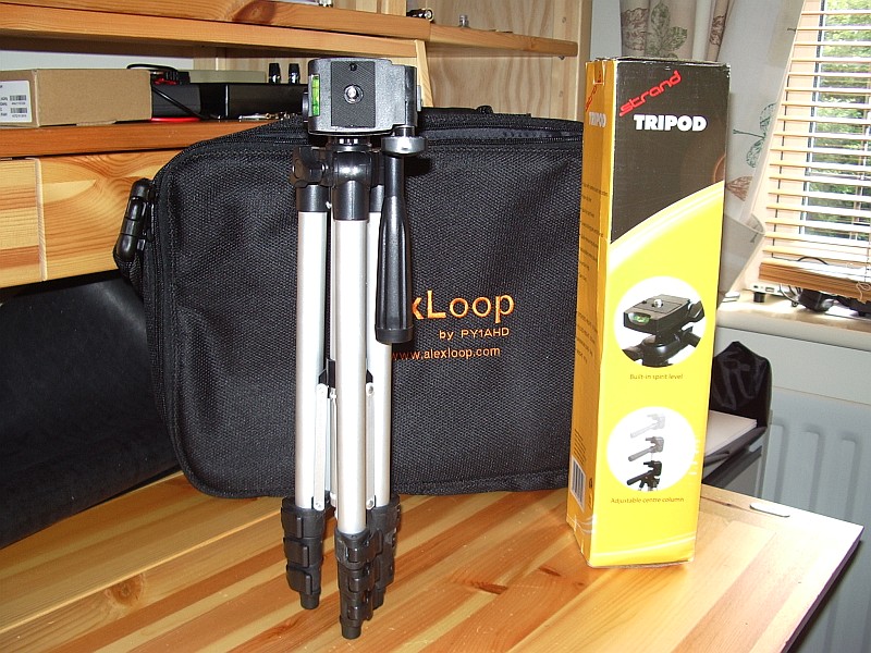
After scouring eBay for a suitable tripod I came across this one from British firm Strand Europe. Unfortunately this won’t be much help if you’re not in Britain as the seller will only post to the United Kingdom.
The tripod is short enough when collapsed to fit inside the WalkHam carrying case – the stumbling block for most of the ones I looked at which were just a bit too long. What’s more, the panning handle can be secured in the vertical position and fits inside the WalkHam’s mounting pole like it was made for it! So no modifications are needed and you can still use the tripod for photography if you want.
The same day that the tripod arrived I received an email from Alex giving details of his own tripod recommendation. He wrote:
“The perfect tripod is the VIVITAR VIV-VPT-1250. It is a 50” unit and the lightest and most inexpensive VIVITAR unit that can be found for less than U$ 10.00. The secret is take off the camera head with a Phillips screwdriver and leave the aluminum tube on the top. It must be marked with a pencil at 4 inches (12 cms): that is the maximum extension that can be used to introduce something to avoid any pressure on the antenna elements. Without the camera head the tripod can be collapsed and carried inside the antenna bag.”
I couldn’t find the Vivitar for as little as $10 in the UK so I’m content with my purchase. My only reservation is that the tripod is much lighter than the antenna (a good point for the person carrying it of course) and might be inclined to blow over if used in much of a breeze. I’ll find out when I manage to try it! I can’t say whether Alex’s recommended model would be any better in that respect.


