Posts Tagged ‘Magnetic Loop’
 AlexLoop teams up with KX3
Just a few days after I wrote that the AlexLoop WalkHam is a great companion for the Elecraft KX3 and here is a video by Steve WG0AT showing the combo in action.
5 and 9 using QRP SSB! I can’t wait until I’m fit enough to take the KX3 and loop to the outdoors myself.
Looping the loop
Whenever I have taken a rig to operate in the Great Outdoors using a wire antenna I have often been disappointed. This is probably due to my use of inadequate antennas – Miracle Whips and the like. When I have tried wire I usually fail to get it up high enough. Usually when hurling a rock attached to a string into the trees, the rock rebounds off a branch and narrowly avoids hitting me on the head. If I do manage to get it up high the rock irremovably entwines itself with a branch just out of reach. There has to be a better way!
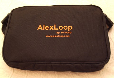 |
| AlexLoop WalkHam carrying case |
I have long been an enthusiast for magnetic loop antennas and have often wished I could use one as a portable antenna. My Wonder Loop was an attempt to make such an antenna, but it was less portable than transportable (by car) and has seen more use as a spare antenna from inside the shack.
I looked longingly at the WalkHam made by Alex PY1AHD and wished I could make a portable loop as neat and compact as that. If I had to make it myself it might never get done so I decided to bite the bullet and buy one of Alex’s ready-made loops.
There are two versions of the AlexLoop. One is a kit using copper tube for the radiating element and costs $199 US. The other version, called the WalkHam, uses stout coaxial cable for the main loop and comes ready built in its own custom made carrying case similar to a laptop case. The price of the AlexLoop WalkHam is $299 US. Shipping to the UK by express courier to the UK is a further $82 US. The total cost to me using PayPal was just over £250 at the present exchange rate.
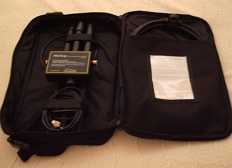 |
| AlexLoop WalkHam in its case |
The WalkHam is well made with gold plated connectors for the loop element. It is easy to assemble, though not so easy to pack away unless you have a photo to show how the parts go back! The mast is made of black plastic tubing and is in three push-together sections. Once assembled the antenna may be used whilst held aloft – hence the name. Most users will probably prefer some sort of mast.
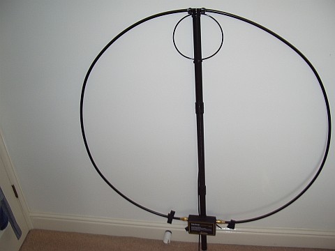 |
| The AlexLoop WalkHam ready for use. |
The loop is 1 metre in diameter and tuned using an air spaced variable capacitor with a 3:1 reduction drive giving a 4 : 1 tuning range: 10m – 40m. Most magnetic loops including home-made ones only manage a tuning range of 3:1: 10m – 30m or 15m – 40m. My MFJ magnetic loop is the 40m – 15m version as it was bought during the last solar minimum when 12m and 10m were not much use!
The coupling loop has a diameter of about 20cm. The maximum power handling is 20 watts PEP, 10 watts continuous wave, making the WalkHam perfect for use with QRP radios like the FT-817 or Elecraft’s new KX3!
Tuning as expected of a magnetic loop is extremely sharp but I noticed little or no hand-capacitance effect. With a little practice the loop can be tuned by peaking for maximum noise in the receiver. If the SWR isn’t low enough then the tuning may be touched up using transmit and the rig’s built-in SWR meter if it has one (both the FT-817 and KX3 do!) If not, a simple SWR indicator as I used in my Wonder Loop would be a big help.
Subjectively the AlexLoop seems to work as well as my MFJ magnetic loop in the attic, which itself is comparable to a full-size dipole. There are not many portable antennas that would beat the AlexLoop WalkHam for performance, unless you are able to erect a couple of 40-foot masts!
One thing that would improve the package would be a way of erecting the antenna so that it will stand on its own. I think my arm would soon get tired holding the WalkHam aloft! Possibly a short guyed mast made of sections of electrical conduit would do the job: magnetic loops don’t need to be far above ground in order to work. Some users are reportedly using photographic tripods so I’ll probably investigate that in due course.
DIY Magnetic Loop Antenna – Part 3
Well, I finally have had time to sit down and put together part three of the DIY Magnetic Loop Antenna, sorry it has taken so long!
This post will cover building and coupling the loop to your transceiver. After reading through posts one and two you should have a good idea of the parts you’ll use and the physical dimensions of the main loop.
DIY Magnetic Loop Antenna – Part 1
DIY Magnetic Loop Antenna – Part 2
Most magnetic loops have the capacitor at the top of the main loop and the gamma match or matching loop at the bottom, this arrangement avoids running the feed-line through the center of the antenna.
You can assemble the main loop from continuous copper tube or from eight straight sections and 45 degree joiners. Make sure you have a blow torch or propane torch to solder the joints as you’ll need more heat than a soldering iron can supply. Whichever way you decide to build the main loop make sure that all joints are soldered or clamped as securely as possible, you want the lowest resistance possible to avoid your output power turning into heat. Other materials can be used for the main loop such as aluminium or low loss coax but copper pipe is easy to work, has low resistivity and available from just about every hardware store.
To construct the frame of the antenna you can use PVC pipe. It is a cheap and relatively sturdy building material and is available in a range of thicknesses, just about any hardware store will stock a wide selection of fittings. It insulates well and can be glued once you are sure your project is in its final form.
Once the main loop is constructed you’ll need to connect your capacitor to the two ends of the pipe at the top of the loop. Depending on the capacitor you may want to solder tags to the ends of the loop so they will be easier to attach. Copper pipe is a great conductor of heat and takes a lot to heat up and solder while it is not advisable to apply the same amount of heat to your capacitor.
It is also a good idea to attach the capacitor to a solid support so that the connections are not under strain.
The main loop and the capacitor forms the resonant circuit of the magnetic loop antenna.

To couple the main loop to your transceiver and match the expected 50 Ohms impedance you can use one of two methods. Probably the easiest is to use is a loop of insulated wire 1/5 the circumference of the main loop. The smaller loop is placed at the bottom of the main loop and can be shifted around to provide the best match. If you have an antenna analyzer you’ll be able to set it to the desired frequency, tune the variable capacitor for resonance and then move the small matching loop around till you have achieved close to 1:1 SWR. If you don’t have an antenna analyzer you can tune the capacitor for the greatest received noise and then on low power tweak the capacitor and move the coupling loop around for best SWR. Do NOT touch the loop while it is transmitting, use a wood or plastic rod to make adjustments as there are high voltages and intense RF fields near the loop.
An alternative to the coupling loop is the gamma match. The shield of the coax feed cable is connected to the base of the main loop while the inner conductor is connected to a point approximately 1/5 of the circumference around the loop. Its a good idea to use stiff wire (large gauge) for the gamma match as it can be critical of the position and orientation and once you have it in the right position you won’t want to move it again.
It would be preferable to have the ability to remotely tune the loop. A motor with a reduction gear could be used to move the variable capacitor but because the point of resonance is very narrow there should be a way of slowing the motor down. A simple control circuit using variable pulse width modulation could be used to slow the motor down while still retaining enough torque to move the capacitor. Whatever method is used to move the capacitor it should be well insulated from the other components of the antenna. Several thousand volts are generated on the MLA and care should be taken to ensure they don’t find their way onto control leads and back into the shack. Control leads should also be wrapped around toriod inductors as they leave the near field of the antenna to reduce the possibility of RF travelling along them.
With a SWR bridge and microcontroller you could build a fully automatic tuner that swept through the range of the tuning capacitor when the SWR rose above a defined limit indicating that the transmit frequency had changed.
With a little creativity and knowledge you could have an impressive MLA the equal of multi-thousand dollar military style units.
Hopefully this has given you some ideas for constructing your own loop antenna. Regardless of if you go top-of-the-line and buy a vacuum variable or build for economy and QRP you’ll have a compact, useful and unique antenna.
DIY Magnetic Loop Antenna – Part 2
Part 1 of the DIY Magnetic Loop Antenna covered mostly theory and materials so now its time to move on to designing the magnetic loop antenna (MLA).
If you have priced a commercially made MLA you’ll see prices start at $400 and keep going up, and up. If they cost so much you would think they must be difficult to build or use expensive parts, right? Well, it is certainly possible to spend more and get a higher quality MLA but a low cost MLA will still work very well.
For the purposes of this article we’ll assume that you want to build a loop to cover the 20-10M bands. I’ll run through the calculations required to build the MLA.
The required information for the MLA calculator is:
- Length of the loop
- The conductor diameter
- Frequency/s of operation
- Input power to the antenna
- We don’t really know the best length of the loop at the moment so I’ll pick 9 feet circumference as a starting point (It’ll still fit in the trunk of my car)
- Since we seem to be having better luck with sunspots now I’d like to try 10M so we’ll start with 29 Mhz as the highest frequency we’ll use.
- I have some copper pipe left over from an ice-maker install, it is 1/4 (0.25) inch in diameter.
- Input power to the loop will be 100W.
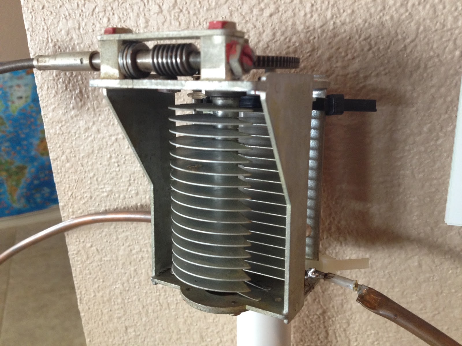
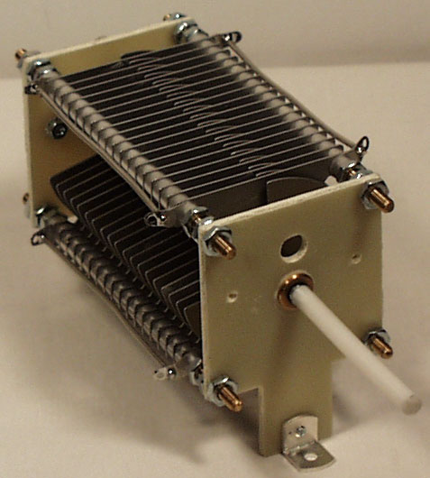
 A peak voltage of 5181V will require a minimum spacing of 1.7 mm (peak voltage / breakdown voltage per mm) between the closest conductors in the capacitor. That would rule out an old air spaced variable capacitor from a vacuum tube radio but you could still use a wide spaced variable capacitor from an antenna matching unit or transmitter. A vacuum variable capacitor would be great (watch the minimum capacitance) or a home-made capacitor would also be fine provided you checked the breakdown voltage of the insulating material.
 DIY Magnetic Loop Antenna – Part 1
Do you live in a neighborhood with a restrictive antenna policy and despair of having a useful HF antenna?
Can you solder or know someone who can?
A magnetic loop antenna may be the answer and they are not as difficult to build as you might think. Like getting on the air for the first time or taking your license exam there is a certain amount of uncertainty when you first approach magnetic loop antennas, there are a few new ideas to grasp. However, thanks to other hams like Steve AA5TB there are tried and tested designs, calculators & building methods that are known to work and that you can follow.
 At the heart of every radio and MLA (Magnetic Loop Antenna) is the resonant circuit. The combination of an inductor (a wire has inductance, but a coil of wire has more) and a capacitor (two conductors separated by an insulator) in a circuit will resonate or ‘ring’ at a certain frequency. Sound vibrations at a certain frequency can cause a piano string to vibrate in sympathy and a vibration of the correct radio frequency will cause a resonant circuit to electrically vibrate in sympathy.
Since there is no such thing as a free lunch, the sacrifice you make with a MLA is that it needs to be re-tuned whenever you change frequency on your transceiver. The frequency range over which it is resonant is very small, typically only a few hundred kilohertz at the most.
The materials you can get your hands on is going to decide the capabilities of your MLA. Ideally you’ll have a loop made from a conductor with very low resistance (usually copper) and a capacitor that can handle high voltages. A variable capacitor is required if you want to use your antenna on multiple frequencies but you can use or make a fixed capacitor if you operate on one frequency, for Eg PSK31.
A MLA calculator like the Excel spreadsheet from Steve AA5TB or this web page from 66pacific.com will help you to decide what size components you’ll need to make your antenna.
The four pieces of information required are:
- What frequency or frequencies do you wish to transmit on?
- How large do you want the loop to be (It should have a circumference less than 10% of the design frequency wavelength, both calculators help you figure this out)
- The diameter of your conductor (Three quarter inch (0.75 inch) copper pipe is a good start)
- How much power you want to use (The voltage across the capacitor is proportional to the input power to the MLA)
 A MLA of a certain circumference will be more or less efficient based on the frequency you transmit at. It is worth changing the loop size in the calculator to get the best efficiency possible in your favorite band.
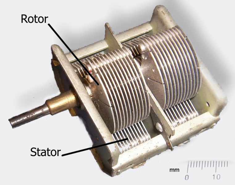
Sivan’s Wonder Loop
It’s always good to hear when something one does or writes inspires somebody else to try it and they are pleased with the outcome. Sivan, 4X6IZ, made a version of my portable Wonder Loop and found that “it works as advertised.” He has put some information and pictures of it and another loop he made on a website. His idea of using polyethylene coated aluminium pipe to make a fixed frequency loop and tuning capacitor is particularly interesting if you always operate close to a particular frequency such as for QRP CW, PSK31 etc. If I had space in my attic for another magnetic loop I could dedicate for HF APRS use I would definitely make one of these.
I’m sure you’ll find it worth reading about Sivan’s magnetic loop antennas.


