Posts Tagged ‘kit’
 One for the Boys (or the Girls!)
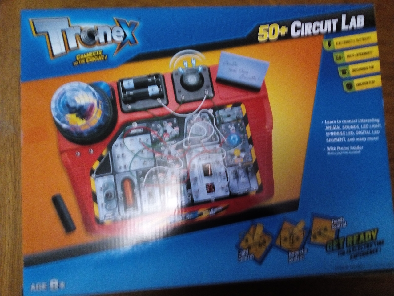
So I was in my local discount store the other day, something caught the corner of my eye, an electronic kit. Tronex 50+ Circuit Lab. Made in, you guess right China! But does similar to what I have mentioned above. Yes it resembles the kits that were once produced in late 70's, where wires were held under springs to connect each component into the circuit.
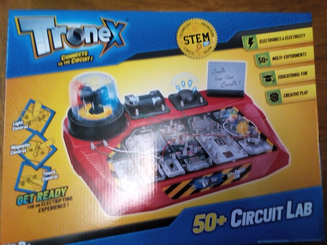
Only having two daughters, one whom is now married, and the other that is now in her latter years of High school, a chance perhaps to encourage her, and get her away from playing with her tablet and computer during the long hours of these dark nights. So I decided to buy one for her Christmas stocking. My wife said you only bought it so you can play with it didn't you? I said no, this is a good educational tool and can be used to encourage, especially with her having to do a science at school.
Not hopeful she will be another Ham in the future, but you never know where it will lead? For overseas readers of my blog I notice there are Tronex kits on ebay of similar content.
I will return to this when she decides to investigate and play, further info here:
https://www.homebargains.co.uk/products/14749-tronex-50-circuit-lab.aspx
It’s ALIVE !
The 1Watter 40m #551 -- Lives
 |
| The 1Watter 40m on it's inaugural QSO |
 |
| Inside the enclosure |
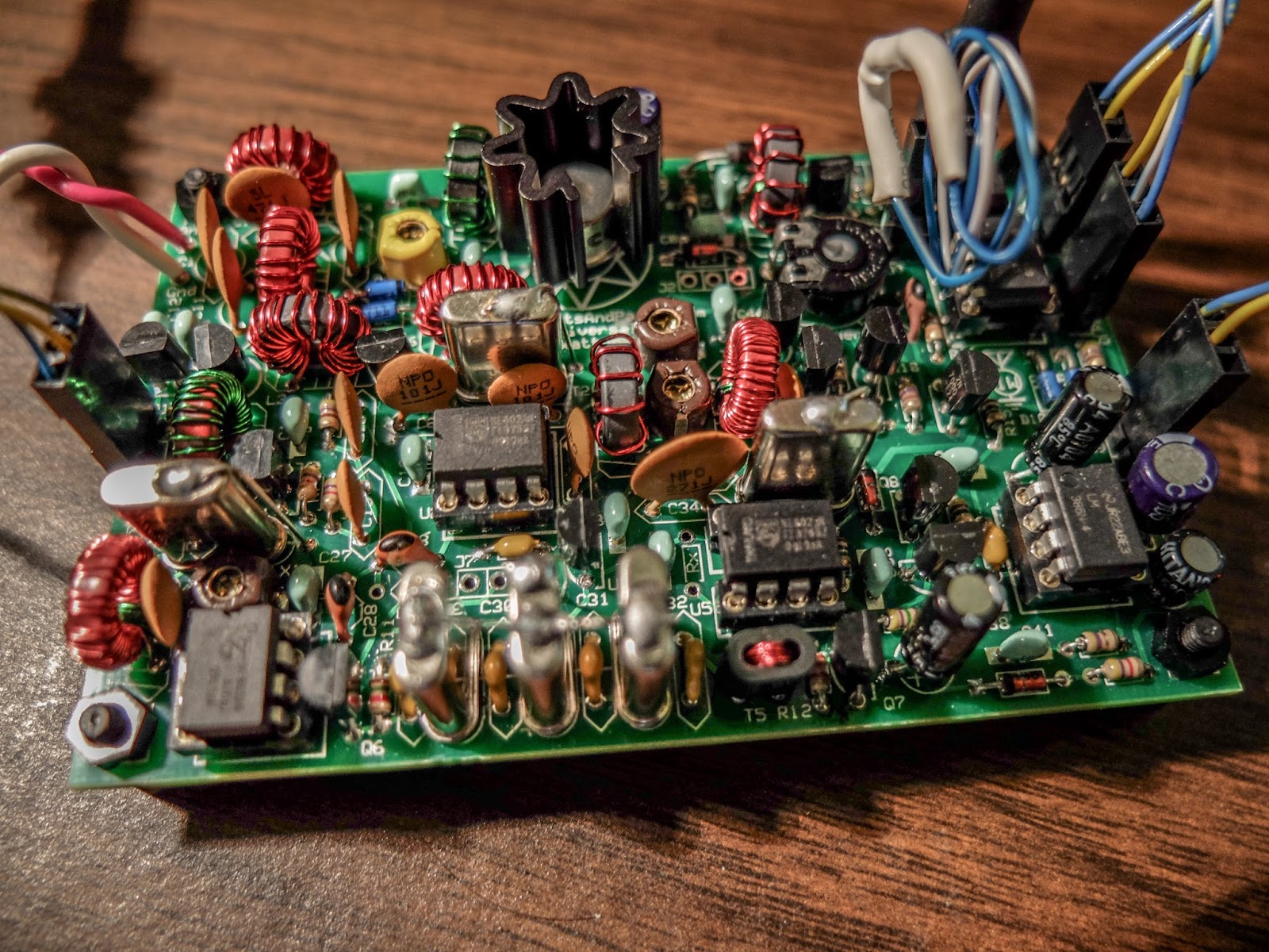
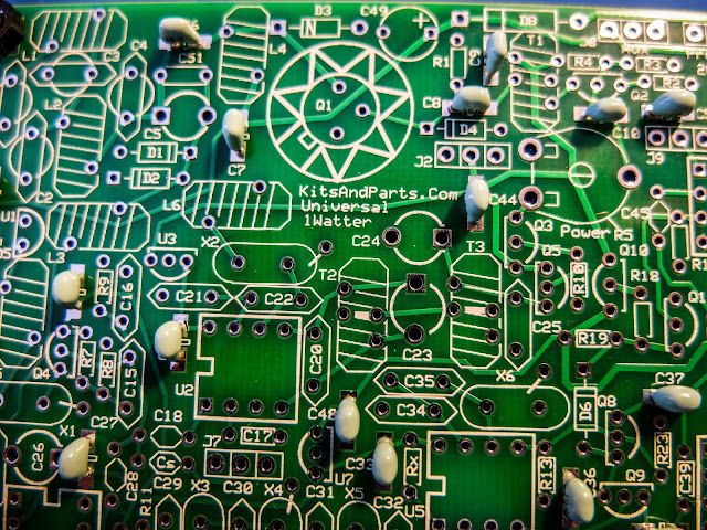
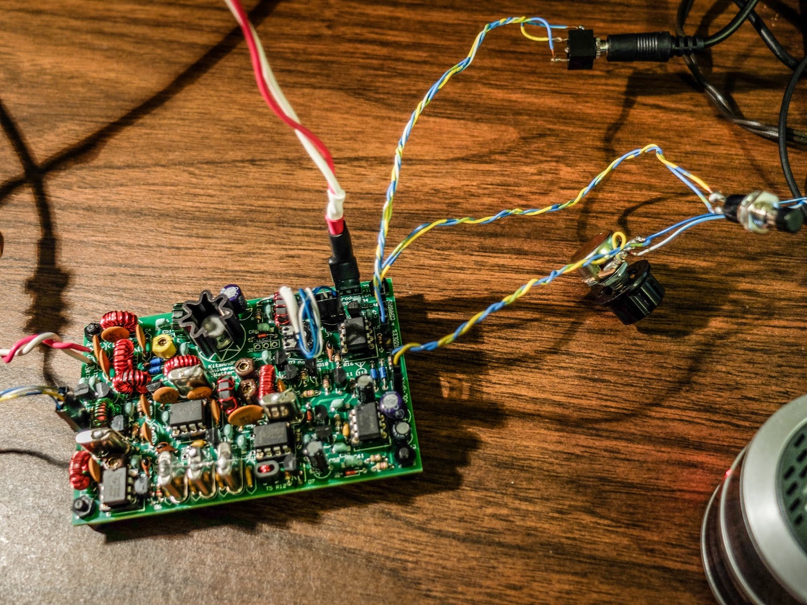
The 1Watter is a kit from kits and parts dot com
- 1 mighty watt of output
- Good selectivity from the 3 crystal filters
- A VCXO tuned frequency range for the 40m band from approximately 7,020 kHz through 7,039 kHz
- A built-in full functioned keyer with provision for adding a speed pot and messages
- Included command button accesses the functions of the electronic keyer
- Natural sounding sidetone (nicer than my Ten-Tec Century/21)
The Build
 |
| SMT and through hole caps are supplied |
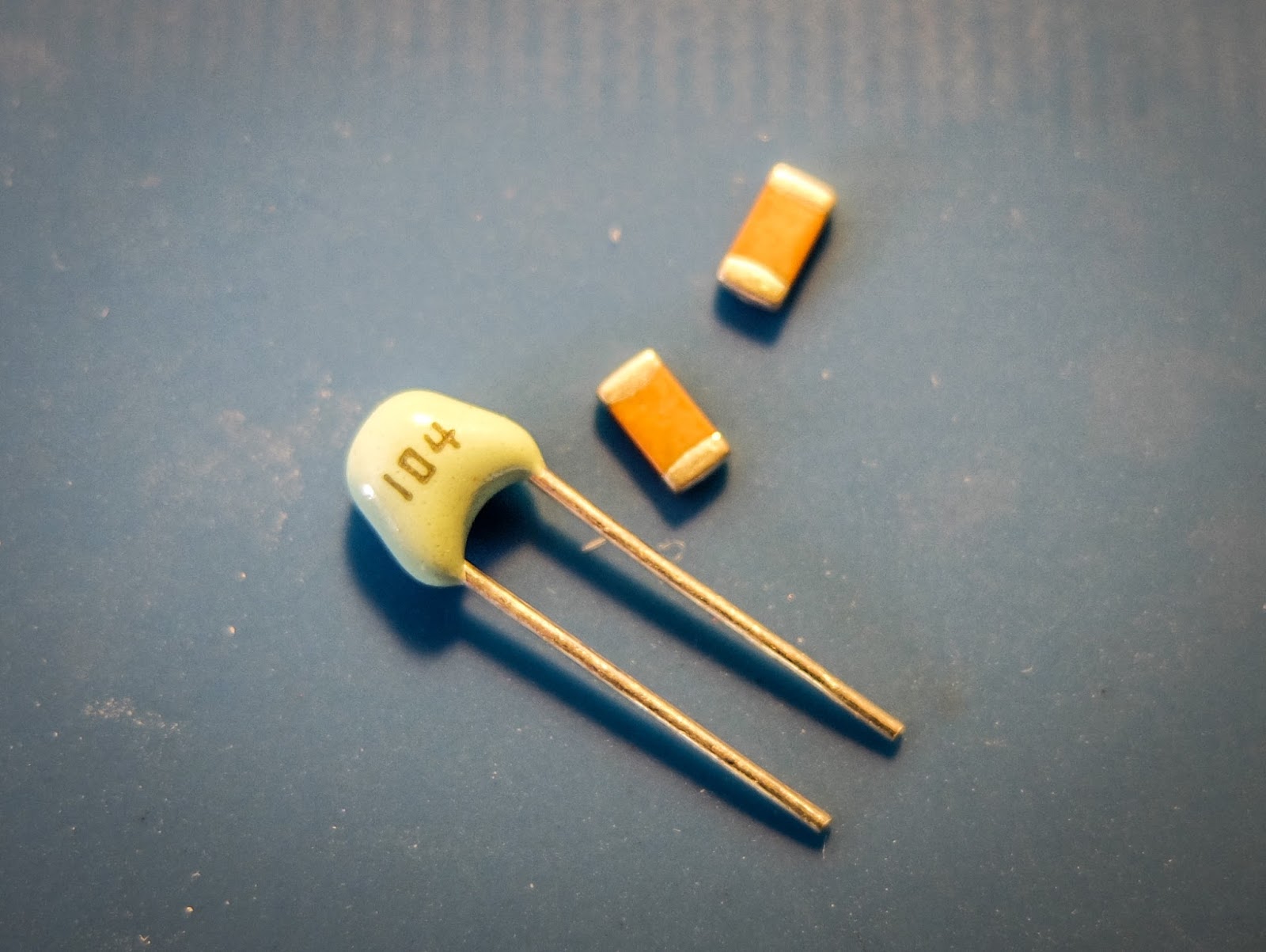
 |
| using through hole capacitors rather than the SMTs |
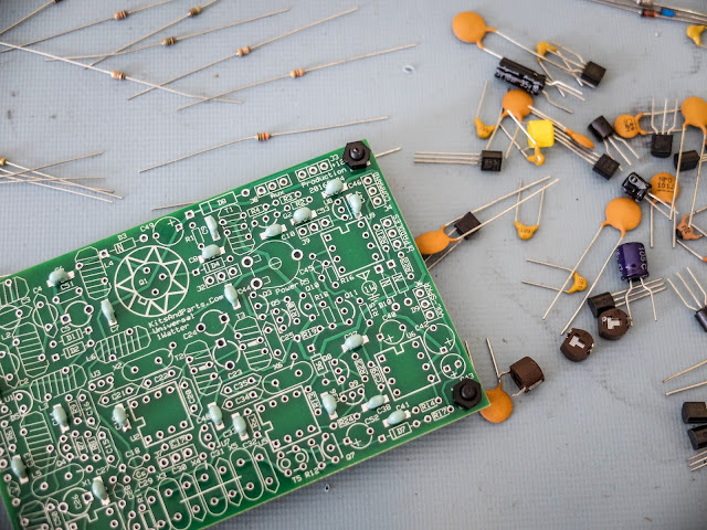 |
| some of the bits and bobs |
 |
| build is progressing |
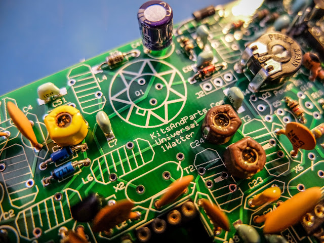
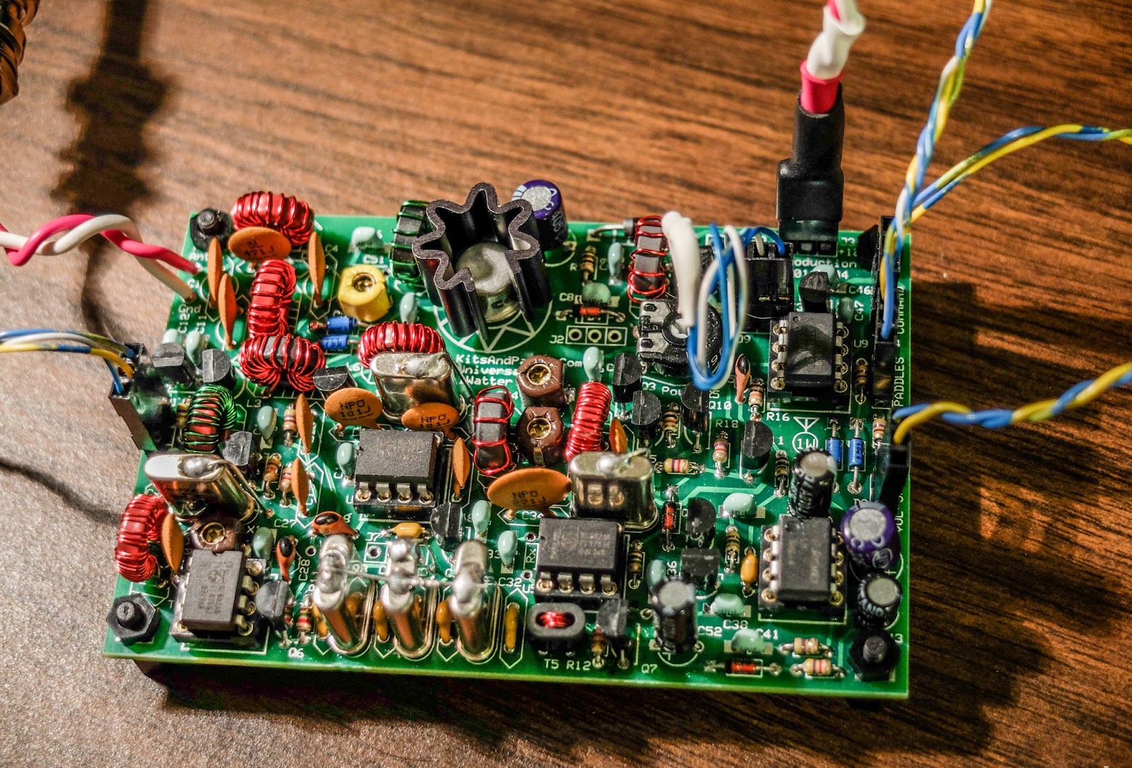
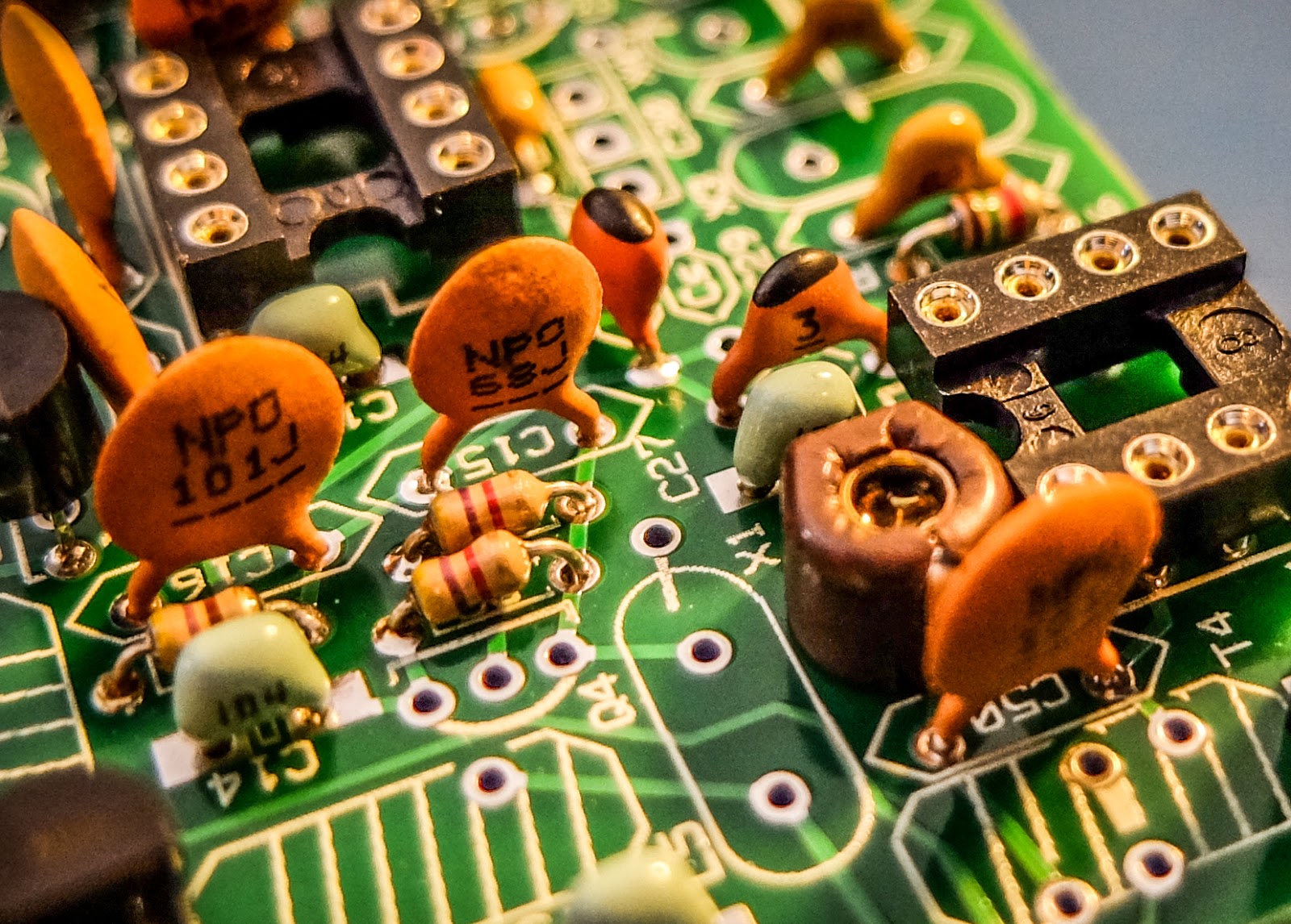 |
| close up |
 |
| XTAL filters give it good selectivity |
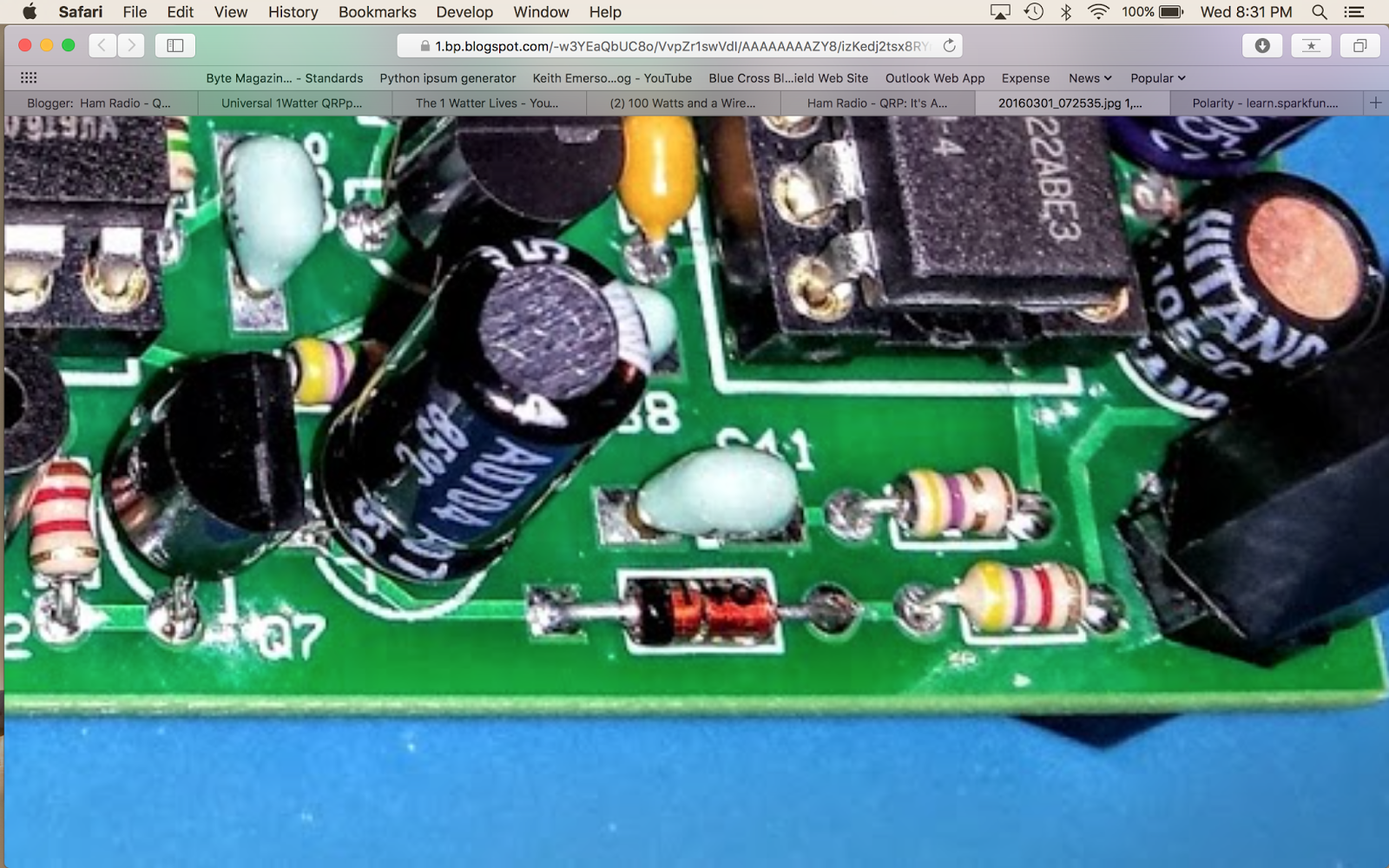
 |
| Everything except the final transistor |
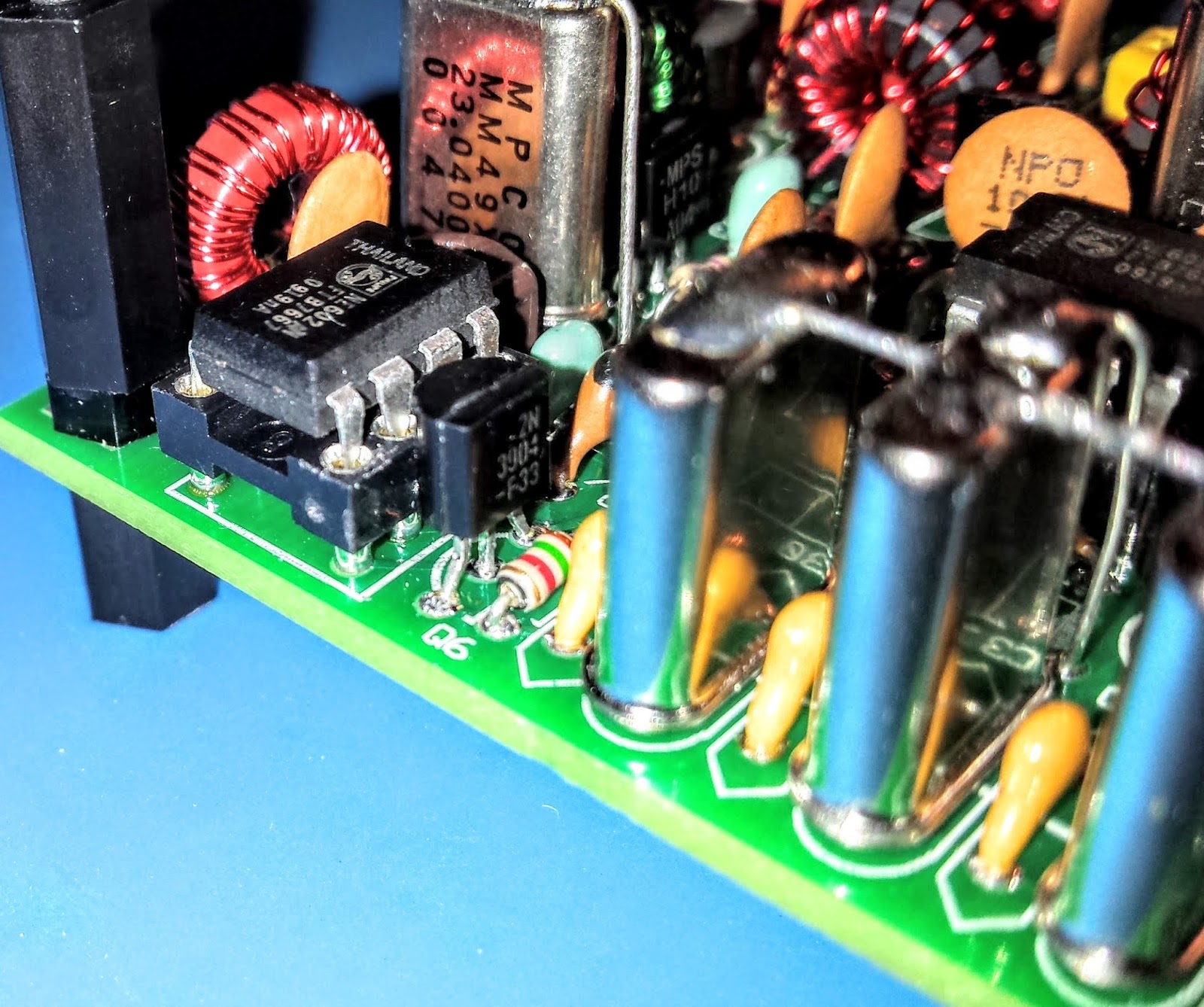
 |
| AGC circuit |
Debugging
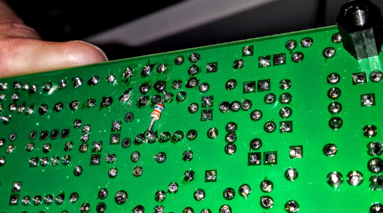 |
| The FIX for all those problems required an extra resistor connected across U5 |
Learning from problems
Being the first person to build a particular version of a kit brings its own set of challenges, especially when you're as new to kit building debugging RF problems as I am. However I'm actually glad the kit didn't work right at the initial build.The process of debugging the board, was a great learning process. I studied the schematics and learned, as best I could, the function of each circuit so that I could better understand how to test it. During the debugging process Diz instructed me that although RF signal generators and scopes are useful you can tell a lot by touching a RF component with an inductive metal object and listening for a buzz or hum from the BFO.
So all-in-all, even though the bug in the board was not due to a error on my part, I'm glad it occurred. I understand more about superhet radio design than I did before and more than if the kit had worked right off the bat.
On the air
 |
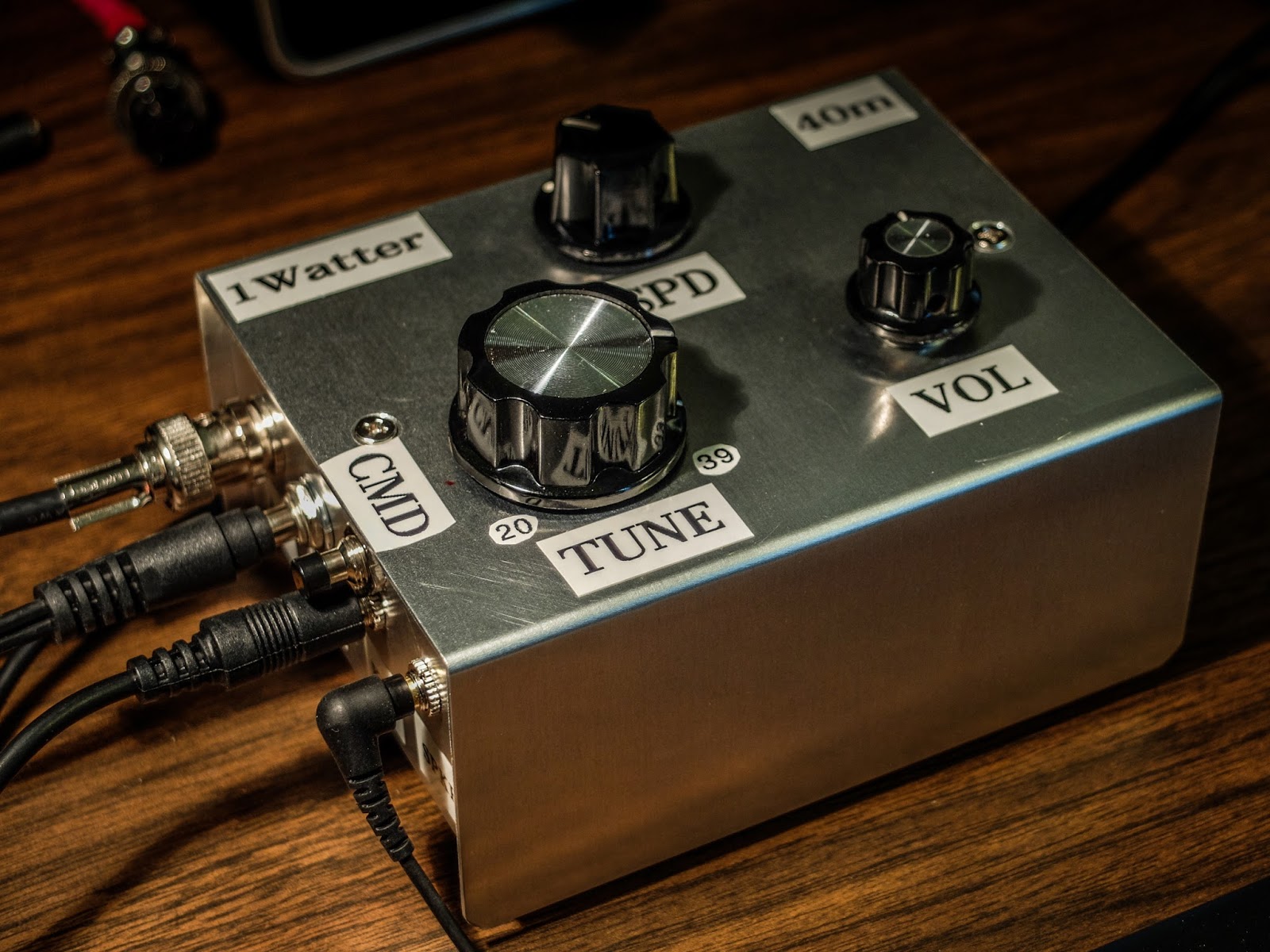
| Frequency control pot on the left |
 |
| Volume control, output jack, cmd pot and paddle input |
For this first on-air excursion I was using it at the default startup 15wpm keyer speed. You can default the speed higher with a different resistor value.
I have a resistor shrink wrapped and connected in-line to the blue-white wire coiling above the radio connecting to the speed pot terminal. In essence fixing the speed at 15wpm until I add the speed pot.
 |
| Ready to transmit |
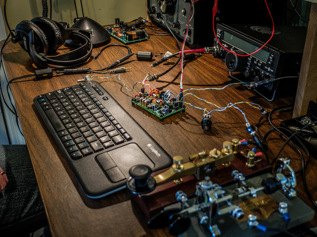 |
| On the air... I was using my paddle out of the photo to the right of the Bug |
First On Air QSO
Summary
Just imagine. This little $50 single band kit has good selectivity, a nice built-in keyer with a natural sounding sidetone, and lest we forget... You get a MIGHTY 1 WATT of OUTPUT. What more could a QRP ham need.
UPDATE: 04/01/2016
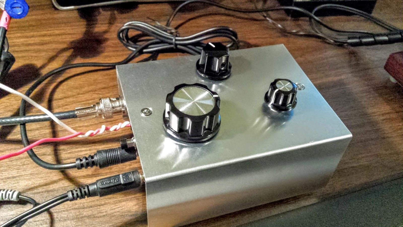 |
| !Watter installed in a case |
UPDATE: 04/05/2016
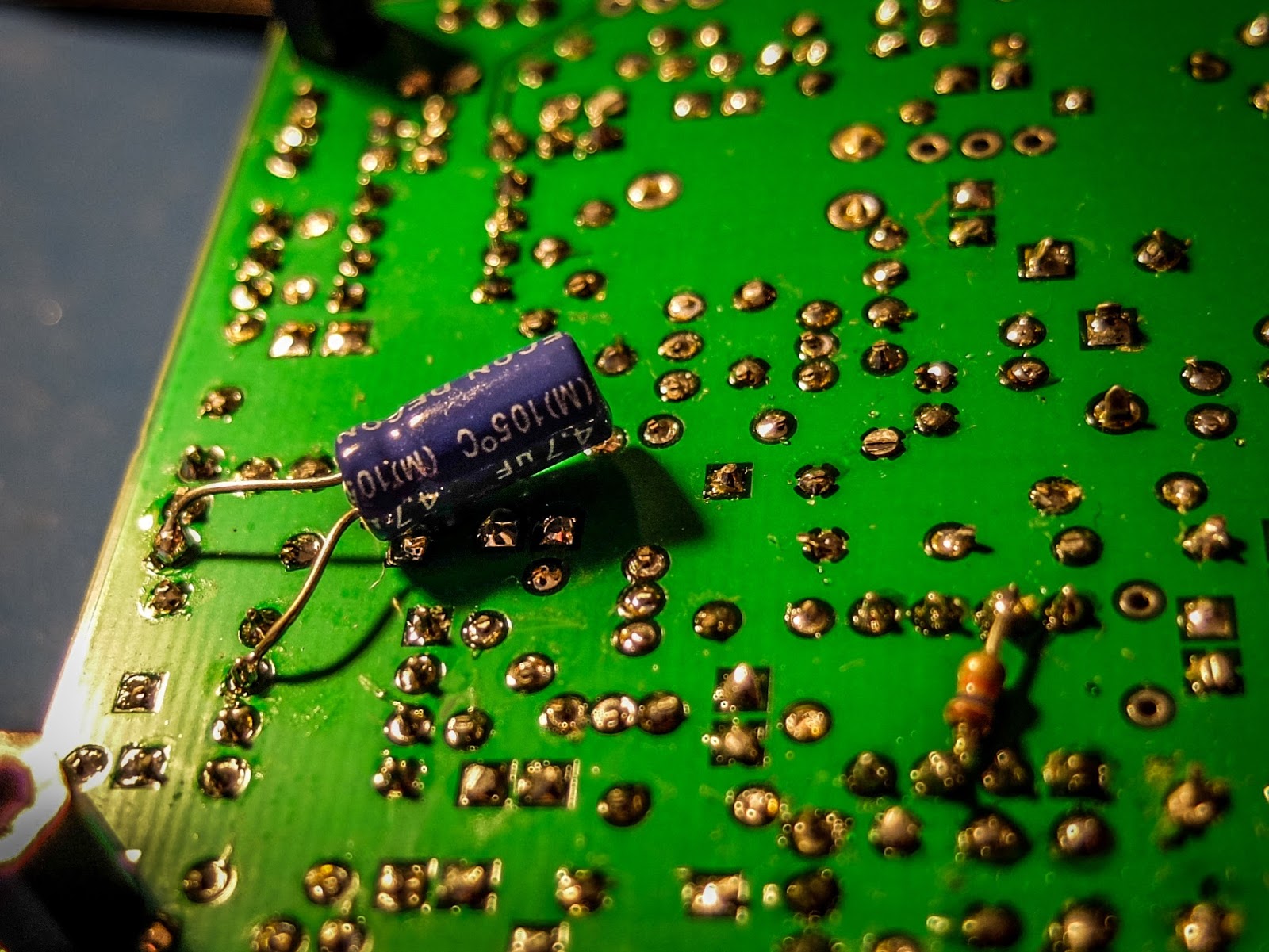 |
| cap fix for LM386 oscillations |
 |
| 1Watter in enclosure with all the proper connectors for the case |
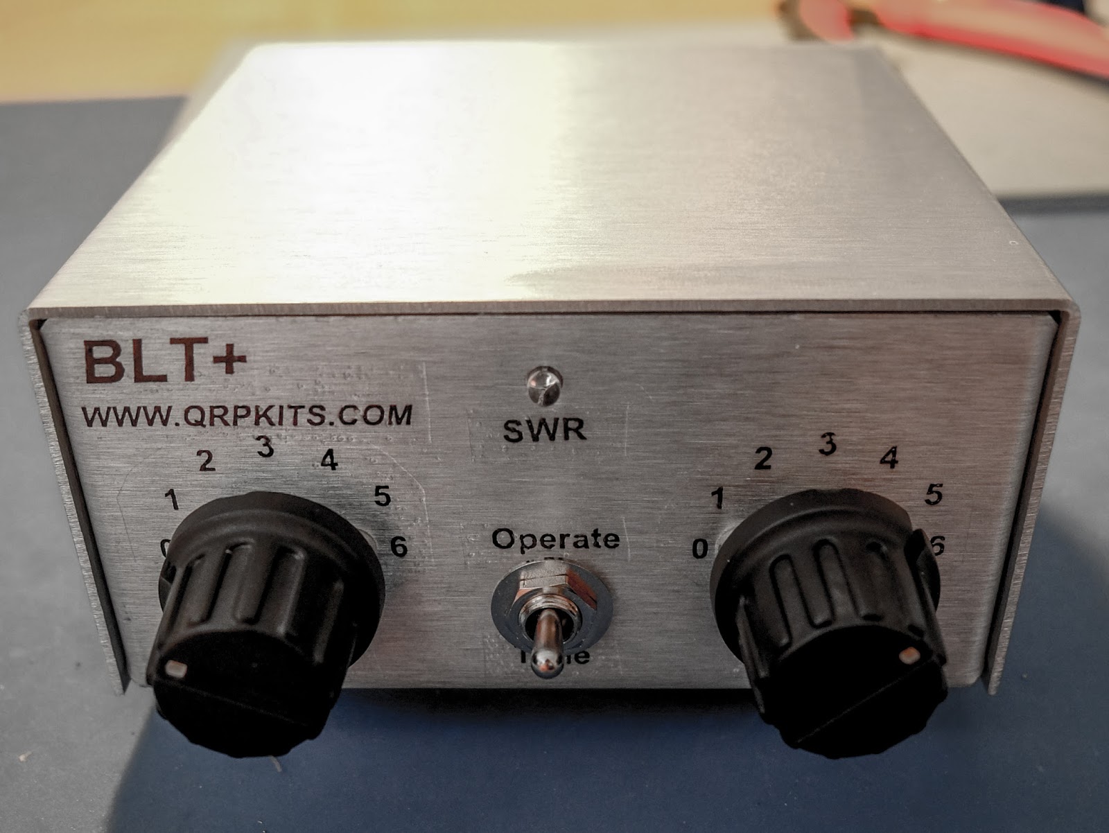
I will have a BLT please
The BLT-Plus Balanced line QRP tuner
I was looking for a QRP tuner for the 1Watter 40m transceiver I am building that would work with both balanced feedline antennas as well as coax feedline. The traditional Z-Match tuner is quite efficient at tuning balanced line antennas and the built-in SWR bridge gives you an all-in-one tuner and SWR indicator without having to take a separate SWR meter along with its inherent mess of cabling a separate SWR meter. The BLT in the name stands for "Balanced Line Tuner".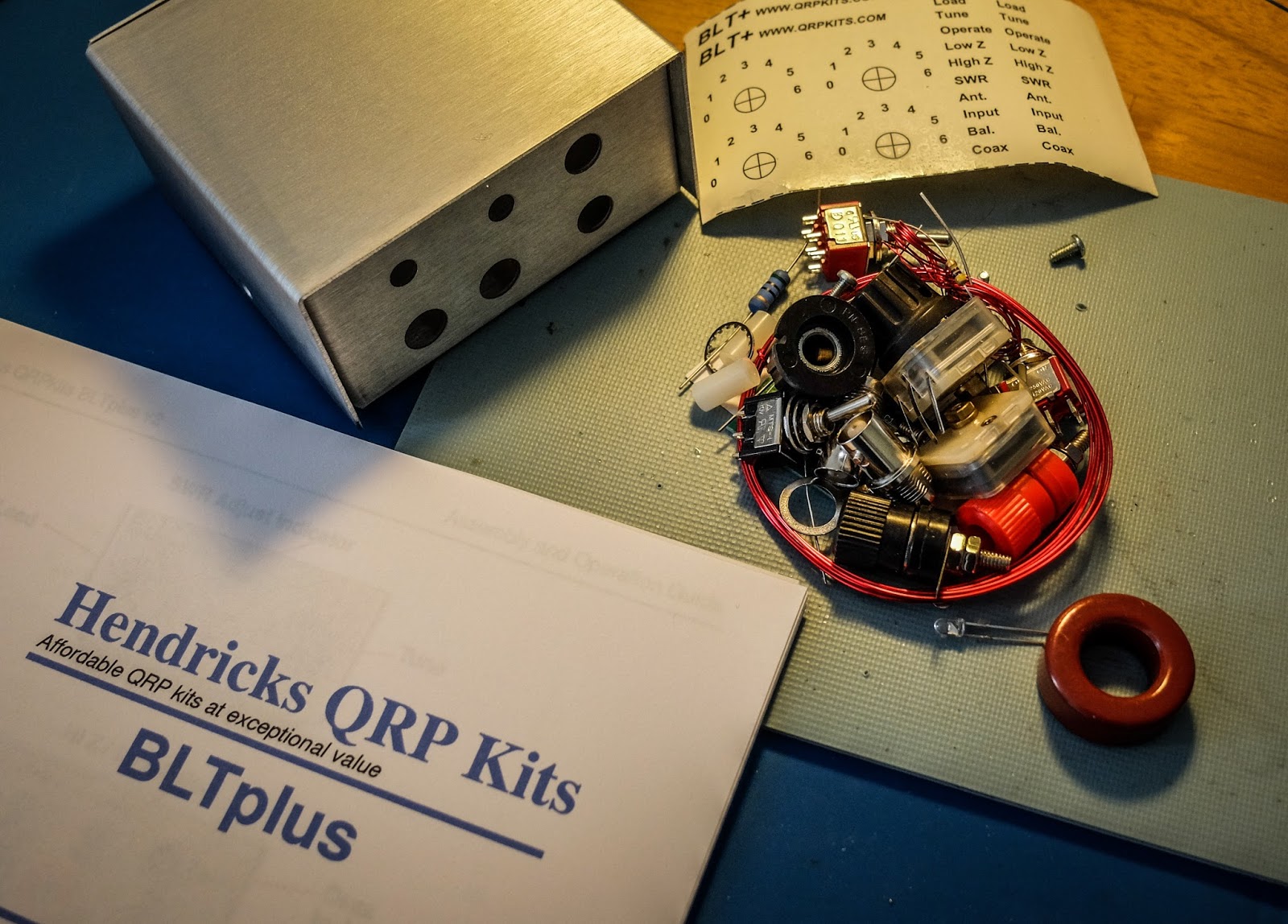 |
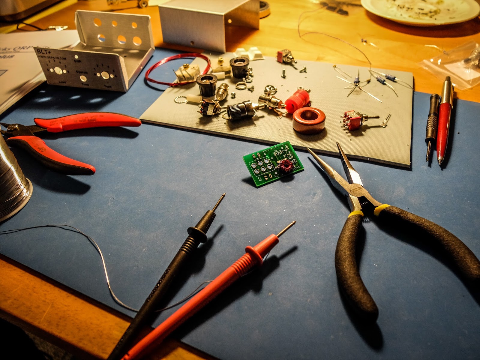
| The Kit as it comes out of the bag |
Why use a z-match ?
- Matches balanced loads without the use of lossy baluns.
- Being a parallel resonant circuit, the Z-match can provide some band-pass filtering for your receiver and harmonic attenuation for your transmitter.
- A well-designed Z-match tuner has a high Q and is more efficient (less lossy) than other types of tuners.
- The fixed inductor simplifies construction (no taps or rollers needed).
The secret sauce
Built in SWR indicator
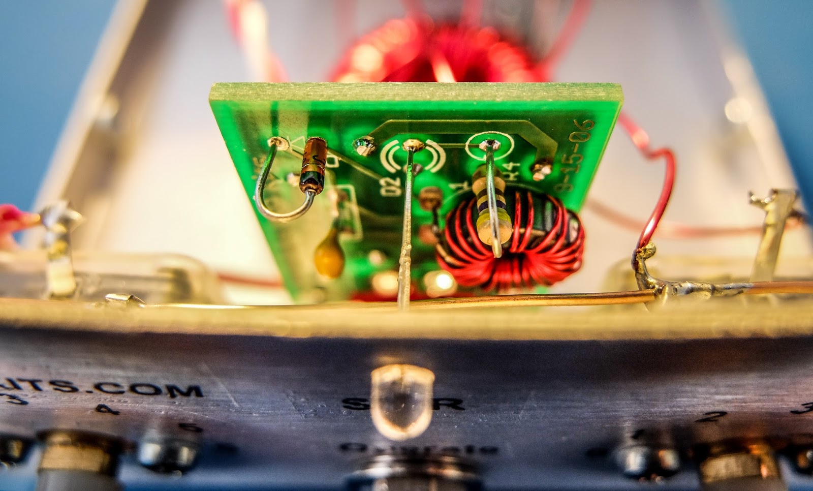 |
| SWR bridge with LED indicator |
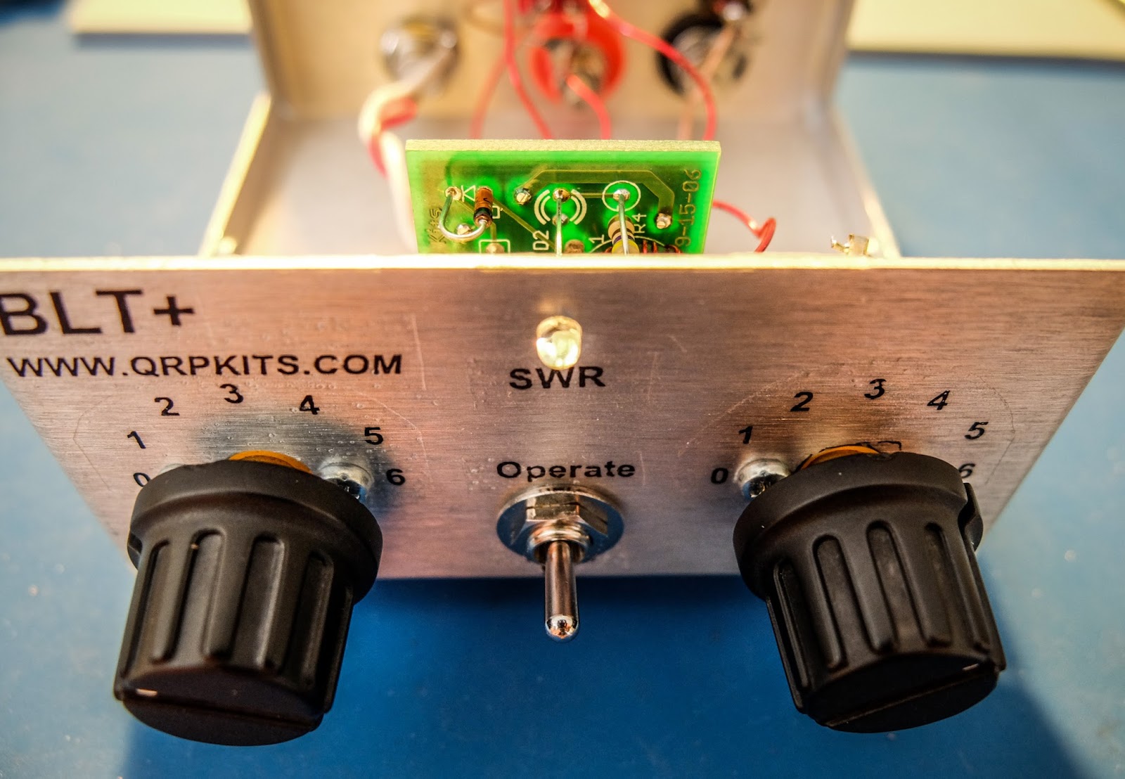 |
| Switch to Tune to present a low SWR to the transmitter while matching, switch to Operate when finished |
Building
- The kit is provided with really nice water slide decals that give it a commercial look (if you don't ruin them like I did). The instructions recommend applying a clear coat to the decals after they are applied. I used a Krylon matte finish clear coat which indicated it was fine for metals and plastics but it partially melted the decals and caused them to bubble. I'd suggest testing whatever you are going to clear coat them with first.
- Don't over tighten the plastic tuner shafts or you won't be able to slide the knobs on (yes I did).
- The binding posts have little plastic spacers that separate and it isn't obvious. If you install them and wonder how they don't ground themselves (like I did) you've done it wrong and will have to go back after it's together and try to remove them with all the wiring in place.
- The bolts for the binding posts are very soft metal and the nuts can strip them if you apply too much force (yep I did that too).
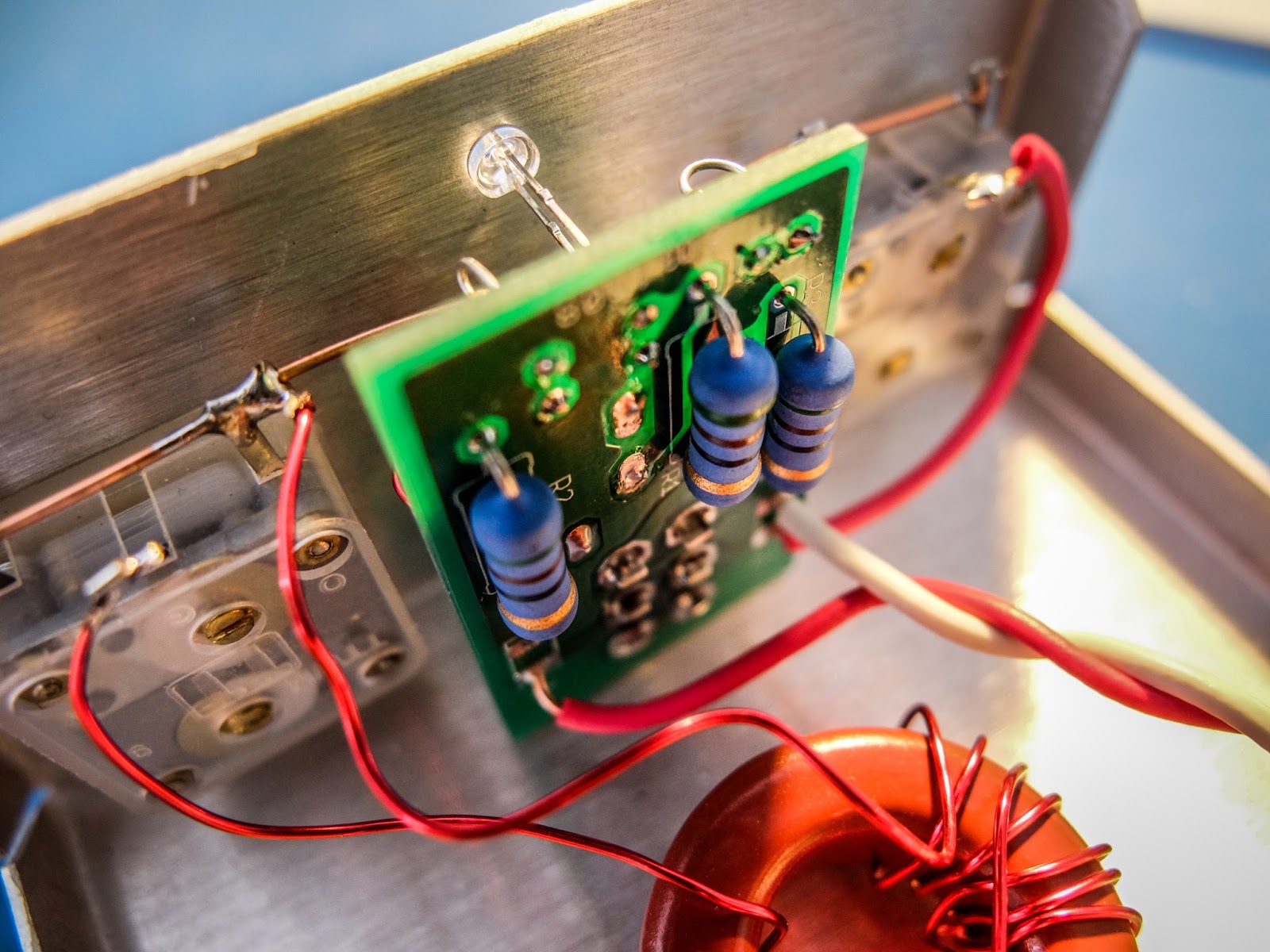
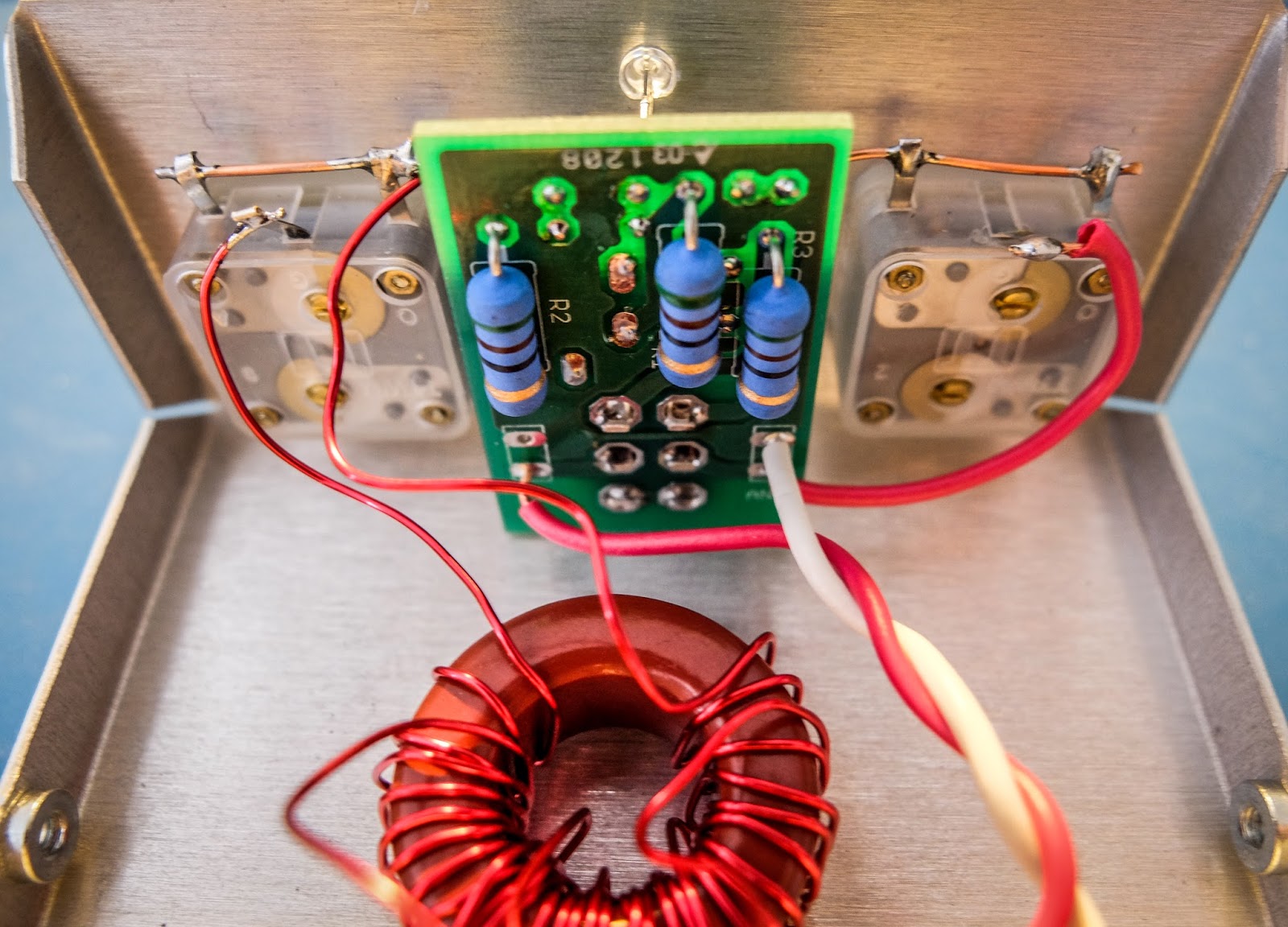
- The main toroid has three sets of windings and they overlap. Pay attention to the instructions about winding them all in the same manner (clockwise or counter clockwise) or you will have to rewind them (yep, I did that too).
- The 3 windings on the main toroid overlap so you won't be able to go back and verify your turns when doing the 2nd and 3rd winding so count carefully (ask me how I know).
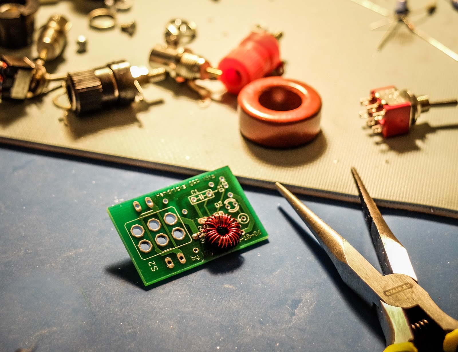
- Temporarily attach the SWR bridge to the front panel to get the spacing correct to solder the LED leads.
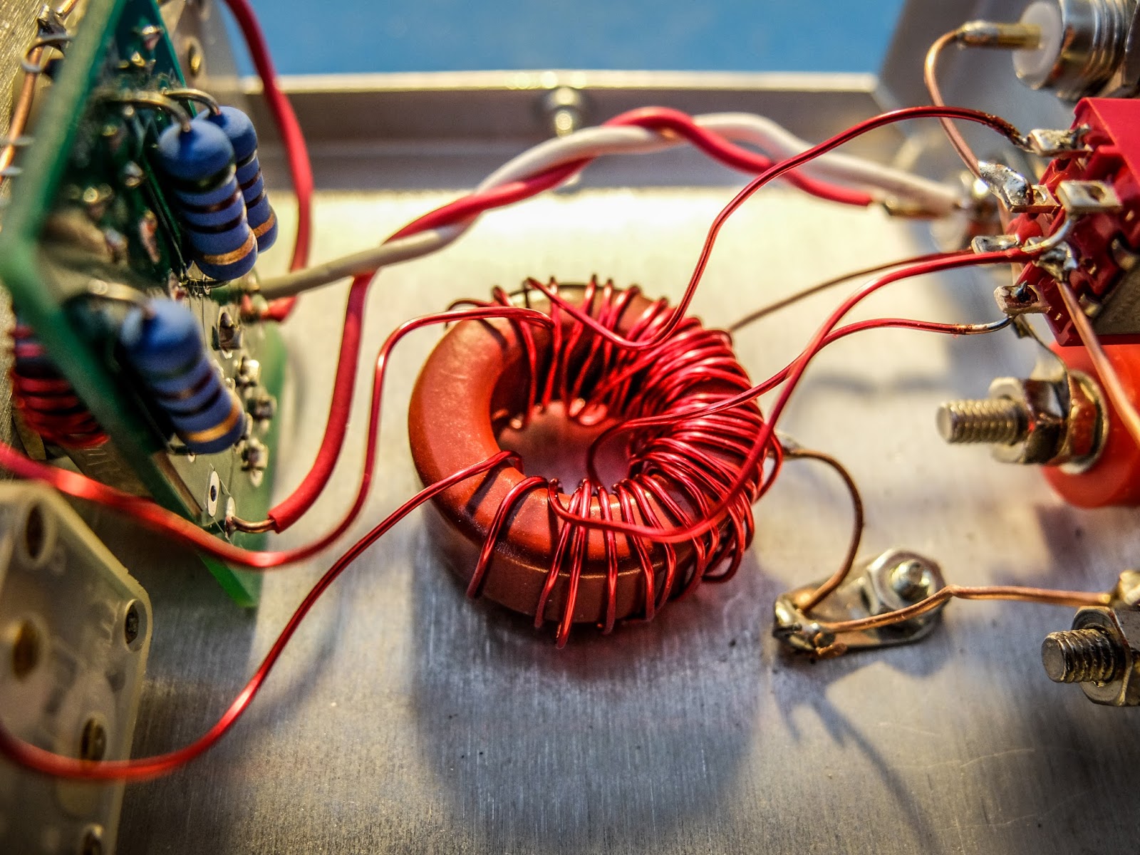 |
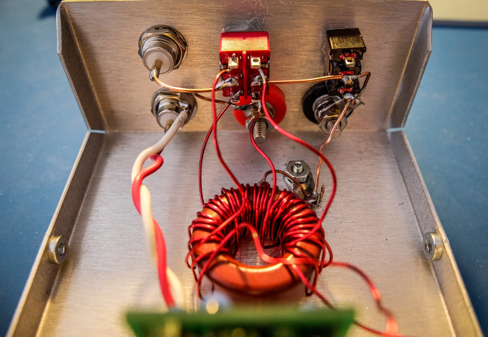
| My messy toroid winding... but it's working fine |
Operation
- Connect your transmitter and antenna.
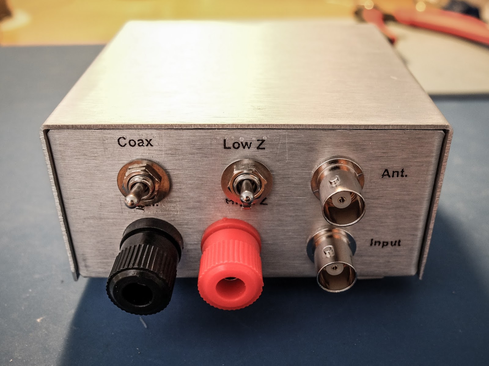
- Choose the appropriate switch in the back for coax or balanced line antenna (Up for coax, Down for balanced line).
- Start with the inductance switch on the back set to low-impedance (Low-Z) because it is the most efficient. It uses the 6 turn secondary rather than the 12.
- Switch the front switch to "Tune"
- Key the transmitter and be sure you are using 5 watts or less
- Turn the "Load" knob first until you see a dimming of the LED then the "Tune" knob to make it go out completely
- The knobs interact so you'll need to go back and forth between them to achieve best match
- If you can't get a good match switch the inductance switch on the back to "High Z" and try again
- Don't apply power too long at a time during tune because the 50 Ohm resistors are heating up in there during the Tune process
- When the LED goes out or gets very dim you have a very good match. Switch to "Operate" and enjoy a well matched antenna
Photos
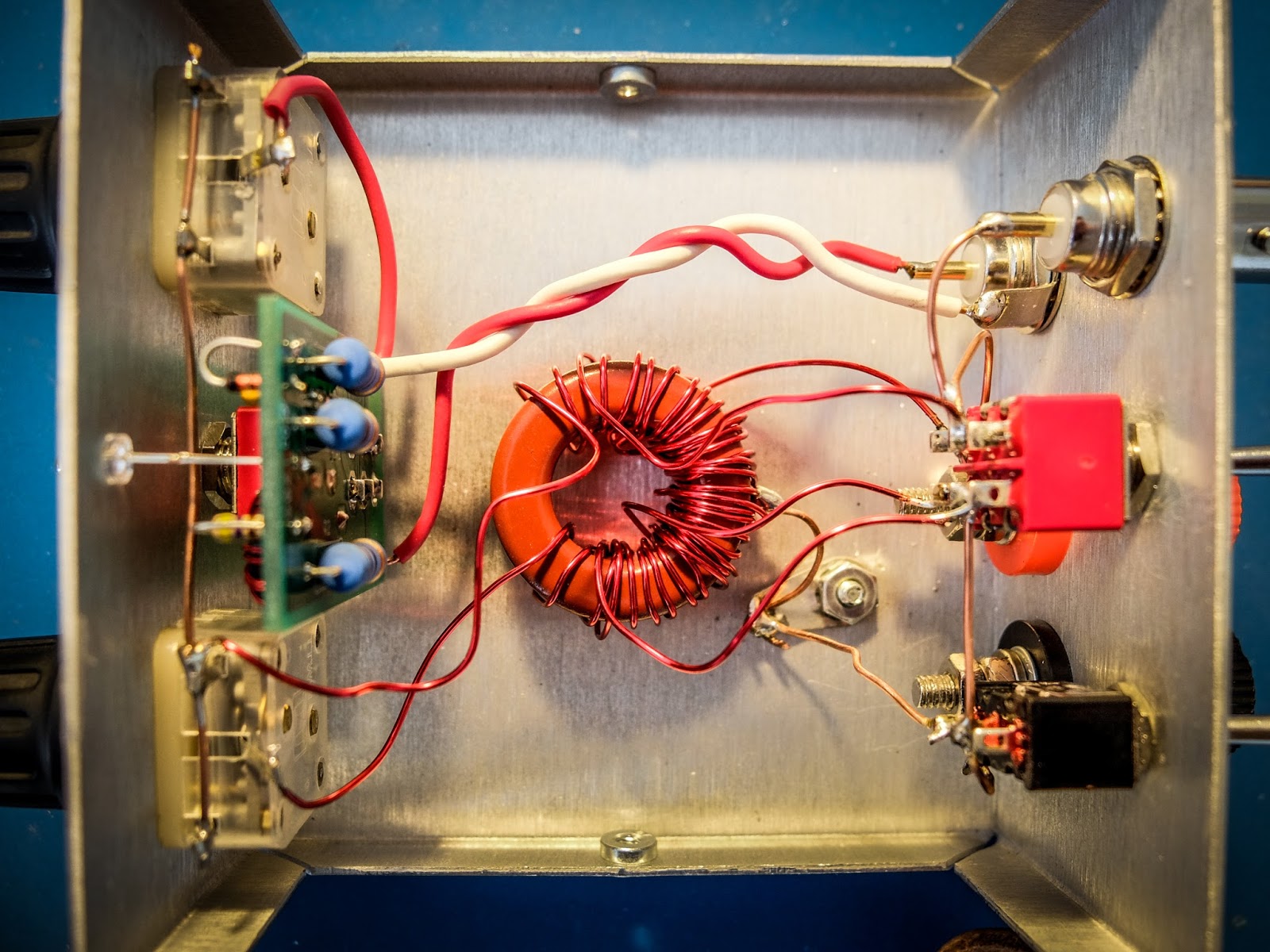 |
| Result of having to rewind the secondaries made it messier than I'd like |
Dimensions
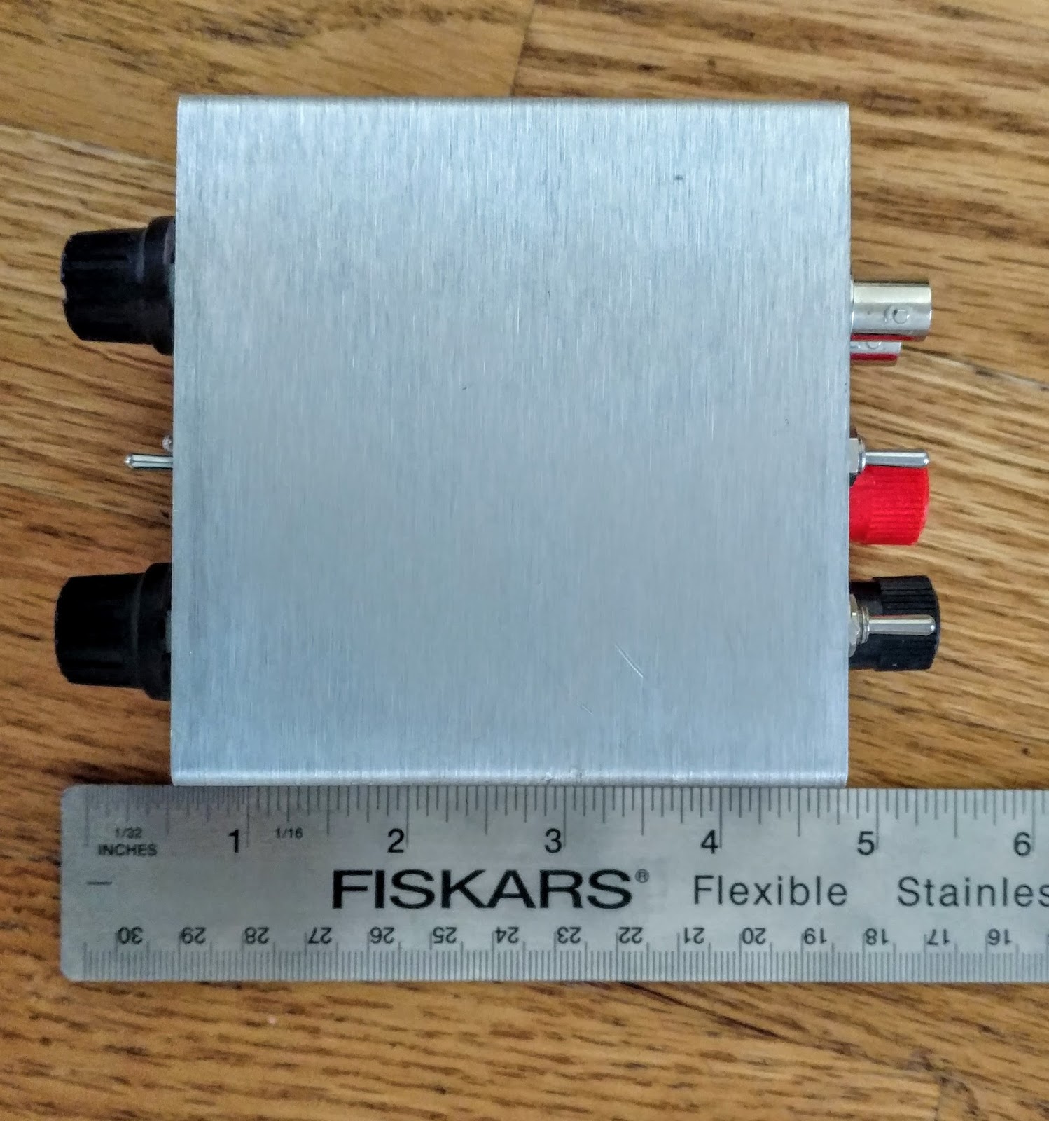
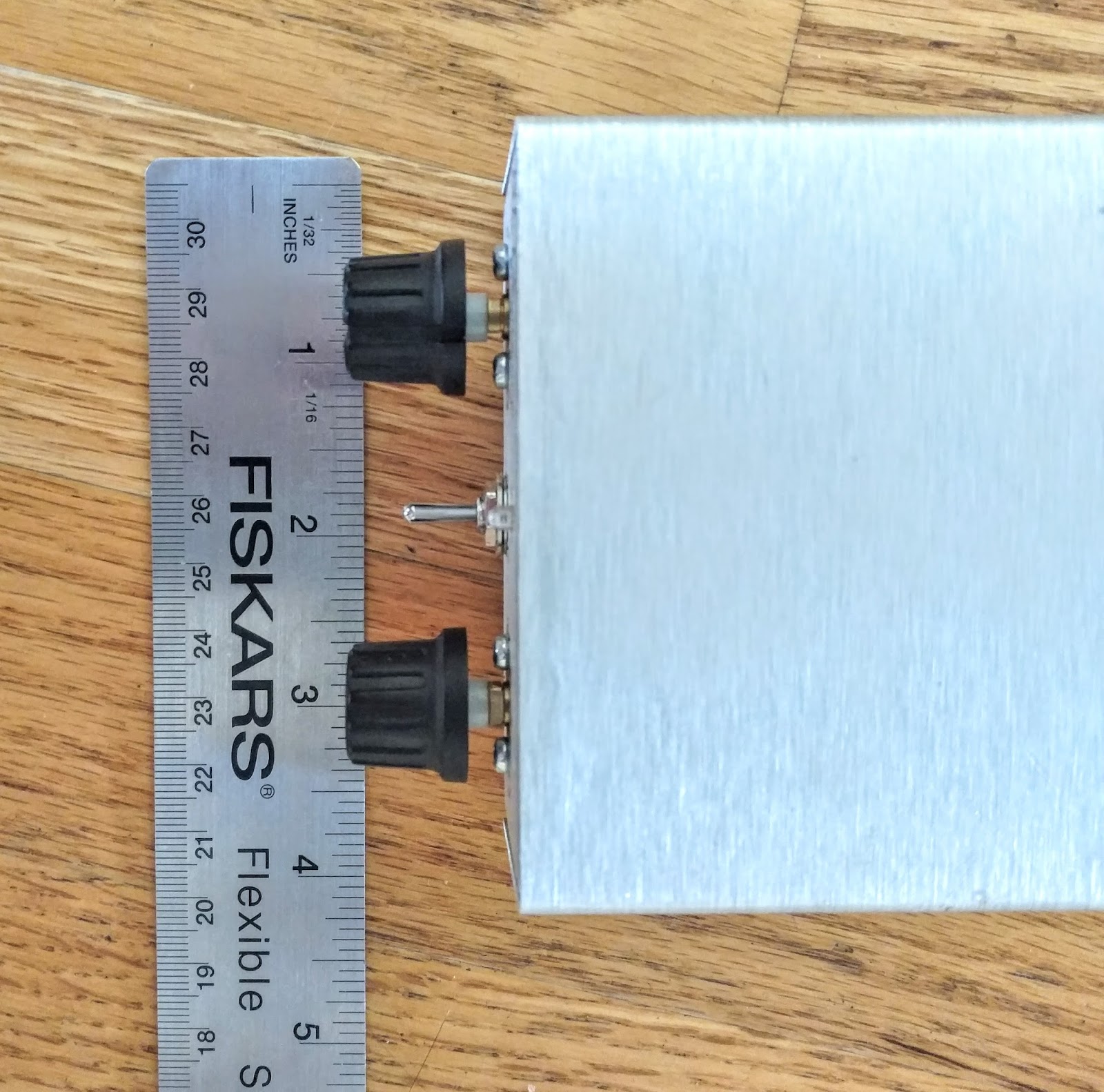
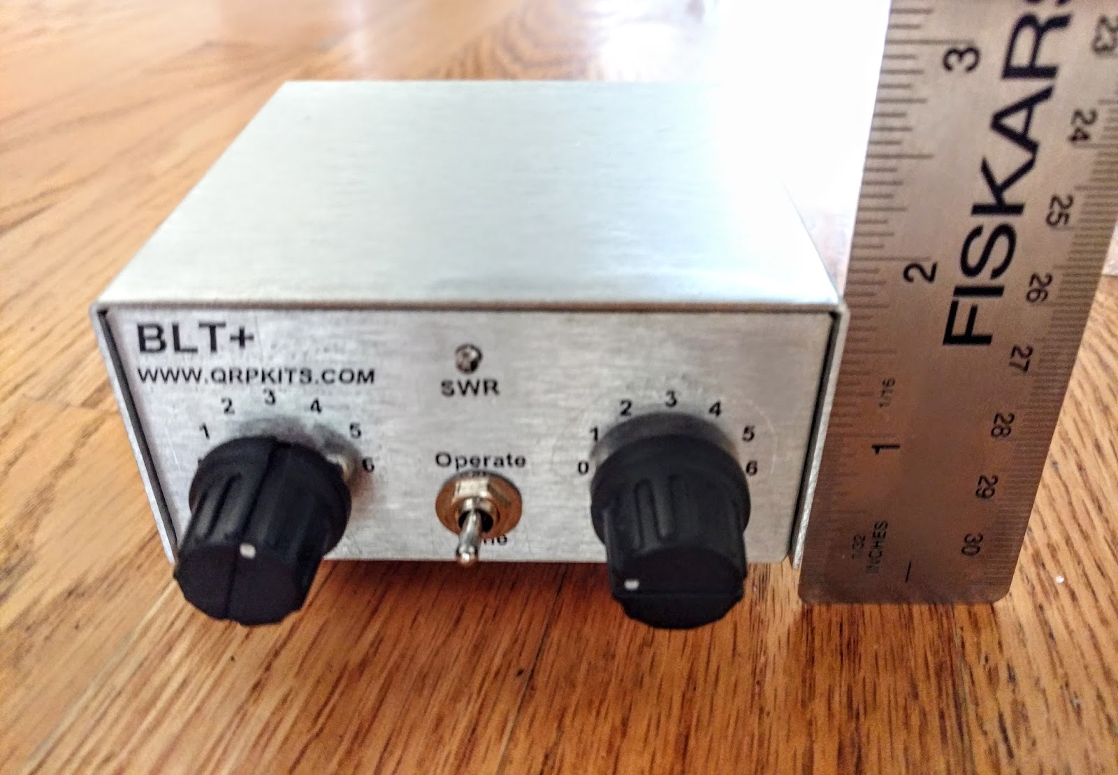
Remarks
Low cost oscilloscope kit (Bangood)
Steve G1KQH has tracked down yet another bargain. I think my SMA assembly skills are probably still not up to the task, but you can hardly go wrong at the price which includes free air-mail shipping. Another absolute bargain. I think Steve must have shares in Bangood!! If not, they ought to make him their UK agent, HI.
Here’s another one (kit), we could get our teeth into:
I have that many kits at the moment, I don’t know where to start next? If I come back in another life can we have a 48hour clock pse!73 Steve
http://www.g1kqh.talktalk.net/
First 40m Pixie QSO
At 1000z this morning I exchanged RST 579 reports with G6ALB who is 3km from me on my 40m Pixie on 7.023MHz CW. This was my first on-air QSO. Netting was perfect and I used the rig directly into my low Par triband antenna. An ATU might have helped. Andrew G6ALB said the channel was pretty busy but that I was a good RST579 with no hint of chirp. This afternoon we’ll put the rig on his spectrum analyser. I gave Andrew 579 probably reflecting the poorer MDS of the Pixie. I have no idea of his power or antenna.
My initial goals have been met: I built the kit and have managed a QSO on the air with it. With the fatigue associated with my brain bleed still very apparent (I am well and truly shattered currently), I was well pleased. A few more QSOs with the 40m Pixie would be good, HI.
$10 well spent. Excellent little kit. FB little transceiver. Works surprisingly well.
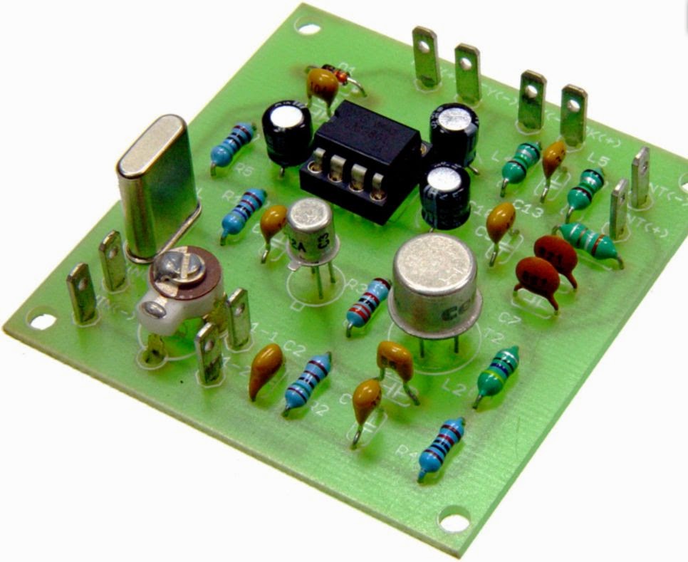
Genesis Q5 1W QRP kit from Australia
 |
| http://genesisradio.com.au/Q5/q5_1.jpg |
A trawl of the internet earlier found this kit, a 1W QRP transmitter for any band from 3.5MHz to 14MHz. It is available for S19.95 (US Dollars) + S9 (US Dollars) shipped anywhere worldwide. That seems pretty good value. Also on the website are SDR transceivers.
I last showed this particular kit on my blog 5 years ago.
See http://www.genesisradio.com.au/Q5/ for more details including how to order the various kits. Details on the page include parts lists, schematics and building details.
The are some pretty good SDR transceivers on this site.
So you want to play with a Pixie?
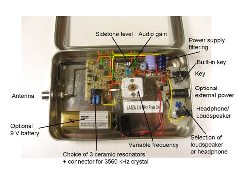 |
| My own surface mount version of the Pixie2 |
This page provides a guide to Pixie and related kits in a table format. These are simplistic single-band transceivers which are fun to build, yet they perform well enough to be used, although with some effort, for real contacts.
The idea of using the power amplifier transistor as a mixer seems to come from George Burt – GM3OXX – whose five transistor FOXX was described in 1983 in SPRAT. The basic design of the oscillator, PA/mixer and the simple keying has been more or less unchanged since RV3GM – Oleg Borodin – described the four transistor Micro-80 in 1992 in SPRAT. Later the Pixie 2 by WA6BOY replaced two of those transistors with the LM386 audio amplifier (QRPp 1995). Most later versions are variants of these designs.
Foxx | |
 Foxx-3 kit from Kanga, £29.95 | Incorporates a sidetone oscillator, changeover relay and low-pass filter. Different versions for the 80, 40, 30 or 20 m bands |
Micro-80 | |
 Kit from QRPme, $35.00 | Micro80D. Updated version with choice of high or low impedance headphone, polyvaricon tuning cap and board mounted connectors, 80 m. |
Pixie2 | |
 Kit from HSC Electronic Supply, $14.95 | For 80 and 40 m. Eham review |
 Kit from Kenneke, $29.95 | Includes 80 m crystal |
 Kit from QRPme, $40.00 | Lil Squall Transceiver ][. Several components and the output low pass filter are on sockets. Comes with a crystal for 40 m. |
 Ali Express Ham QRP DIY Kit Shack 40 m, $15.07 | 40 m version. Tuning pot for VXO. |
 Radi0kit, £22.00 | Enhanced Pixie2 which comes in 80, 40 and 20 m versions. Judging from the PCB layout it has an improved pin 7 muting circuit. |
What can we say to characterize these designs? One the one hand they are very simple to build and get to work. One the other hand they are also simple in the sense that they do not always perform very well. Therefore I don’t think I would recommend them to any novice ham. It takes some understanding of frequency offsets and sidebands in order to make real contacts. But many have had great fun with this minimalist transceiver which in its basic version puts out some 2-300 mW. And it encourages experimentation and modifications. Also, it should be remembered that it isn’t really necessary to get a kit, as the Pixie 2 is quite simple to build from scratch also. I did that myself.
The original designs and many variants and modifications are documented in the Pixie file document of SPRAT. There are many, many more clever modifications out there and I have my share on this blog also. To sort out and link to all the other pages is too daunting a task, so therefore I have focused on kits here. Finally I wouldn’t be surprised if the table is incomplete so I would appreciate comments if you think that something is missing.


