Posts Tagged ‘K3’
 OAFS failure
One of the things I had intended to do this year was install the external frequency reference module in my Elecraft K3 in order to get the best possible frequency accuracy for digital modes. To this end I had ordered an Off-Air Frequency Standard (OAFS) kit from Spectrum Communications so as to avoid wearing out my rubidium frequency standard. I had completed populating the OAFS board a couple of weeks before I ended up in hospital. So I thought I would try to see if it worked, as that would simply involve connecting up a speaker, ferrite rod antenna and power supply.
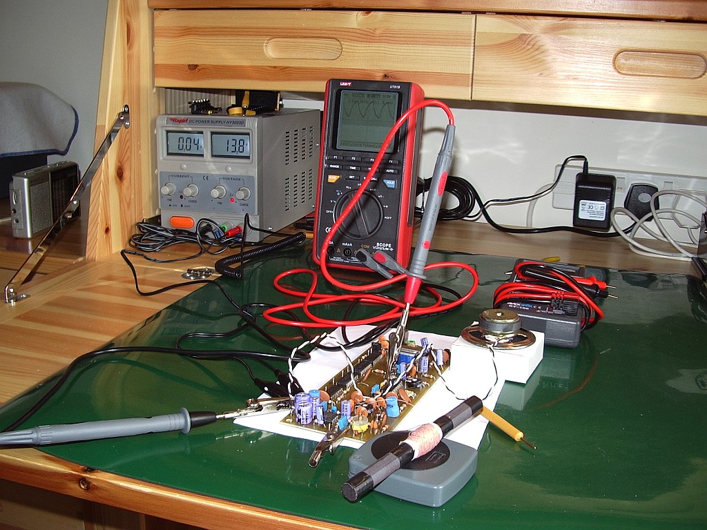
It began to look as if the predictions of the couple of people who commented or emailed when I first posted about the OAFS were going to be right. I could hear BBC Radio 4 long wave in the loudspeaker but it was very weak, presumably (as I had been advised) due to North Cumbria being a poor location to receive the transmission. When I checked the frequency of the phase locked loop it remained steadfastly on 216.4kHz regardless of the setting of the trimpot.
The instructions supplied with the kit suggested that it might be necessary to change a resistor value if the loop will not lock on to 198kHz so I wrote to Tony Nailer at Spectrum to see if he had a suggestion. Unfortunately his reply was that if the loop will not change frequency with the pot there must be a solder bridge or other assembly error. I checked my soldering as best I could and re-did any joints that looked suspect but the way my eyes are now any sort of cross checking between the schematic and the circuit board to look for errors is impossible.
I haven’t really figured out what is wrong with my eyes but it is as if they no longer have the ability to vary focus. I can only see clearly what is at the exact focal point of whatever spectacles I am wearing. When something is out of focus my head swims and I have to close my eyes for a few minutes to steady it again. So any sort of constructional work now is well-nigh impossible.
Tony offered to get the OAFS working for me for a fee if I sent it to him, but at this point I think it would be a waste of money. I can’t see myself installing the frequency reference boards in my K3 now even if I still had the same interest in doing so. So I think the OAFS is destined for the G4ILO junkbox.
Ultraportable Elecraft KX3
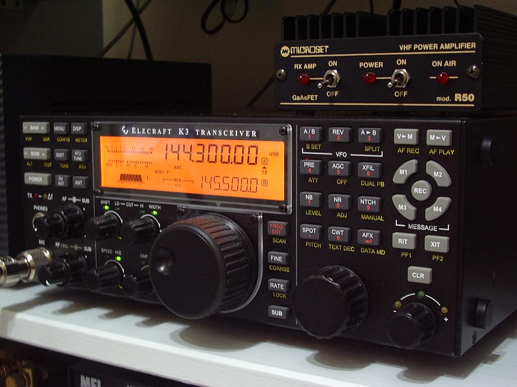
UPDATE: Steve G4GXL’s 10 minute YouTube video of Wayne N6KR’s quick overview of the new KX3 is available from http://qrparci.org. Also there are early photos on Twitpic here - courtesy of Jeff Davis KE9V including this one:

One of the earliest - and clearest - photos of the new KX3 taken at the Elecraft stand in Dayton by Jeff Davis KE9V
Under the tantalising subject line “Something *really* new at Dayton from Elecraft” and while en route to Dayton – Elecraft’s Wayne Burdick N6KR announced to the Elecraft email lists a very interesting new offering to be launched there – the KX3 and a companion 100W amp, the KXPA100.
According to Wayne, the KX3 handles all modes, SSB/CW/AM/FM/DATA (the latter including built-in PSK31 and RTTY encode/decode/display).
He promised to post full details and photos later this weekend. But that was too intriguing for the list. This is an edited and probably repetitive summary of what they managed to find out about the new set.
KX3: Ultra-compact K3/KX1 hybrid, 160-6 m, 10/100 W, all-mode, 32-bit DSP/SDR, 1.5 lbs.
Ultraportable:
- 1.5 lbs (680g)
- 1.7″ x 3.5″ x 7.4″ (4.3cm x 8.9cm x 18.8cm)
- extended KX1 form-factor (KX1 - 1.2 x 3 x 5.3″ (3 x 7.5 x 13 cm) KX1 base weight 9oz / 255g)
- internal battery pack & charger
- internal wide-range ATU
- new adjustable, attached keyer paddle
…and a K3-like front panel, including the same LCD.
RX-mode current drain ~150 mA. Very efficient on TX, with dual-output-impedance 5W/10W PA.
The optional 100W amp is in an external chassis. The internal amplifier is 10W with switchable impedance matching so it can also operate with maximum efficiency at 5W.
PA output impedance switch allows efficient 5-W use from internal batteries, or 10 W from external supply.
KXPA100 - 100 W+ with new high-performance external amp/ATU that works with most 5W to 10W rigs.
>Same flat layout as the KX-1 – just bigger box I would assume????
Yes, but with new fold-up rear tilt-feet.
>…and a K3-like front panel, including the same LCD.
>
> And it makes use of EVERY display on that LCD?? Carumba!Not quite. I think there are a couple annunciators that are not used. But it’s amazing that the design team managed to fit almost all the features of a 10W K3 into a box that is a small fraction of the size and weight. And with space left over for an internal battery pack!
By the time we’re done, we’ll be using every icon.
Totally different architecture than the K3, of course. (Wayne N6KR)
RX-mode current drain ~150 mA. Very efficient on TX, with dual-output-impedance 5W/10W PA.
> More $$$ or less $$$ that the regular K3?
Much less.
> Dual output impedance 5w/10w pa? I don’t understand.
The MOSFET 10-W amp stage includes an output transformer with both 1:4 and 1:1 windings. When using low power, or when running from internal batteries, the 1:1 winding is used, which optimizes efficiency at about 5 W, greatly reducing transmit current drain. The 1:4 winding is used when running higher power (using an external supply).
> One email said 10w/100w models. Is that correct?
The 1.5-pound radio itself puts out 10 watts+. We’ll also be describing a new, high-performance 100-watt+ companion amplifier/ATU for fixed-station/mobile use. It will work very well with other 5 to 10-W radios besides the KX3.
From follow-up discussion etc it appears as if the base price of the KX3 will be US$799. Availability towards end of 2011. See video for a pretty comprehensive outline of features. Options for the KX3 include roofing filters, internal battery pack and ATU similar to one of K3. Truly an exciting trail friendly radio!
I’ve created a page where I’ll pull together all the available information there is about this ultimate trail friendly radio.
Round the back way

Back in the early QRP days of Elecraft, there were some K2 owners who were such CW diehards they were uncomfortable with having a radio that possessed a microphone socket. One or two of them described to the Elecraft email reflector how they had blanked off the offending socket. Despite the evidence in the picture on the right, I have not joined this fraternity. I have simply started using the rear microphone and PTT connector on my K3. I have thought for some time that the front panel connector is an accident waiting to happen, and I finally decided to make the move before it did. (And before anyone comments about the dust in the photo let me just say that one of the few benefits of deteriorating eyesight as you get older is that you don’t notice it!)
Front panel microphone sockets are pretty much the norm in ham radios. However in most radios they are secured directly to the metal front panel or, in the case of radios with a plastic fascia to the metal chassis behind it, using a locking nut which tightens the chassis against the ring cast into the socket so that it is rock solid. You could tug at the microphone cable all you want or bash the connector with a hammer and you would be unlikely to cause any damage to the radio itself.
In the K3, the microphone connector comes soldered to the front panel board. There is no possibility of securing it to the metal front panel. The ring that would normally sit on the outside of the mounting hole actually slips through the hole in the front panel so all the rigidity is provided by the PCB. The front panel hole limits movement up and down or side to side to a certain extent. But it does not provide any protection from movements fore and aft. I wonder about the effects of constant small side to side movements on the soldered joints connecting the pins to the board. And I feel sure that if I accidentally leant on the microphone plug, supporting my weight as I tried to make some connection round the back, I could damage the front panel PCB by snapping the microphone socket right off.
As the outer body of the microphone connector is not physically attached to the radio itself it is not electrically grounded. Whilst installing the K144XV transverter board I noticed that grounding is provided by a piece of bare wire that loops round the threaded part of the connector and is soldered to the front panel board. This may have been a modification that I did myself when I assembed my K3 three years ago. What this wire loop does not do is prevent the outer metal part of the microphone connector from turning relative to the insulated centre bearing the 8 pins that are soldered to the PCB.
Because of the perceived risk of damaging the front panel board by accidentally putting my weight on the microphone plug I have been in the habit of disconnecting the microphone whenever I need to lean over the K3 to grope round the back. So the microphone connector has been on and off rather a lot. Recently I observed a tendency for nothing to happen when I pressed the PTT on my desk mic after reconnection. It then became apparent that the outer metal part of the plug has become slightly loose and can be twisted several degrees relative to the centre. I’m pretty sure this is due to the plug body not being secured to the chassis of the radio so there is nothing to take the strain of tightening and untightening the microphone plug. Hence my decision to give up using the front panel socket and move round to the back before the problem got any worse.
My shack is very cramped so I had shortened the cable on my Heil desk mic to eliminate unnecessary length when plugged in to the front of the K3. Consequently it would not reach round to the back. Rather than rewire the microphone I decided to make an extension cable using a line 8-pin socket, retaining the option of using the front connector if I want. I purchased the line connector quite inexpensively from an eBay seller (where else?)
These connectors are much easier to work with than the mini-DIN connectors I have recently been using rather a lot. The pin numbers are clearly visible, but it’s a good job I checked: in the connector I had the pins had been installed in the metal socket offset by one pin position so pin 1 was labelled pin 7 etc! This could easily have been confusing and so my brain cells got a bit more exercise than expected making sure I got the connections right.
I changed the microphone configuration in the menu to use the rear mic socket and so my microphone is now plugged in round the back. It would be interesting to know whether any other K3 users have had problems with this front panel socket. Once, I would have posted about it on the Elecraft email reflector, but that would only result in several replies from kool-aid drinkers saying that it hasn’t happened to them so it must be my fault.
K144XV comments
The K144XV eventually turned up late on Thursday afternoon. After the board modifications had been performed, installing the transverter module was easy following Elecraft’s exemplary instructions. I had to remove the KIO3 module in order to remove the KXV3 transverter module and replace it with the KXV3A, which has a couple of additional connectors for the internal transverter, then replace the KIO3. I also had to replace the side panel of the K3 with one that has some extra holes for securing the transverter. The stiffener that runs across the top of the case is also replaced by one with a cutout where it passes over the K144XV.
Due to the lateness of the hour I was a bit tired and also focussed on getting the job finished so the shack could be restored to normality so I never even thought about taking some pictures. The module comes as a complete screened box not a bare board as shown in some of the pictures on the Elecraft website. It is quite a little beauty and the way it all fits into the K3 is a work of art.
Although described as a 10W module the instruction manual states that you should get at least 9W with 1.0mW input to the transverter. I actually got about 11W so the power output comfortably exceeded spec. At my noisy location I can’t make any meaningful observation about sensitivity – any half decent 2m radio will be sensitive enough. But I did notice that S meter readings are extremely low. I see no movement at all on a clear frequency despite the noisy location and a repeater that lights all the signal strength bars of my TM-D710 registered just S4 on the K3. I never take any notice of S meters anyway so I’m not unduly bothered. The amplifier “brick” I will use with this has its own built-in preamp which will boost S meter readings if I want.
The 2m amplifier I have was designed to be driven by an FT-817 so it only requires an input of 5W. I found that I needed to reduce the drive to the transverter to a mere 0.15mW to achieve this level of output. I don’t know how accurate the low level output power settings of the K3 are but the relationship between 28MHz drive in and power out is definitely not linear. However the signal on SSB sounded pretty clean when monitored on the FT-817.
The calibration of the transverter local oscillator is done using software, not by trying to tweak a trimmer capacitor by a fraction of a hair’s breadth, which is a blessing. There are two local oscillators in the transverter to provide coverage of the full US 2m band (144 – 148MHz) using the same 28MHz – 30MHz range (interestingly the top 2MHz is not disabled in European rigs.) The transverter module is calibrated at the factory and you have to enter the calibration values into the K3 using the configuration menu. I checked the result using my FC-1 frequency counter and also my FT-817 and it appeared to be accurate to within 100Hz which is about as good as I can get. Later I listened on the GB3VHF beacon frequency and waited for the beacon to come out of the noise. I believe this beacon’s frequency is GPS locked. The frequency appeared to be out by 120Hz so I was able to adjust the calibration value and get it spot on.
The signal to noise ratio on a weak FM signal is definitely better on the K3 than with my other 2m rigs but I don’t see the K144XV as being the solution for people whose primary interest 2m FM. One reason is that a 2m mobile rig is cheaper and allows you to monitor and work 2m FM at the same time as using your K3 for something else. Another is that the K3 doesn’t really handle channelized operation very well. The memory system has improved considerably since the early days but using the VFO to scan through memories rather than a click stop rotary control doesn’t work for me, especially due to the laggy response of the K3 to the turning of the knob.
But I think the K144XV is an excellent option if you want to work 2m DX. The receiver sounds quiet and clean and having all the QRM fighting and weak signal detecting tools of the K3 available on 144MHz is a real bonus. Now I just have to wait for some 2m SSB activity to try it out!
K3 mod fun
Today I have been waiting for Parcel Farce to deliver a K144XV internal 2m transverter board for my K3. I hate doing modifications to the K3. First there is the hassle of disconnecting all the cables that are plugged in the back. I have to disconnect practically everything in the shack in order to remove the shelf above the K3 so I can see what I am doing.
I also dislike making modifications to the K3 itself. It makes me nervous thinking of the cost and expense if I mess something up and it doesn’t work. I’m starting to think that if I want to stick with the K3 it would be better to sell this 3 year old one and get a new current model. Because there have been so many modifications now since my serial number 222 was produced. I haven’t done many of the mods because I don’t think they make a worthwhile difference or because they involve obtaining an exchange board from Elecraft and the cost of doing this including shipping, VAT and tax collection fee is more than it is worth. But the internal 2m module seemed in the end to be the best solution for providing a capability for 144MHz SSB, even though it involved exchanging my KXV3 transverter interface board for a KXV3A.
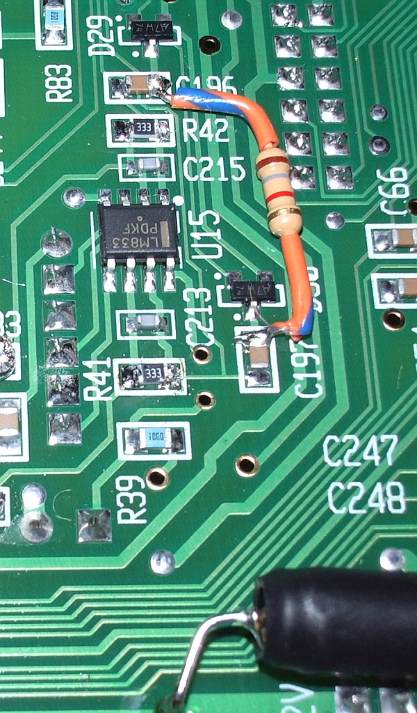
In order to install the K144XV it is necessary on older K3s like mine to mount a socket on the main board to provide power. This involves removing the bottom panel of the rig. I thought that while I was doing that I would do another mod to increase the IF output which would be necessary should I ever want to use a P3 panadapter with the rig. The mod involves changing one resistor, oddly specified at 13K. An enquiry on the Elecraft reflector about whether the value was that critical resulted in the kind offer from Ian GM3SEK to send me a couple of SMT resistors so I could do the mod. Without Ian’s help I would have had to leave the mod until I got a P3 and Elecraft sent the replacement part because SMT resistors aren’t something you can buy from Maplin in quantities of one or two off.
I had shied away from doing mods involving SMT parts before but I found that it wasn’t too hard. However I did need to use a high magnification lens in my head-mounted visor. I was initially alarmed to see that the resistor I had to change wasn’t one of the fairly big SMT resistors that are normally used in kits using these type of parts, it was a really tiny one. I used two soldering irons, one at each side, and then flicked the resistor off. After cleaning the pads with a bit of solder wick I then took one of the replacements using a trimming tool with a bit of Blu-Tack on the end and held it in place while I took a blob of solder on the end of my smallest bit and tacked one side of the resistor into place. Then I did the same to the other side. Job done.
Although the high magnification makes it possible to see the tiny parts, it can’t do anything about shaky hands. My hands seemed fairly steady this morning but it is a different picture through a high magnification lens and you don’t need to move far to shift the component out of its precise spot, which of course I did. I decided this is no job to be fussy about. The resistor was slightly skew-whiff, but it was attached to the board and my ohm meter said everything was OK. Perhaps I could get a job working for MFJ. 🙂
The package from Elecraft still hadn’t arrived so I decided to pull up the instructions for installing the K144XV from Elecraft’s website to see what was involved. As I mentioned, I needed to install a terminal to provide 12V to the transverter module. This is a bit of a kludge as the K144XV wasn’t even a planned option at the time my K3 was made so there isn’t a proper place for this terminal. You have to solder it in using a “via” that wasn’t actually designed for this use. Unfortunately that via had been used by one of the leads of a wire-ended capacitor used in another mod to improve the low frequency audio response.
The instructions mention this possibility and suggest an alternative via. However that via was obscured by the components used to perform yet another mod, this time the hardware AGC modification. Lacking the confidence to remove and replace SMT parts I had used wire ended components to do this mod. There was no alternative but to remove the mod and do the SMT version. Elecraft had provided both types of components and fortunately I hadn’t lost the SMT ones. However they had not provided any spares and I was conscious that one false move sending a resistor pinging off to oblivion would result in a K3 I would be unable to use until I could find a replacement. That didn’t help the shaking hands one bit!
Fortunately it all went well, with the results shown in the picture. (The resistors I had to replace are the ones marked 333.) So that’s done. But still no transverter. Where the hell are you, Parcel Farce?
Changes to 2m gear
I have had a bit of a change round in the shack recently. Since getting the Kenwood TM-D710 which is used for 2m FM which is the vast majority of my VHF activity, the Icom IC-910H has really been under-utilized. 70cm is a dead band here and there isn’t too much 2m SSB activity. Besides, I never really liked the Icom. So I decided to swap it for an old Spectrum Communications transverter that I have and sell it in the new year.
The Kenwood has been moved into the “second rig” operating position. And the desk mic I used with the Icom is now attached to the Kenwood. I had some CAT5 UTP network cables which are terminated in the same type of plug Kenwood uses for a mic connector, so I cut one in half and made up a cable for the desk mic. Despite being unshielded (UTP stands for Unshielded Twisted Pair) there doesn’t seem to be any RFI even at 50W. And the reports I have had so far suggest that it sounds good.
The Spectrum transverter runs about 20W output. This is less than I would like for SSB. My plan was to set the transverter drive so the peak output was 5W and use it to drive a 50W linear amp that I have. But when I set the power to 5W, as soon as I put the cover on the case it dropped to 1.5W. So I thought that perhaps the whole thing needs realignment.
Unfortunately it did not go well. The transverter, which I bought umpteenth-hand in a private sale some time ago, had obviously suffered the depredations of the ham-fisted twiddler. Two of the ferrite tuning cores in the Toko coils were cracked and could neither be adjusted nor removed so they could be replaced. Despite this, the transverter receives pretty well.
However, while trying to realign the transmit side to solve the problem of changing power output when the case cover goes on, I noticed that there was often power out when the key was up. There was clearly some instability present. Although I could adjust the trimmers so there was no unwanted output, I could not eliminate the changing output as the case cover is put on. I do not have the test equipment (a spectrum analyzer) to be sure that the output is clean and I started to have doubts about the whole thing.
I did not want to risk wiping out the neighbour’s TV reception whenever I use 2m SSB. So I decided to scrap the transverter and order an XV144 internal transverter module for my K3. It is on its way, and hopefully will arrive in the UK before the increase in VAT takes effect.
Taking part
On Saturday I blew the dust (literally!) off my K3’s microphone. After I had finished sneezing, I started making some contacts in the CQ WorldWide SSB DX Contest.
This was not intended to be a serious competitive effort. My intention was to spend all of the time I could spare that weekend making contest contacts and see how many stations I could work. I spent about an hour on Saturday morning before going with Olga to the garden centre, and a couple of hours in the afternoon. On Sunday I was up earlier than normal because the clocks went back overnight, so I operated for about three hours in the morning before lunch. I had intended to do some operating in the afternoon as well but the three hours in the morning had left me feeling a bit tired and stiff so I went for a walk after lunch and then fell asleep on my return home. Getting old is my excuse!
I made a total of 154 contacts in 43 different countries and 4 continents during my six hours or so of operating. The detailed breakdown, for those interested, is shown in the screen grab of the contest statistics dialog from KComm (the Extra field shows the number of CQ zones.) This would give me a claimed score of 17,487 points if my calculations are correct, which by comparison with last year’s results would place me well down the second half of the All Band Single Operator Low Power Unassisted results table.
This was the first time I had made such an effort for an SSB contest. Until now I hated turning on the radio during big SSB contests because the bands sounded like bedlam. But I had never tried with the K3 before. Instead of a mush of intermod, splatter and AGC pumping I could hear everything clearly. Sometimes I could hear two or three stations on the same frequency simultaneously, one in the foreground and a couple in the background. And the superb DSP filtering made it easy to shut out close-by stations so I could copy a weaker one. I often had the passband down to 1.8kHz and copy was still crystal clear.
Initially I started off just working the loud ones because I didn’t want to waste the serious contesters’ time by making them struggle to hear my call. But I found there was no hard and fast rule relating how strong a station was with whether they heard me. One Finnish station, 10dB over 9 with me, just kept on calling as if I wasn’t there. But many weaker ones came right back to my first call.
Frustratingly, a significant number of stations came back to me as “Golf 4 Lima India Oscar” – exactly the same error that was made when I ordered my QRSS beacon kit a couple of weeks ago. What is it about my call? This doesn’t happen on CW (though I used to get replied to as G3ILO very often as the holder of that call is a well known QRP CW operator.)
Conditions didn’t appear to be very good this weekend. I’d hoped to hear some interesting DX on 10m but I heard hardly anyone at all on the band. As always, 20m was the liveliest band, but I made almost as many contacts on 15m, probably because the QRM was less making it easier to make contacts.
I didn’t work any DX and I only worked one all time new DXCC entity – Svalbard, JW5E. I did hear a VK on 15m on Sunday morning but he had a big pileup going and after trying for about five minutes I decided not to waste any more time and move on.
Despite my unspectacular results I thoroughly enjoyed my few hours in the CQ WW DX SSB contest. No doubt QRZ.com and other online forums will be full of grumbles about contests taking over the band for the entire weekend, the only time working people can get on the air etc etc. But if you can’t beat them, why not join them?
My feeling is that contesting is one of the many different activities you can pursue and to get the most from the hobby you should try as many of those different activities as you can. As this post has hopefully shown, having indoor antennas is no obstacle to working a decent number of stations and earning a respectable score for the time spent. It’s not the winning, it’s the taking part that counts. I certainly felt like a real participant in this radiosport event and I look forward to seeing my call in the results table next year.


