 K3 mod fun
Today I have been waiting for Parcel Farce to deliver a K144XV internal 2m transverter board for my K3. I hate doing modifications to the K3. First there is the hassle of disconnecting all the cables that are plugged in the back. I have to disconnect practically everything in the shack in order to remove the shelf above the K3 so I can see what I am doing.
I also dislike making modifications to the K3 itself. It makes me nervous thinking of the cost and expense if I mess something up and it doesn’t work. I’m starting to think that if I want to stick with the K3 it would be better to sell this 3 year old one and get a new current model. Because there have been so many modifications now since my serial number 222 was produced. I haven’t done many of the mods because I don’t think they make a worthwhile difference or because they involve obtaining an exchange board from Elecraft and the cost of doing this including shipping, VAT and tax collection fee is more than it is worth. But the internal 2m module seemed in the end to be the best solution for providing a capability for 144MHz SSB, even though it involved exchanging my KXV3 transverter interface board for a KXV3A.
In order to install the K144XV it is necessary on older K3s like mine to mount a socket on the main board to provide power. This involves removing the bottom panel of the rig. I thought that while I was doing that I would do another mod to increase the IF output which would be necessary should I ever want to use a P3 panadapter with the rig. The mod involves changing one resistor, oddly specified at 13K. An enquiry on the Elecraft reflector about whether the value was that critical resulted in the kind offer from Ian GM3SEK to send me a couple of SMT resistors so I could do the mod. Without Ian’s help I would have had to leave the mod until I got a P3 and Elecraft sent the replacement part because SMT resistors aren’t something you can buy from Maplin in quantities of one or two off.
I had shied away from doing mods involving SMT parts before but I found that it wasn’t too hard. However I did need to use a high magnification lens in my head-mounted visor. I was initially alarmed to see that the resistor I had to change wasn’t one of the fairly big SMT resistors that are normally used in kits using these type of parts, it was a really tiny one. I used two soldering irons, one at each side, and then flicked the resistor off. After cleaning the pads with a bit of solder wick I then took one of the replacements using a trimming tool with a bit of Blu-Tack on the end and held it in place while I took a blob of solder on the end of my smallest bit and tacked one side of the resistor into place. Then I did the same to the other side. Job done.
Although the high magnification makes it possible to see the tiny parts, it can’t do anything about shaky hands. My hands seemed fairly steady this morning but it is a different picture through a high magnification lens and you don’t need to move far to shift the component out of its precise spot, which of course I did. I decided this is no job to be fussy about. The resistor was slightly skew-whiff, but it was attached to the board and my ohm meter said everything was OK. Perhaps I could get a job working for MFJ. 🙂
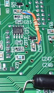
The package from Elecraft still hadn’t arrived so I decided to pull up the instructions for installing the K144XV from Elecraft’s website to see what was involved. As I mentioned, I needed to install a terminal to provide 12V to the transverter module. This is a bit of a kludge as the K144XV wasn’t even a planned option at the time my K3 was made so there isn’t a proper place for this terminal. You have to solder it in using a “via” that wasn’t actually designed for this use. Unfortunately that via had been used by one of the leads of a wire-ended capacitor used in another mod to improve the low frequency audio response.
The instructions mention this possibility and suggest an alternative via. However that via was obscured by the components used to perform yet another mod, this time the hardware AGC modification. Lacking the confidence to remove and replace SMT parts I had used wire ended components to do this mod. There was no alternative but to remove the mod and do the SMT version. Elecraft had provided both types of components and fortunately I hadn’t lost the SMT ones. However they had not provided any spares and I was conscious that one false move sending a resistor pinging off to oblivion would result in a K3 I would be unable to use until I could find a replacement. That didn’t help the shaking hands one bit!
Fortunately it all went well, with the results shown in the picture. (The resistors I had to replace are the ones marked 333.) So that’s done. But still no transverter. Where the hell are you, Parcel Farce?


