Posts Tagged ‘GPS’
 Better with SMA
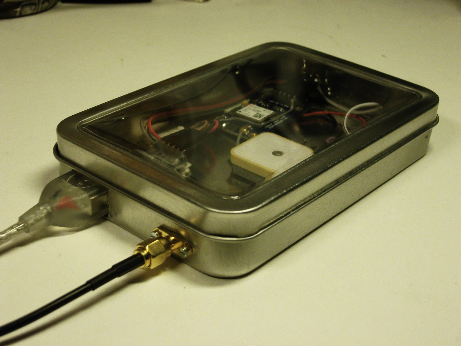
I had some trouble closing the lid on the “Just good enough 10 MHz GPS reference” due to the size of the BNC jack. Therefore I changed it to an SMA (SubMiniature version A) female jack. A thin cable connects it to the K3’s SMA input and there is no need for any SMA-BNC adapter on that end.
At the same time I moved the GPS antenna to a more central location in the tin, in the hope that the walls of the tin would interfere less with GPS reception. That’s the theory anyway, if it matters much in practice is a different story.
 Actually, I think I’m going to use SMA more often with these clear top tins and also Altoids tins. They take up much less space and are easier to install and to work with.
There aren’t any high power applications for circuitry in such tins, so I cannot so any reason why the SMA won’t work just as well or even better than the BNC.
Other related posts about the 10 MHz reference:
- Just good enough 10 MHz reference (3 Oct 2015)
- Curing amnesia in the 10 MHz GPS reference (19 Nov 2015)
- Improved GPS reception with a ground plane (11 April 2016)
Better with SMA
I had some trouble closing the lid on the “Just good enough 10 MHz reference” due to the size of the BNC jack. Therefore I changed it to an SMA (SubMiniature version A) female jack. A thin cable connects it to the K3’s SMA input and there is no need for any SMA-BNC adapter on that end.
At the same time I moved the GPS antenna to a more central location in the tin, in the hope that the walls of the tin would interfere less with GPS reception. That’s the theory anyway, if it matters much in practice is a different story.
Actually, I think I’m going to use SMA more often with these clear top tins and also Altoids tins. They take up much less space and are easier to install and to work with.
There aren’t any high power applications for circuitry in such tins, so I cannot so any reason why the SMA won’t work just as well or even better than the BNC.
Just good enough 10 MHz GPS reference
Some time ago I noticed that the Ublox Neo-7M GPS has a 10 MHz output which is locked to the GPS system’s accuracy. Most people kept saying how useless it was due to excessive jitter unless it was cleaned up with a phase locked loop of some sort.
At about the same time I installed the external reference input for my Elecraft K3. The K3EXREF enables the K3’s frequency to be locked to an external 10 MHz reference. What struck me was how its function is described:
- The frequency of the internal oscillator of about 49.38 MHz is continuously measured and averaged, obtaining a value to the nearest 1 Hz.
- The K3EXREF does not phase lock the K3’s reference oscillator and the external 10 MHz source has no impact on the K3’s phase noise performance.
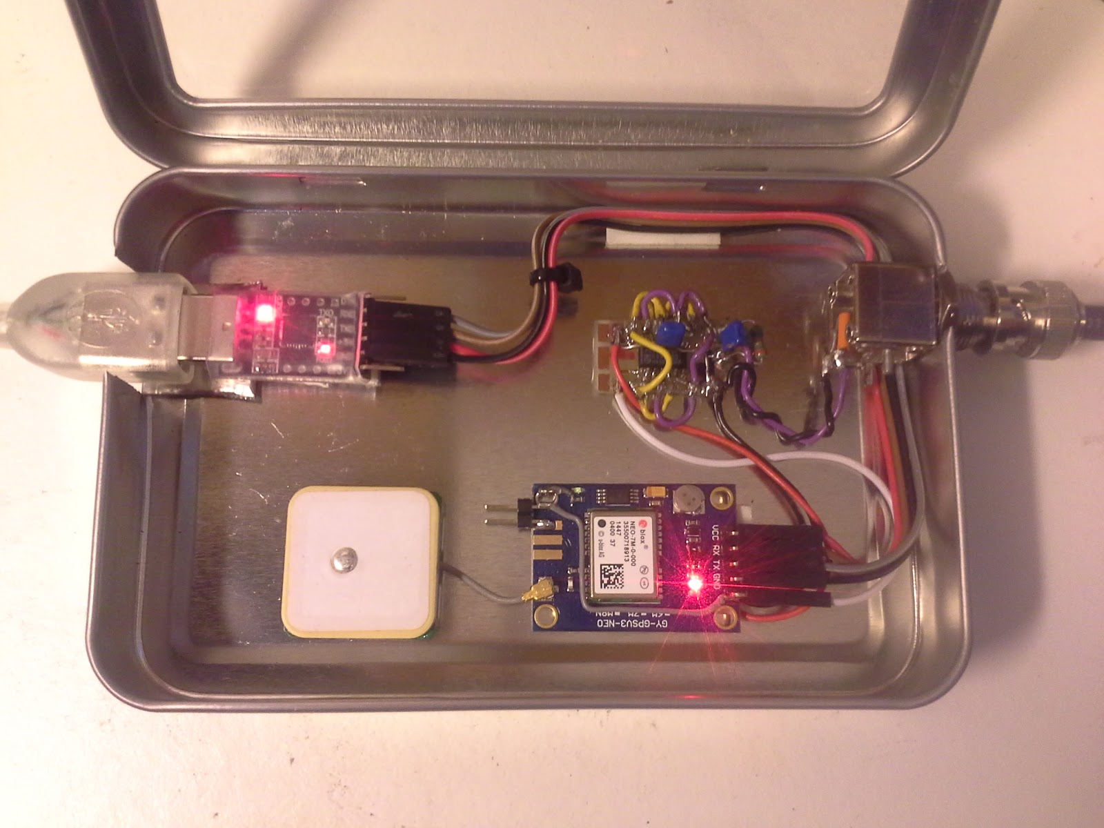
This got me wondering if the Neo-7M would be just good enough as a reference and that all the averaging internally to the K3 would take care of the jitter. I ordered one from Ebay for USD 12-13 together with an USB interface (USD 1.5) and hooked it up. (Actually the NEO-7M already has a built-in USB interface, but my board doesn’t support it). The result is shown above as assembled in a clear top tin. In my wooden house I can receive GPS indoors, so I have no need for an external antenna
 The K3 accepts the input and I see the star in REF*CAL blinking. Just after turn-on of the K3 my 49.38 MHz reference frequency ends in …682 and after 10-15 minutes it has fallen and stabilized to …648, i.e. 34 Hz down in frequency. This is just 8 Hz off the reference value I determined manually was the right one when my K3 was new in 2009 (49.379.640).
All this taken together indicates to me that the K3 finds this 10 MHz acceptable for locking. The measurement to the nearest Hz, implies a measurement time of the order of 1 second and that seems to be enough to smooth out the jitter from the Neo-7M.
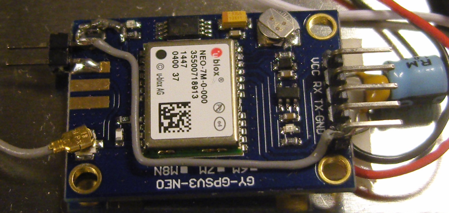
In order to get this to work I had to do some modifications to the GPS unit. First I had to get access to the timepulse on the chip’s pin 3. My connection is inspired by that of G4ZFQ and consists of a small wire from the left-hand side of the 1k resistor to the upper left hole. From there another grey wire goes below the chip and to the 5-pin header which is soldered to the Vcc, Rx, Tx, Gnd pins. The 5th pin is cut off and is just attached to the other pins through the plastic hardware.
The second modification was required in order to get it to run from the somewhat noisy USB 5 Volt supply. That took some decoupling between the Vcc and Gnd pins (220 uF and 0.1 uF in parallel), visible to the right in the image above, using good engineering practice to keep the wires as short as possible.
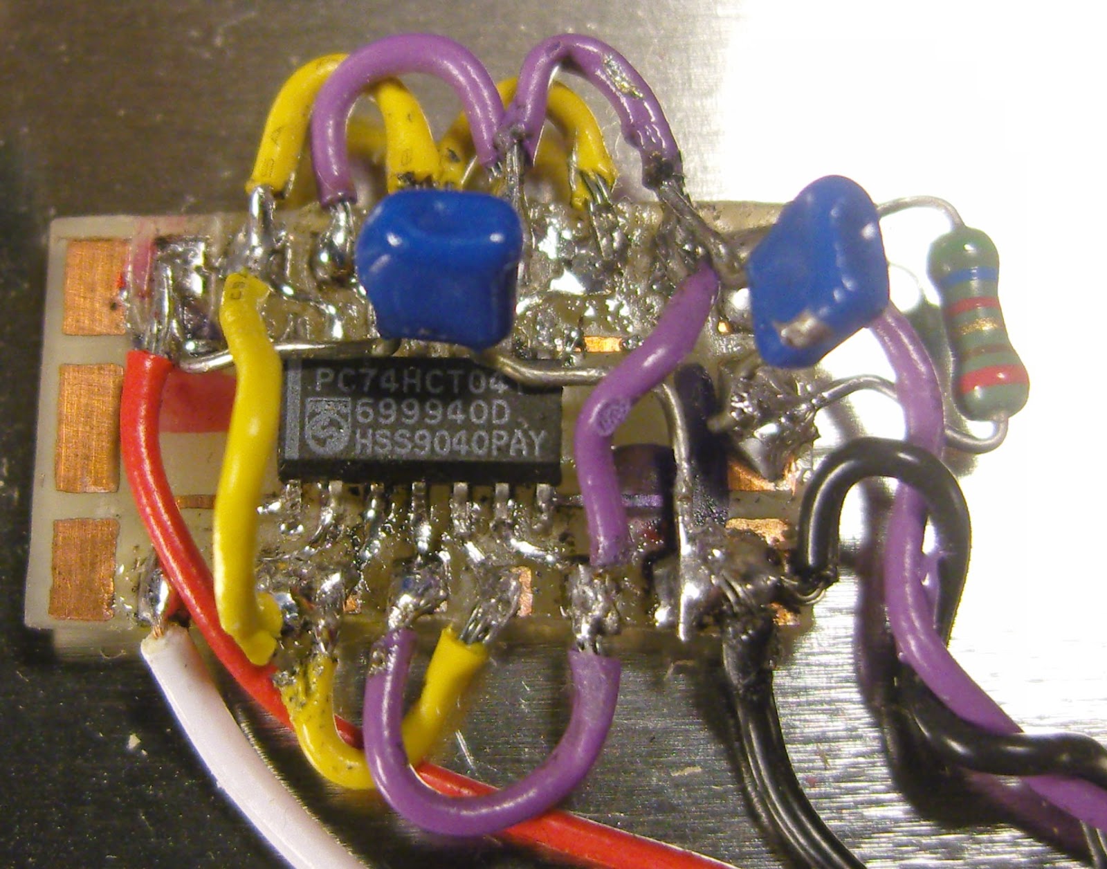 The timepulse is a 3.3 Vp-p output which cannot drive anything below 400-500 ohms impedance. Therefore I added a 74HCT04 driver that I have assembled on a little homemade SMD to DIL adapter PCB (easy to find on Ebay). It serves as a driver to feed the 10 MHz to the 50 ohm input of the K3EXREF.
The HCT04 IC has 6 inverters. One of them takes the input signal from the Timepulse output of the GPS IC and buffers it to drive the 5 other inverters in parallel. This is shown in the schematics at the end of this blog post.
The 5Vp-p output from the buffers is fed via 56 ohms to a connector that goes to the K3EXREF input. This is in accordance with the K3EXREF manual which says: “The 10 MHz source should have a signal level between +4 dBm and +16 dBm, nominal. For square wave sources, 2VDC to 3.3VDC peak is optimum. If the source is a 5V logic level, use a 50-ohm resistor in series with the input.“
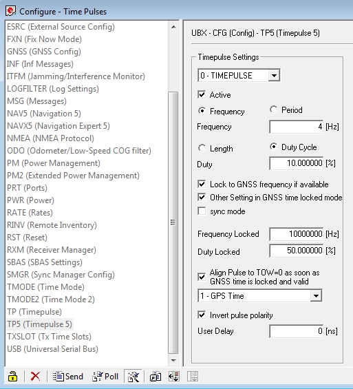 In order to set up the GPS I have used the u-center program (Menu: View, Configuration View, TP5 (Timepulse 5)) from Ublox and set it up with the parameters shown to the right. It blinks at 4 Hz before the signal is acquired and then switches to 10 MHz. This can be observed on the green LED connected to the Timepulse output also as it switches from blinking to a half-lit status.
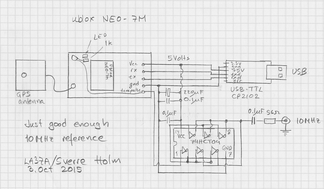
See also
Just good enough 10 MHz reference
Some time ago I noticed that the Ublox Neo-7M GPS has a 10 MHz output which was locked to the GPS system’s accuracy. Most people kept saying how much jitter it had and how useless it was unless it was cleaned up with a phase locked loop of some sort.
At the same time I got the 10 MHz reference input for my Elecraft K3 (K3EXREF). What struck me was how its function was described:
- The frequency of the internal oscillator of about 49.38 MHz oscillator would be continuously measured and averaged, obtaining a value to the nearest 1 Hz.
- The K3EXREF does not phase lock the K3’s reference oscillator and the external 10 MHz source has no impact on the K3’s phase noise performance.
This got me wondering if the Neo-7M would be just good enough as a reference and that all the averaging internally to the K3 would take care of its jitter.I ordered one from Ebay for USD 12-13 together with an USB interface (USD 1.5) and hooked it up. The result is shown above as assembled in a clear top tin. In my shack I can receive GPS indoors, so I have no need for an external antenna
The K3 accepts the input and I see the star in REF*CAL blinking. Just after turn-on of the K3 my reference frequency ends in … 682 and after 10-15 minutes it has fallen and stabilized to …648, i.e. 34 Hz down in frequency. This is just 8 Hz off the reference value I determined manually was the right one when my K3 was new in 2009 (49,379,640).
All this taken together indicates to me that the K3 finds this 10 MHz acceptable for locking.
In order to get this to work I had to do some modifications to the GPS unit. First I had to get access to the timepulse on the chip’s pin 3. My connection is inspired by that of G4ZFQ and consists of a small wire to the upper left hole. From there another grey wire goes below the chip and to the 5-pin header which is soldered to the Vcc, Rx, Tx, Gnd pins. The 5th pin is cut off and is just attached to the other pins through the plastic hardware.
The second modification was required in order to get it to run from the somewhat noisy USB 5 Volt supply. That took some decoupling between the Vcc and Gnd pins (220 uF and 0.1 uF in parallel), visible to the right in the image above, using good engineering practice to keep the wires as short as possible.
The timepulse is a 3.3 Vp-p output which cannot drive anything below 4-500 ohms impedance. Therefore I added a 74HCT04 driver that I have assembled on a little homemade SMD to DIL adapter PCB. It serves as a driver to feed the 10 MHz to the 50 ohm input of the K3EXREF.
The HCT04 IC has 6 inverters. One of them takes the input signal from the timepulse output of the GPS IC and buffers it to drive the 5 other inverters in parallel. This is shown in the schematics at the end of this blog post.
The 5Vp-p output from the buffers is fed via 56 ohms to a connector that goes to the K3EXREF input. This is in accordance with the K3EXREF manual which says: “The 10 MHz source should have a signal level between +4 dBm and +16 dBm, nominal. For square wave sources, 2VDC to 3.3VDC peak is optimum. If the source is a 5V logic level, use a 50-ohm resistor in series with the input.“
In order to set up the GPS I have used the u-center program (Menu: View, Configuration View, TP5 (Timepulse 5)) from Ublox and set it up with the parameters shown to the right. It blinks at 4 Hz before the signal is acquired and then switches to 10 MHz. This can be observed on the green LED connected to the Timepulse output also as it switches from blinking to a half-lit status. Using the Ultimate3
Until now it has been attached it to a dummy load with the FUNCube Dongle Pro+ SDR in close proximity as a receiver for experimental purposes.
One unresolved issue was it being consistently off frequency. The DDS modules used are prone to temperature fluctuations and component variances so the Ultimate 3 has the option of using a GPS module to provide both an accurate time source and an accurate 1PPS input which can be used to self calibrate. Except in my case it had proved to be unreliable.
I am using one of the inexpensive GY-GPS6MV2 modules containing the U-Blox chipset I posted about previously with the additional tap off to provide the 1PPS TTL signal.
Initially the GPS module was connected in close proximity to the Ultimate3 but struggled to maintain lock probably due to interference from the DDS module. Even when lock was achieved the calibration never seemed to work. I posted a question on the yahoo support group and from the answers I verified the calibration setting were correct so the only likely culprit was the quality of the 1PPS signal.
The serial NMEA sentences and the 1PPS signal from the GPS are likely to be required in other planned projects, such as an 'shack clock' and a GPS disciplined frequency standard. So I decided to put the GPS module into a waterproof housing that can fitted on the shack roof in clear view of the sky and away from any potential interference. A multi-cored cable supplies power and the TTL RX/1PPS signals being fed back to the bench.
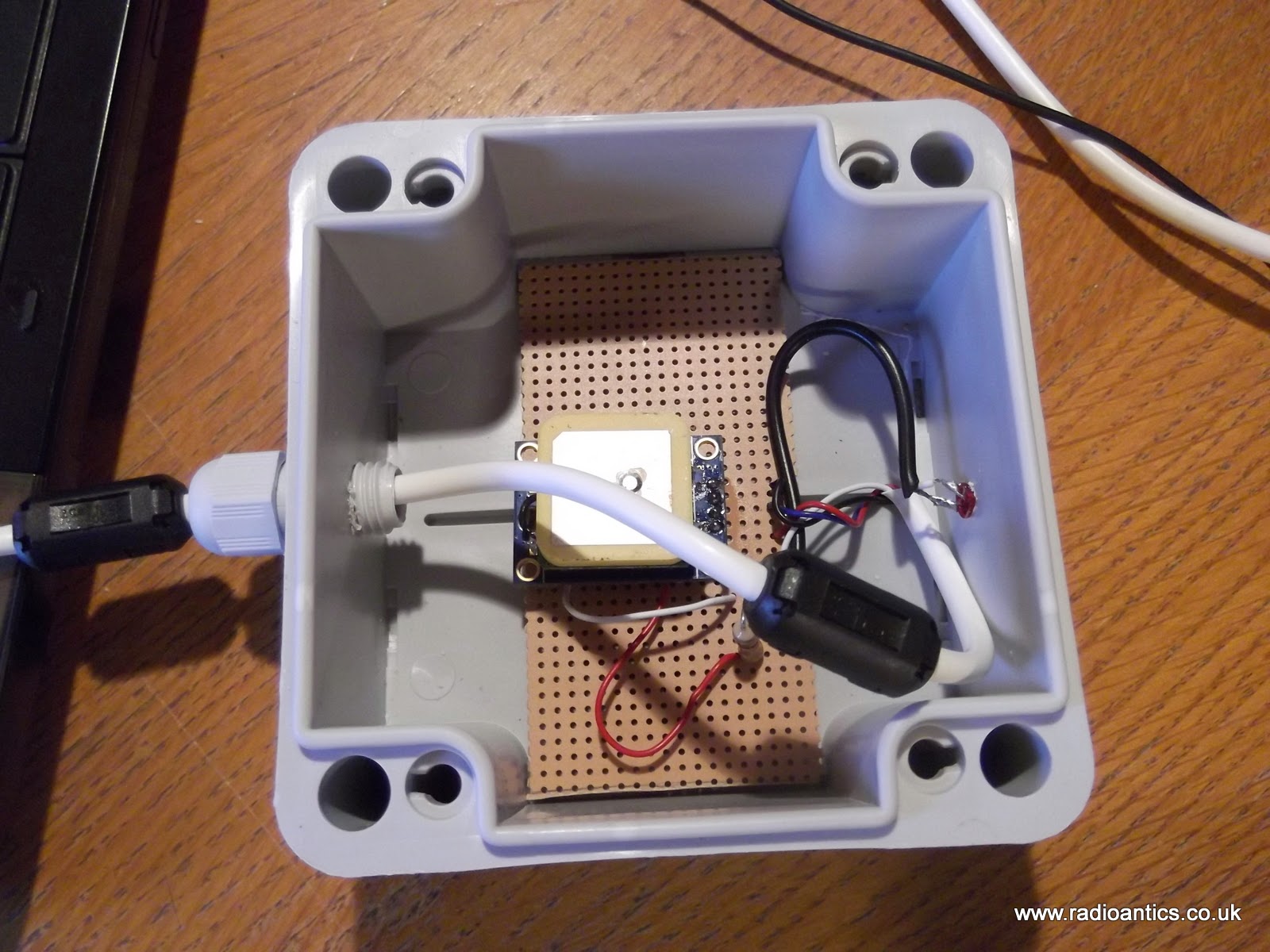
Sourcing an inexpensive weatherproof enclosure (£2) and waterproof cable gland were straightforward enough. I mounted the GPS module on a piece of strip board and replaced the on board LED with one mounted in the enclosure so I easily determine if the GPS had achieved lock, since it only flashes when it has. The LED is sealed with epoxy resin. It should be noted that the outputs of the U-BLOX chip are only rated at 10mA so bear it mind when selecting an LED and calculating the current limiting resistor. The connecting cable is some surplus unscreened alarm cable fitted with a couple of ferrite clamps.
The GPS now has no trouble achieving lock and quickly sets the Ultimate3 clock. Researching the 1PPS problem I hadn't come up with anything definite, as the signal looked okay on the oscilloscope. But I decided to fit a 10K resistor pull up resistor between the 1PPS output and the 3.3V supply on the GPS module. If this actually made the difference I have no idea but the Ulimate3 now successfully calibrates the DDS using the GPS.
At the moment I have configured the beacon to run WSPR and I have been spotted by other operators. Initially I wasn't getting much RF out of the device and it turned out to be a combination of poor connection caused by me not removing the enamel properly on a toroid winding and an iffy antenna connector. Both have been corrected and now get a measurable deflection on the SWR/Power meter. With the additional of a second power amplifier FET it is around 200-250mW.
I purchased the Ultimate3 with a low pass filter for the 40M band and while I have had some European spots the results have been a little disappointing. 40M has turned out to be almost unusable at my QTH due to QRN/M so not sure if that is having an effect, also the antenna I have isn't naturally resonant on 40M so is going through a tuner which will certainly be introducing some losses, without the tuner the FETs get very warm!
With this in mind I have purchased some additional LPFs for the 30M and 20M bands and the LPF relay switching board for the Ultimate 3 so can try/run multiple bands.
Time to play with GPS and Arduino
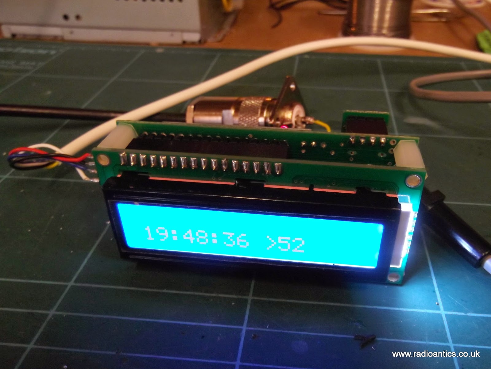
I’ve always enjoyed playing about with time. Accurate time is not really a fascination but I do like a clock to tell the time. The MSF 60khz time signal is one source and I have played about with that system with an Arduino and it works well, when there is a good signal for a whole minute. GPS time has always been a bit of a thing for me because you can set it to UTC and it’ll always show UTC and frankly there are a lot more libraries available to play with. GPS Tiny & GPS Tiny+ are two of those and this evening I ‘forked’ a sketch to use a cheapo off the shelf gps module to tell the time and date on a 16×2 LCD. Nothing spectacular but hey if I can do it then so can anyone. Here’s a short sweet video of it in action (near the window!)
sketch goes a little like this
#include <TinyGPS++.h>
#include <SoftwareSerial.h>
#include <LiquidCrystal.h>
/*
This sample sketch demonstrates the normal use of a TinyGPS++ (TinyGPSPlus) object.
It requires the use of SoftwareSerial, and assumes that you have a
4800-baud serial GPS device hooked up on pins 8(rx) and 9(tx).
*/
static const int RXPin = 8, TXPin = 9;
static const uint32_t GPSBaud = 9600;
// The TinyGPS++ object
TinyGPSPlus gps;
// The serial connection to the GPS device
SoftwareSerial ss(RXPin, TXPin);
// initialize the library with the numbers of the interface pins
LiquidCrystal lcd(12, 11, 5, 4, 3, 2);
void setup()
{
ss.begin(GPSBaud);
lcd.begin(16,2);
lcd.setCursor(1,0);
lcd.print("Tiny GPS+ Time");
delay(3000);
lcd.setCursor(1,2);
lcd.print("by Alex, g7kse");
delay(5000);
lcd.clear();
}
void loop()
{
// This sketch displays information every time a new sentence is correctly encoded.
while (ss.available() > 0)
if (gps.encode(ss.read()))
displayInfo();
if (millis() > 5000 && gps.charsProcessed() < 10)
{
lcd.print("No GPS detected");
for (int positionCounter = 0; positionCounter < 20; positionCounter++) {
while(true);
}
}
}
void displayInfo()
{
lcd.setCursor(4,0);
{
if (gps.time.hour() < 10) lcd.print(F("0"));
lcd.print(gps.time.hour());
lcd.print(F(":"));
if (gps.time.minute() < 10) lcd.print(F("0"));
lcd.print(gps.time.minute());
lcd.print(F(":"));
if (gps.time.second() < 10) lcd.print(F("0"));
lcd.print(gps.time.second());
}
lcd.setCursor(3,2);
{
if (gps.date.day() < 10) lcd.print(F("0"));
lcd.print(gps.date.day());
lcd.print(F("/"));
if (gps.date.month() < 10) lcd.print(F("0"));
lcd.print(gps.date.month());
lcd.print(F("/"));
lcd.print(gps.date.year());
}
}
Cheap GPS module
Most GPS devices have a limit on the altitude they work at, normally 60,000 feet or less. This is a legacy of the now defunct CoCom (Coordinating Committee for Multilateral Export Controls) restrictions. For my HAB project this restriction needs to be disabled and the GPS must be switched into 'flight mode' In the HAB community the favoured devices are made by U-BLOX
Therefore when I was sourcing a GPS I had search specifically for a inexpensive device using a U-BLOX.
 s s |
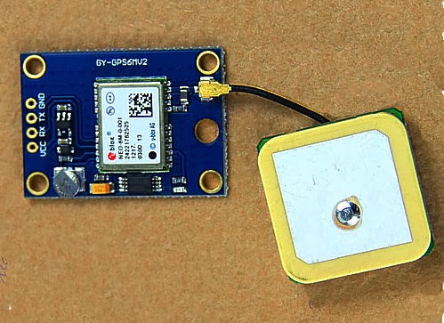
| The GY-GPS6MV2 as supplied |
It is also available from domestic suppliers but often at a much more inflated price, but you don't have to wait several weeks for them to be delivered.
There are many other GPS modules available but this module seems to be one of the cheapest available. it is often listed as a NEO6MV2 GPS Module Aircraft Flight Controller.
The module consists of a small PCB 25mm x 35 mm size with a separate ceramic antenna connected by a small lead which is 25mm x 25mm in size. The Antenna is quite heavy and isn't suited to Pico HAB payloads but for other uses is more than satisfactory.
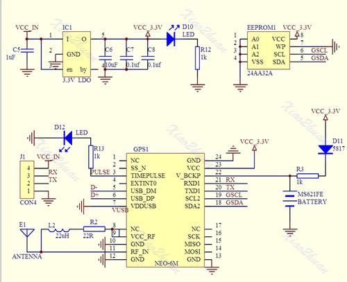
On the board is a small button-cell battery to provide backup to the GPS chip and a small EEPROM connected to the GPS chip which I believe can store configuration(s). I haven't used it myself just using the module in it's default set up at the moment. For a schematic click here
The board has four connectors VCC, GND, TX (Transmit) and RX (Receive) and can be powered by the 5V supply on Arduino boards since it has a small regulator to provide the 3.3V needed.
In most projects all that is required is data out of the GPS. The GPS TX (data out) being connected directly to the microcontrollers RX (data in) The (0V and 3.3V) level shift of the signal is compatible with the TTL input of the microcontroller.
The GPS by default will start up and output standard NMEA sentences at 9600 Baud, until GPS position lock is achieved the NMEA sentences won't have a long/lat location. The module also has an LED which will start flashing once a lock is achieved.
There is no direct connection for the highly accurate 1PPS (pulse per second) signal that can be used for frequency calibration, but the flashing LED is driven by pin 3 of the GPS module which is the 1PPS (pulse per second) signal required.
The 1PSS signal, like the TX is either 0V and 3.3V, in order to use it a small lead will need to be soldered onto the board, either directly onto Pin3 of the GPS chip, or alternatively on to the small current limiting resistor used by the LED, as indicated below.
 |
| Showing the GPS 1pps points |


