Posts Tagged ‘GPS’
 QRP Labs kits
Recently I enjoyed a rare day out at the National Hamfest in far away Lincolnshire. Whilst I was subjected to a culinary travesty with a plate of something advertised as lasagne for an exorbitant price that bore little resemblance to the traditional dish. It was the only low point.
Meeting with a few fellow hams was great (no names mentioned but a couple of the were Lids) there was also really short conversation with Hans Summers, G0UPL who some might know through his kits and bits at QRP Labs. He was being mobbed by ‘gentlemen’ who were hell bent on smashing my knees and shins with their walking aids as a way to push me out of the way. I’ve bought a few bits and pieces from him in the past and really enjoyed building them. Most of which I have done with ease but not really understood exactly what is going on in every case. The most recent I bought a year or so ago at the Norbreck rally. The signal generator / vfo kit.
This time around it was the GPS receiver. I still don’t really know how the circuit works but it is something that I should really get my head around.
How am I going to do that? well one thing would be to ask the original designer. The other way is to increase my knowledge and chances of getting a better understanding of other designs by trying to work out how they work rather than to just build them and rarely use them. I’m doing a bit of both. I had a great chat with Hans but have completely forgotten what we spoke about owing to the beating I was getting. It was general chit chat rather than mind blowing stuff. Luckily there is a group on Groups.io that help to fill in the gaps.
The plan is to combine the 2 to make a natty clock/sig gen. The plan is currently working. Here is the evidence.

So what I hear you cry. You can follow some instructions. True. But I also flashed the Atmega with an upgraded .hex file using Xloader (a nice utility I found). Not done that before. This brings the score to learning stuff to 2. Eh? what else did I learn? Well I read all the docs and found out that you can combine inputs on an AND gate and do some level conversion. Just don’t test me on it! Perhaps not leaps in terms of learning but now I am slightly more competent.
Onward and upward people. Onward and upward.
Yet another Arduino clock
Does the world need more Arduino clocks? Maybe not. But I needed another Arduino project as I had made a K3NG morse keyer. I love this keyer because it is unique in supporting a display where you can see what you send.
But I wasn’t using the morse keyer all the time, so I wanted the hardware to serve two purposes. That’s the excuse for also making a clock. Its main features are:
- Controlled by a GPS module outputting data over an RS232 serial interface, and handled with the TinyGPS++ library
- Shows raw GPS data such as UTC time and date, position, altitude, and number of satellitess
- Shows derived GPS data such as 6-digit locator
- Finds local time and handles daylight saving automatically using the Timezone library
- Finds local sunset and sunrise, either actual value, or civil, nautical, or astronomical. The library is Sunrise.
- The clock also gives local solar height based on the Sunpos library from the K3NG rotator controller.
- Finally, the clock also provides the lunar phase based on ideas found here and using a reference new moon on 11 November 2015, 11:47 (UNIX time 1447264020)
 |
Local time, solar and lunar state Line 1: Local day, date, time Line 2: Sunrise, maximum solar elevation (actual solar angle during the day), sunset Line 3: Civil dawn, local time at maximum solar elevation, civil dusk Line 4: Lunar phase, arrow showing that it is rising, days since new moon |

 |
| UTC and position display Line 1: UTC time, locator Line 3: latitude, longitude Line 4: Altitude, number of GPS satellites |
 |
| Dual time display with local time, UTC time, and locator |
The post “Yet another Arduino clock” first appeared on the LA3ZA Radio & Electronics Blog.
Yet another Arduino clock
Does the world need more Arduino clocks? Maybe not.
But I needed another Arduino project as I had made a K3NG morse keyer. I love this keyer because it is unique in supporting a display where you can see what you send. But I wasn’t using the morse keyer all the time, so I wanted the hardware to serve two purposes. That’s the excuse for also making a clock.
Its main features are:
- Controlled by a GPS module outputting data over an RS232 serial interface, and handled with the TinyGPS++ library
- Shows raw GPS data such as UTC time and date, position, altitude, and number of satellitess
- Shows derived GPS data such as 6-digit locator
- Finds local time and handles daylight saving automatically using the Timezone library
- Finds local sunset and sunrise, either actual value, or civil, nautical, or astronomical. The library is Sunrise.
- The clock also gives local solar height based on the Sunpos library from the K3NG rotator controller.
- Finally, the clock also provides the lunar phase based on ideas found here and using a reference new moon on 11 November 2015, 11:47 (UNIX time 1447264020)
|
Local time, solar and lunar state Line 1: Local day, date, time Line 2: Sunrise, maximum solar elevation (actual solar angle during the day), sunset Line 3: Civil dawn, local time at maximum solar elevation, civil dusk Line 4: Lunar phase, arrow showing that it is rising, days since new moon |
|
| UTC and position display Line 1: UTC time, locator Line 3: latitude, longitude Line 4: Altitude, number of GPS satellites |
|
| Dual time display with local time, UTC time, and locator |
The post “Yet another Arduino clock” first appeared on the LA3ZA Radio & Electronics Blog.
Improved GPS reception with a ground plane

My poor-man’s 10 MHz reference based on the Ublox Neo-7M GPS module didn’t always receive GPS satellites reliably enough. Since I rely on reception indoors, conditions were sometimes too marginal to lock the oscillator output to 10 MHz. Inspired by the QRPlabs GPS module of Hans Summers (G0UPL) with its large 6 x 6 cm PCB groundplane, I therefore decided to do something similar.
It definitely helped make indoors reception in my shack much more reliable. The first picture shows the unit with the 8.5 x 6.5 cm single-sided PCB ground plane attached with double-sided tape. The picture below shows it prior to adding the ground plane. I also added a small LED to the right so that I could see from the outside whether the GPS locks properly.
This post is a continuation of these other posts about the 10 MHz reference:
- Just good enough 10 MHz reference (3 Oct 2015)
- Better with SMA (15 Oct 2015)
- Curing amnesia in the 10 MHz GPS reference (19 Nov 2015)
Improved GPS reception with a ground plane
My poor-man’s 10 MHz reference based on the Ublox Neo-7M GPS module didn’t always receive GPS satellites. Since I rely on reception indoors, conditions were sometimes too marginal to lock the oscillator output to 10 MHz. Inspired by the QRPlabs GPS module of Hans Summers (G0UPL) with its large 6 x 6 cm PCB groundplane, I therefore decided to do something similar.
The first picture shows the unit with the 8.5 x 6.5 cm single-sided PCB ground plane attached with double-sided tape. It definitely helped make indoors reception in my shack much more reliable. In addition to the improved conditions for the patch antenna, it probably helps too that the antenna now is shielded from the digital circuitry of the GPS module, the 10 MHz pulse shaper, and the USB interface. I also added a small LED to the right so that I could see from the outside whether the GPS locks properly.
The second picture shows the interior prior to adding the ground plane.
This post is a continuation of these other posts about the 10 MHz reference:
- Just good enough 10 MHz reference (3 Oct 2015)
- Better with SMA (15 Oct 2015)
- Curing amnesia in the 10 MHz GPS reference (19 Nov 2015)
Curing amnesia on the 10 MHz GPS reference
 |
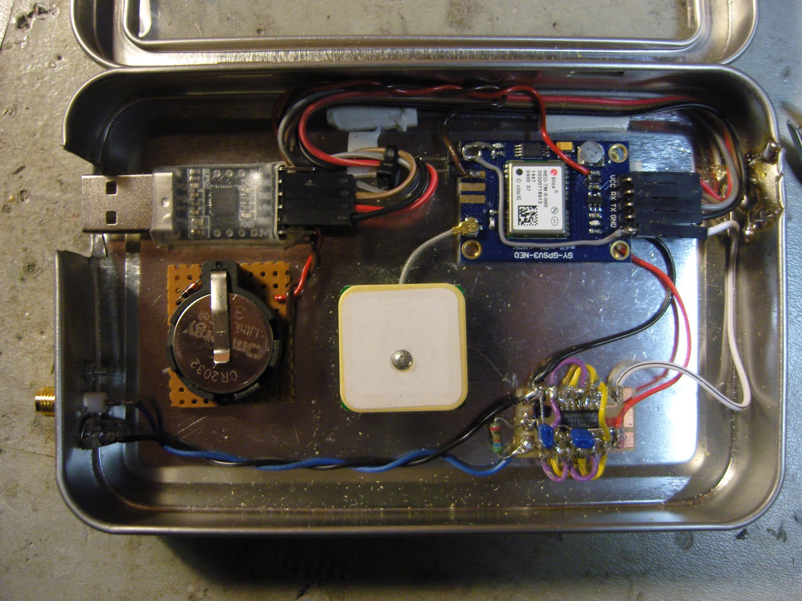
| Just good enough 10 MHz GPS reference with u blox Neo-7M GPS module to the upper right, 10 MHz output buffer lower right, USB interface to the upper left, CR2032 lithium battery center left, GPS antenna in the center, and SMA output connector lower left. |
My just good enough 10 MHz GPS reference which drives the external clock input on my Elecraft K3 kept losing its configuration if power was off for a day or so. I have therefore fitted a CR2032 3V lithium battery as seen to the left in this image.
It is connected in series with a 1N4148 diode in order to prevent attempts at charging the lithium cell. The connection goes to pin 22 (V_BCKP) as described by G4ZFQ on his website. The diode is visible to the upper left of the battery.
With this, I consider the 10 MHz reference to be finished.
Earlier related posts:
Curing amnesia in the 10 MHz GPS reference
|
| Just good enough 10 MHz GPS reference with u blox Neo-7M GPS module to the upper right, 10 MHz output buffer lower right, USB interface to the upper left, CR2032 lithium battery center left, GPS antenna in the center, and SMA output connector lower left. |
My “just good enough 10 MHz GPS reference” which drives the external clock input on my Elecraft K3 kept losing its configuration if power was off for a day or so. I have therefore fitted a CR2032 3V lithium battery as seen to the left in this image.
It is connected in series with a 1N4148 diode in order to prevent attempts at charging the lithium cell. The connection goes to pin 22 (V_BCKP) as described by G4ZFQ on his website. The diode is visible to the upper left of the battery.
With this, I consider the 10 MHz reference to be finished.
Other related posts:


