Posts Tagged ‘Arduino’
 HAB Talks
Last week I gave two talks and demonstrations at local radio societies on High Altitude Ballooning in the UK and how to track them.
The first was at South Kesteven ARS (SKARS) the club I am a member of. The second was at Spalding and District ARS (SDARS)
This was an updated version of the talk I gave last year at SKARS. Since then I have started work on my own tracker NERD-1. Sadly development has stalled and is still only at the prototype stage (NERDTEST) but I was able to use it to demonstrate reception and tracking using the UKHAS Habitat system spacenear.us/tracker
The SDARS venue had a projector and a decent WiFi Internet connection which allowed me to demonstrate how to set up DL-FLDIGI for a ground station and NERDTEST being received and both showing up on the map in real time.
My original PowerPoint presentation has been given a total makeover and I has included some videos of Felix Baumgartner, Dave Akerman’s Babbage Teddy Bear and wacky chef Heston Blumenthal's ‘Spud-in-space’ feature from his new television program.
To show a real tracker Steve Smith (G0TDJ) of Project Hab had been kind enough to loan me his VAYU-NTX unit.

I am not the most confident of people when it comes to public interaction and it was encouraging to see people genuinely interested in what I was talking about and keen to have a look and I have had some very nice feedback.
Thanks @nerdsville for an excellent talk on High Altitude Balloons and telemetry, look forward to your launch. pic.twitter.com/H8AevMNQ13
— Spalding DARS (@SDARS) May 16, 2014
Excellent talk at Club tonight by @nerdsville on high altitude balloons and radio data. Andrew knows his subject and enthusiasm infectious.
— Jim Scott G0HGH (@photoimagery) May 16, 2014
Giving these talks has spurred me to pull my finger out and get on with actually flying something and finishing the payload!
Another mothballed project is my Ultimate3 beacon kit, still being only a Foundation licence means I cannot use it to transmit but that may be about to change as tomorrow I am sitting my Intermediate exam which will allow me to properly experiment with transmitters. The exam was arranged through SKARS by Chairman Nigel Booth and the date came through a little sooner than I was expecting so perhaps not quite as prepared as I really should be, but with a decent electronics background and some quick revision it should be fine....
My operating has been largely limited to the UKAC VHF contests, setting aside a few hours per week is manageable and my results are gradually improving, even getting some complements on my operating.
Two weeks ago I was able to attend the local Dambusters Hamfest at Thorpe Camp and managed to pick up a decent rotator, this has proved invaluable for the UKAC as I don’t have to keep going outside the shack to turn the antenna.
Now if I hear someone calling CQ and can monitor a QSO to get the locator and the bearing a quick turn of the dial and I have a better chance. The program I use is BD_2004 from W1GHZ, running in console window it is a simple case of setting up your own locator and then entering other locators the bearing and distance are given.
As well as the weeknight UKAC there have been a couple of weekend VHF contests, I managed a couple of hours this weekend on the RSGB 144MHz May Contest and I had the best DX ever and nearly every QSO was in a new locator square!

I wasn’t able to spend more time on the contest as we took the dogs on a sponsored dog walk on Sunday in aid of the local hospice and on Saturday I attended the British Astronomical Association, Radio Astronomy Group General Meeting at the National Space Centre.
The notion of amateur Radio Astronomy is something that has fascinated me, up to now the only dabbling I have done has been with meteor detection using reflections from the Graves space radar (blog entry). This year some of the talks dealt with using RTL-SDR and Arduino/Raspberry PI in low-cost observation. Also at the meeting was a number of demonstrations and stands from other projects we I was able to garner a great deal of useful information.
Being able to detect ‘Hydrogen-Line’ emissions to map the Galactic plane using a FUNCube or RTL-SDR dongle is astonishing, not to mention low cost VLF receivers to detect Sudden Ionospheric Disturbances SIDs and magnetometers to measure the effect of the solar wind on the earth’s magnetic field!
It is all on the to do list, but it was a great day with some really fascinating talks and some exciting plans by the group. It was a shame I had to leave earlier than I wanted as I did miss some of the later presentations.
Anyway best get an early night!
BEC Fab Lab
Not strictly Ham Radio but worthy of a mention, I dropped into the BEC Fab Lab today to talk to them about laser cutting some cases for our clubs summer build. We’ll be doing something simple this year ( the Hans Summers, GoUPL Ultimate QRSS kit v3 – mine is on order) and I’m keen to tie in what we do with them as we could use their services and they could potentially open up amateur radio to a wider audience.
I was really impressed and can’t wait to get my hands on their 3d printer, I just don’t know what I ought to print…perhaps a callsign badge
Non-English display for the K3NG Arduino Morse keyer
German, Swedish, Danish, Norwegian, Finnish, and some Spanish characters in the display are now supported by the K3NG Arduino Open Source Morse keyer. I have worked with OZ1JHM, Hjalmar and K3NG, Anthony, in order to implement this using the 8 custom-designed characters of the LCD display (based on the Hitachi HD44780). This should satisfy the call I had for such support here on this blog last year: Which non-English Morse characters are the most important ones?
Here are examples using the phonetic alphabets of these languages.
- For Norwegians and Danes – Æ, Ø, Å:
- For Swedes and Finns. But if you are not, then perhaps you still need to send your shopping list of IKEA products in Morse? – Å, Ä, Ö
- For Germans – Ä, Ö, Ü:
|
|


|
|


 |
| German: Ärger Ökonom Übermut |
 |
| España |
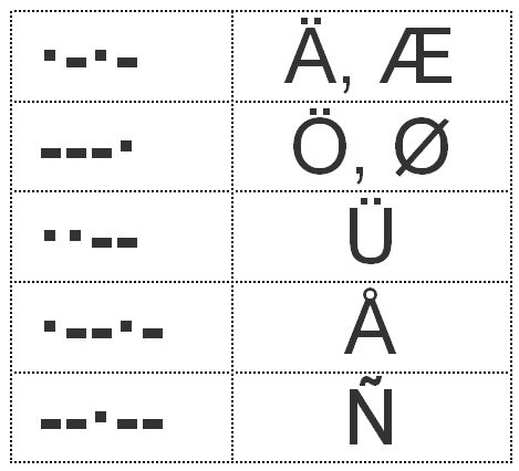
The most likely combinations of characters are:
- Æ, Ø, Å, Ü, Ñ for Danish/Norwegian.
- Ä, Ö, Å, Ü, Ñ for German/Swedish/Finnish.
It should be noted that Ö=Ø and Ä=Æ when it comes to Morse code (and meaning).
It is also possible to support the CH which has its own Morse code (—-), but so far I haven’t been able to find a symbol that represents this letter. Neither should it be much of a problem to support other letters also, such as French accents and the C cedilla (À, È, É, Ç). All it takes is to generate a bit pattern using an editor such as the one provided here and replace some of the above characters.
I am very happy for the collaboration that took place to make this possible and not the least to Anthony, K3NG for making his work available and his willingness to accept ideas for changes and improvements. For the time being, this feature is in the beta version, but hopefully it will eventually find its way into the official version. It can be enabled by uncommenting:
- #define OPTION_NON_ENGLISH_EXTENSIONS
- #define OPTION_DISPLAY_NON_ENGLISH_EXTENSIONS
Cheap GPS module
Most GPS devices have a limit on the altitude they work at, normally 60,000 feet or less. This is a legacy of the now defunct CoCom (Coordinating Committee for Multilateral Export Controls) restrictions. For my HAB project this restriction needs to be disabled and the GPS must be switched into 'flight mode' In the HAB community the favoured devices are made by U-BLOX
Therefore when I was sourcing a GPS I had search specifically for a inexpensive device using a U-BLOX.
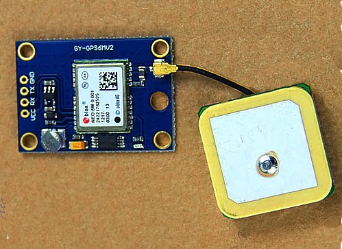 s s |
| The GY-GPS6MV2 as supplied |
It is also available from domestic suppliers but often at a much more inflated price, but you don't have to wait several weeks for them to be delivered.
There are many other GPS modules available but this module seems to be one of the cheapest available. it is often listed as a NEO6MV2 GPS Module Aircraft Flight Controller.
The module consists of a small PCB 25mm x 35 mm size with a separate ceramic antenna connected by a small lead which is 25mm x 25mm in size. The Antenna is quite heavy and isn't suited to Pico HAB payloads but for other uses is more than satisfactory.
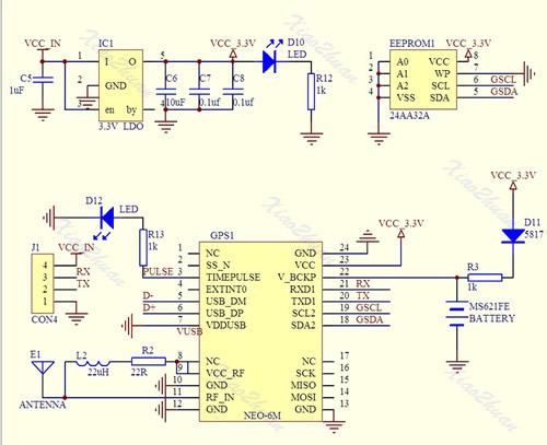
On the board is a small button-cell battery to provide backup to the GPS chip and a small EEPROM connected to the GPS chip which I believe can store configuration(s). I haven't used it myself just using the module in it's default set up at the moment. For a schematic click here
The board has four connectors VCC, GND, TX (Transmit) and RX (Receive) and can be powered by the 5V supply on Arduino boards since it has a small regulator to provide the 3.3V needed.
In most projects all that is required is data out of the GPS. The GPS TX (data out) being connected directly to the microcontrollers RX (data in) The (0V and 3.3V) level shift of the signal is compatible with the TTL input of the microcontroller.
The GPS by default will start up and output standard NMEA sentences at 9600 Baud, until GPS position lock is achieved the NMEA sentences won't have a long/lat location. The module also has an LED which will start flashing once a lock is achieved.
There is no direct connection for the highly accurate 1PPS (pulse per second) signal that can be used for frequency calibration, but the flashing LED is driven by pin 3 of the GPS module which is the 1PPS (pulse per second) signal required.
The 1PSS signal, like the TX is either 0V and 3.3V, in order to use it a small lead will need to be soldered onto the board, either directly onto Pin3 of the GPS chip, or alternatively on to the small current limiting resistor used by the LED, as indicated below.
 |
| Showing the GPS 1pps points |
Ultimate3 QRSS Beacon kit built!
My current licence restrictions prevent me using anything home-brew for transmitting except for commercial kits. So I ordered an Ultimate3 QRSS beacon kit from Hans Summers (G0UPL) thinking that it would be okay. I subsequently learned that any commercially available kit must satisfy IR 2028 which is all a bit vague and unclear but sadly I don't believe this particular kit does.
All was not lost, building this kit should more than satisfy one of the practical assessments of the intermediate examination, which will get me around this problem.
The Ultimate3 kit is extremely popular and so I had to wait a little for delivery and it arrived on Friday. After the last few weekends of non-radio activities I had planned to get my antennas backup and do some proper operating. Like many people I had been forced to take everything down due to the barrage of storms and high winds the UK has been experiencing recently.
 |
| A tidy workbench |
Saturday saw no let up in the wind, so I decided to spend a few hours building the kit instead.
The instructions were extremely clear and straight forward and soon had it built up, though it is high time I invested in new soldering station. I have a basic Antex 25W iron. I cannot remember exactly when I brought it but it is well over 10 years ago. It was more than adequate to build this kit and for soldering connectors but I could do with something adjustable and more comfortable.
 |
| Taking shape |
I also made the mistake of not scraping the enamel off the toroid wire and tried the heat it and bubble it off method, except I think my iron just isn't hot enough so ended up using a piece of wire wool to remove the enamel.
Lessons learned I soon had the other three toroids correctly wound and wire prepared for the low-pass filter board.
 |
| Close up of the LPF |
 |
| All built |
 |
| It works! |
 |
| Setting it up |
Pressing the button I occasionally got some random characters and a flashing cursor! I de-soldered the GPS and still nothing. I suspected the display was faulty but trying it on the HAB prototype board confirmed it was okay. I checked the display connector continuity and everything appeared okay.
Out with the oscilloscope I started probing, everything checked out. Crystal was oscillating and data pulses on the display control lines. Then I checked the supply pin on the display and it was only reading 4.1V, this under-voltage would explain the odd display behaviour.
PSU output was 5V, micro-controller was 5V, DDS module had 5V. All very puzzling till I removed the DDS module and spotted a discoloured track on the PCB, touching it with a screwdriver and the lacquer fell away revealing a tell tale scorch mark, somehow I had made a nice resistor!
 |
| Burnt track to right of micro-controller |
What caused it? Checking the de-soldered GPS connecting wire I spotted a stray single strand of wire on the ground wire. I suspect this must have shorted to the adjacent 5V line and since I was using a nice beefy ex-PC PSU as a bench supply it had popped the track without the hint of a flicker. The GPS has been rewired properly and is working nicely, now to connect a dummy load and experiment some more.
Sunday was a lovely day, wind dropped so antennas have been put back up and I took the opportunity to tidy up the installation a bit. I also dug out an old fibreglass pole to put the M0CVO HW-20HP back up. I didn't get to do any operating in the end as by the time I had done this and made up a couple of decent patch leads it was time for roast beef and all the trimmings and an evening in front of the TV.
 |
| The HW-20HP back up |
This weeks learning
So far this week I have learnt that aligning parts in Google Sketchup isn’t as easy as it is in something like Solidworks. Still for a freebie programme I’m not going to complain.
Progress on the rotator project is slow, mainly because of the usual lack of time. But at least the idea is cemented in my head and now its just a case of doing the mechanical design and then hooking everything up. Below is a rough draft of the proposed Az / El arrangement for the clankies amongst us. I’ll complete the design either myself in a huge amount of hours or, more likely ask one of the CAD jockeys at work to fix it in a matter of seconds.

With this arrangement it should not be complex to either fabricate, buy or 3D print parts to suit. The latter is a preference as then the model can then be used by anyone to get parts made either as laser cut solids or 3D prints.
The main parts will be 2 off nema 17 steppers, gears from actobotics (This may need to be adjusted to slow the steppers down sufficiently) and that nice radio artisan / K3NG chaps code with Anthony, M0UPU’s board.
Onwards and upwards
Arduino Rotator
The little project I have to homebrew an Azimuth and Elevation rotator has moved on a little. After spending countless hours researching the project I came across a couple of really useful resources. Firstly the Radio Artisan website has simply done the hard stuff with the codes and secondly Anthony Stirk, M0UPU has made a shield / board for easy interfacing.
I’ve ordered a board and will see what I can do with it once it arrives. Next weekend is SOS Radio Week so I’ll be hamming it up at St Bees Lifeboat station so I doubt I’ll get a chance to do anything but we’ll see.


