Posts Tagged ‘Arduino’
 Just a quickie
Nice to see that SatNOGS won the hackaday prize this evening. A little sad that PortableSDR didn’t win as well. They both prove that Ham Radio is alive and kicking and has a very well rooted place in the 21st century……As if it was ever in doubt

Pinched from hackaday.com
SatNOGS
I remember reading something about this on the Southgate ARC news a while ago. When I tried to find it I couldn’t. Thanks to Hackaday.io I found it again.
So what is it. The website has some big ideas on it but, to me it is a homebrew, simple Az El rotator using open source software and 3D printed parts. Something that, funding willing, I will be able to do over the winter. Info on availability seems a bit scarce but I’ve emailed regarding PCB’s.
Here’s a few links and a video
New gadget measures negative resistance
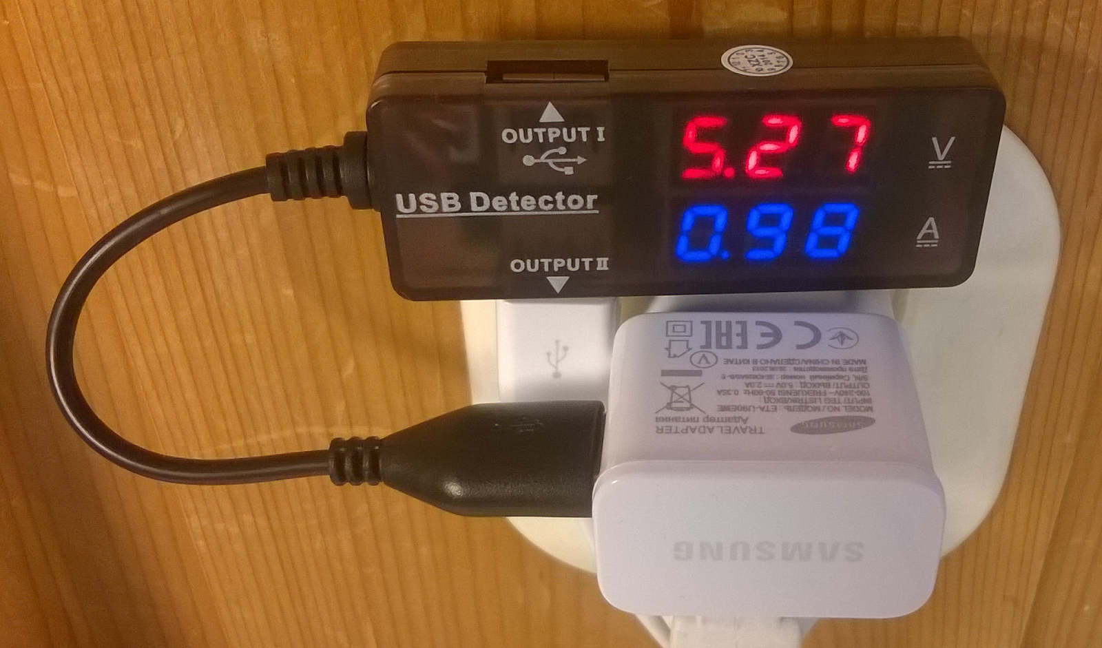
If you are like me, you appreciate electronic gadgets with dials and displays. So when I discovered this “USB detector”, I thought to myself that I really always wanted to know the voltage as well as the current consumption of my USB devices. And since it is more or less impossible to connect a multimeter, this is exactly what I need.
The device fully satisfied my curiosity. Actually one surprising result was that the charger for my Samsung Galaxy Note 8 has a negative output resistance.

With a load it outputs 5.27 Volts as shown in the top image. Usually one expects the voltage to increase when the load is removed. But for this charger the voltage dropped instead to 5.13 Volts (second image). That should mean that there is the equivalent of a series resistance of (5.13-5.27)/0.98 which is about -0.14 Ohm.
I measured other chargers also, without finding a negative output resistance, so it seems as if it applies to this particular charger only. Out of curiosity, I also measured the current consumption of my Arduino Mega to 0.08 A without any shields connects.
The unit has two outputs which are different from each other. Output 1 is a fully functional USB port, while output 2 only connects DC power. What is that good for? Well, the epanoroma blog opened my eyes to the utility of this. If you charge your phone at some public place, then this feature isolates the data port of your phone. That may protect you from being hacked.
So there you see. The €5.13 were well spent and I even learnt something new by giving in to the temptation to click “Buy It Now” on Ebay.
But why does the Samsung charger have what amounts to a negative output resistance, is it by design or by accident?
Grantham ARC HAB Talk
This follows on from the South Kesteven ARS (SKARS) and the Spalding and District ARS (SDARS) talks I gave in May
It was very well attended with a large number of GARC members turning out. It was a case of everyone going in at the same time once the venues key holder turned up and I initially got a little stressed as I hurriedly tried to get everything set up while everyone sat patiently waiting.
 |
| Picture by Kevin Burton |
The first issue I had was the projector seemed to be limited to just 800x600 pixels, which was fine for the PowerPoint presentation but for demonstrating reception using a RTL-SDR with SDRSharp and decoding using DL-FLDIGI and the UKHAS Habitat tracking system spacenear.us/tracker the lack of screen space was a problem, DL-FLDIGI couldn't be shrunk down to fit, so there was a lot of scrolling about!
The second issue was the venues wi-fi connection, my laptop stubbornly refused to connect to it (I wished I'd taken a ThinkPad laptop I have instead of the one I did as it has a better wi-fi adapter) so was forced to use my mobile phone as a tethered hotspot - while it worked the connection was painfully slow.
Despite these issues I was able to give the presentation about the HAB community and the technology. It contains a lot of information to digest but there is some light relief with its videos of Felix Baumgartner, Dave Akerman’s Babbage Teddy Bear free fall and wacky chef Heston Blumenthal's ‘Spud-in-space’ feature from his recent television program.
I demonstrated Project Hab's VAYU-NTX tracker and thanks again to Steve Smith (G0TDJ) for its loan.

I ran my own prototype tracker (NERDTEST) which I had updated to simulate a local flight, the transmission, reception, decoding and uploading to the UKHAS Habitat system was completely genuine, both using SDR and a traditional radio (Alinco DX-10) hooked up to the sound card. The only thing fictitious were the GPS coordinates and altitude. (A programming error in the first version of this simulator had the balloon travelling at near 10km/s, thankfully I had corrected it to something more realistic)
The poor internet connection cause issues with spacenear.us/tracker but was able to use Phil Crump's (M0DNY) version at at habmap.philcrump.co.uk to demonstrate the real time map tracking.
Checking the spacenear.us map this morning and the receiver station at the club house and the demo flight could still be seen - it was programmed to take off from a nearby high point!
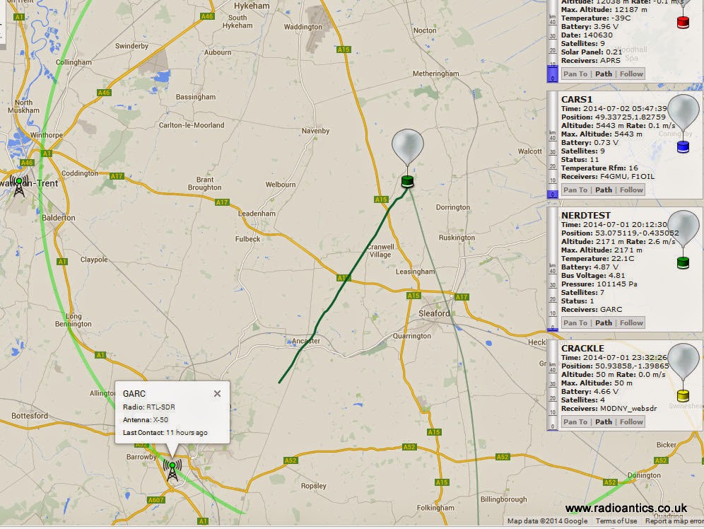
By lucky coincidence Chris Stubbs (M6EDF) had launched a balloon CARS-1 from the Chelmsford Amateur Radio Society meeting at Oaklands Museum where he was giving a talk and demonstration at the same time as my talk, so I was able to show how multiple receiver stations were tracking a real flight.
I was also able to demonstrate SSDV image decoding using some recorded SDR files of the HiPi flight
I thought I had overloaded the attendees with too much information, lots of references to Arduino, Raspberry PIs, SDR, dongles, GPS could be quite daunting to the uninitiated but again feedback has been very positive. Grantham Amateur Radio Club on Facebook
Now I just to sort out doing a proper flight!
Coding for the challenged
Ever since the dawn of time coding has been a foreign language to me. I pick up bits and pieces but largely it gets forgotten or lost.
Tonights issue is about interrupts and debouncing buttons. What better thing to do whilst listening to the 6m white noise contest (also known as vhf from my qth).
The idea is simple. I made a shack clock from a gps and an arduino. I made it tell the time, tell me the position I’m in (no I don’t mean like that) an calculate the locator square. Now then all I want to do is link these together with a simple button press. Press the button and it changes from one function to the next.
Holy arduino, this isn’t straightforward at all. Buttons need debouncing and interrupts don’t like this or that. I feel a long development time in my future…still there’s not much on 6m and 2 contacts in the first hour isn’t going to win me any awards.
Temperature compensation for an Arduino ultrasonic distance sensor
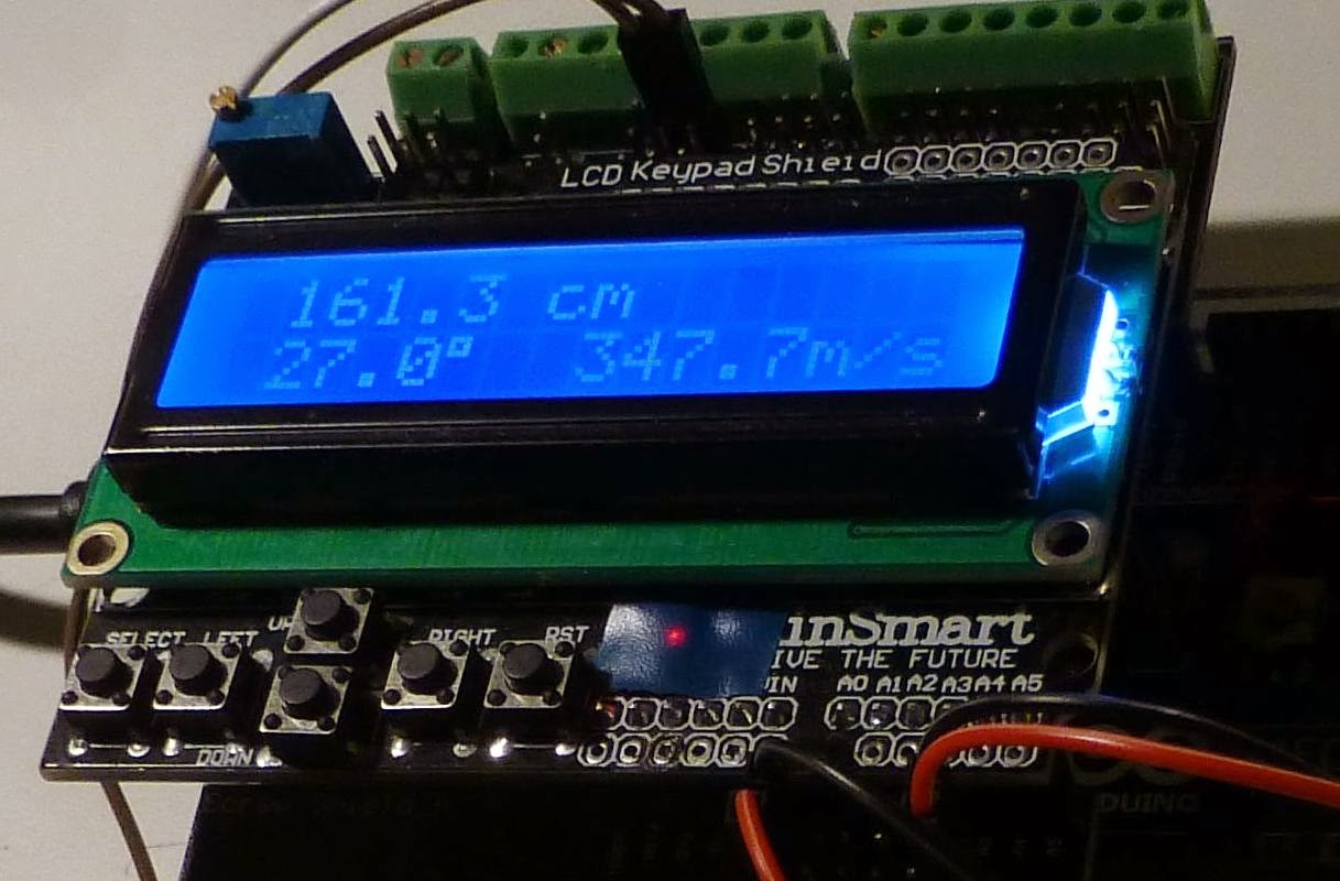 |
161.3 cm 27.0° 347.7 m/s |
Ultrasonic distance sensors can find the range out to 2-4 meters and are popular in e.g. robotics. Here I look at how the accuracy can be improved by compensating for the variation of speed of sound with temperature. It actually varies quite a lot in air and around 0 C it is:
c = 331.3 + 0.606 * T
where c is in m/s and T is in C. The formula is good to up to at least +/-30 C. There is also a dependence of humidity, but as it is so small it is neglected here.
The equation can be analyzed for sensitivity (a little bit of differentation, you know). The result is that a two-way range measurement creates an error of 1.8 mm/C/m. That means that with a 4 degree C error, the deviation will be 14.4 mm at a range of 2 meters. Not a lot, but more than the wavelength which is 9 mm at 40 kHz. Considering how easy it is to compensate for, then why not give it a try?

I have tested this with the inexpensive HC-SR04, but the compensation is really independent of the type of sensor. First let me analyze a typical example code for this sensor:
- For range in cm the code divides elapsed time in microseconds by 29. That corresponds to c=10,000/29=344.8 m/s. According to the equation above, this is the speed for a temperature of 22.3 C.
- For range in inches it divides elapsed time by 74. That corresponds to c=1,000,000/74 =13513.5 inches/sec =1126 feet/sec or 343.2 m/sec. This boils down to an assumed temperature of 19.6 C. That’s 2.7 degrees lower than the calculation for cm and means that the measurement in inches is lower than that in cm by 2.7*1.8 = 4.9 mm per meter of range.
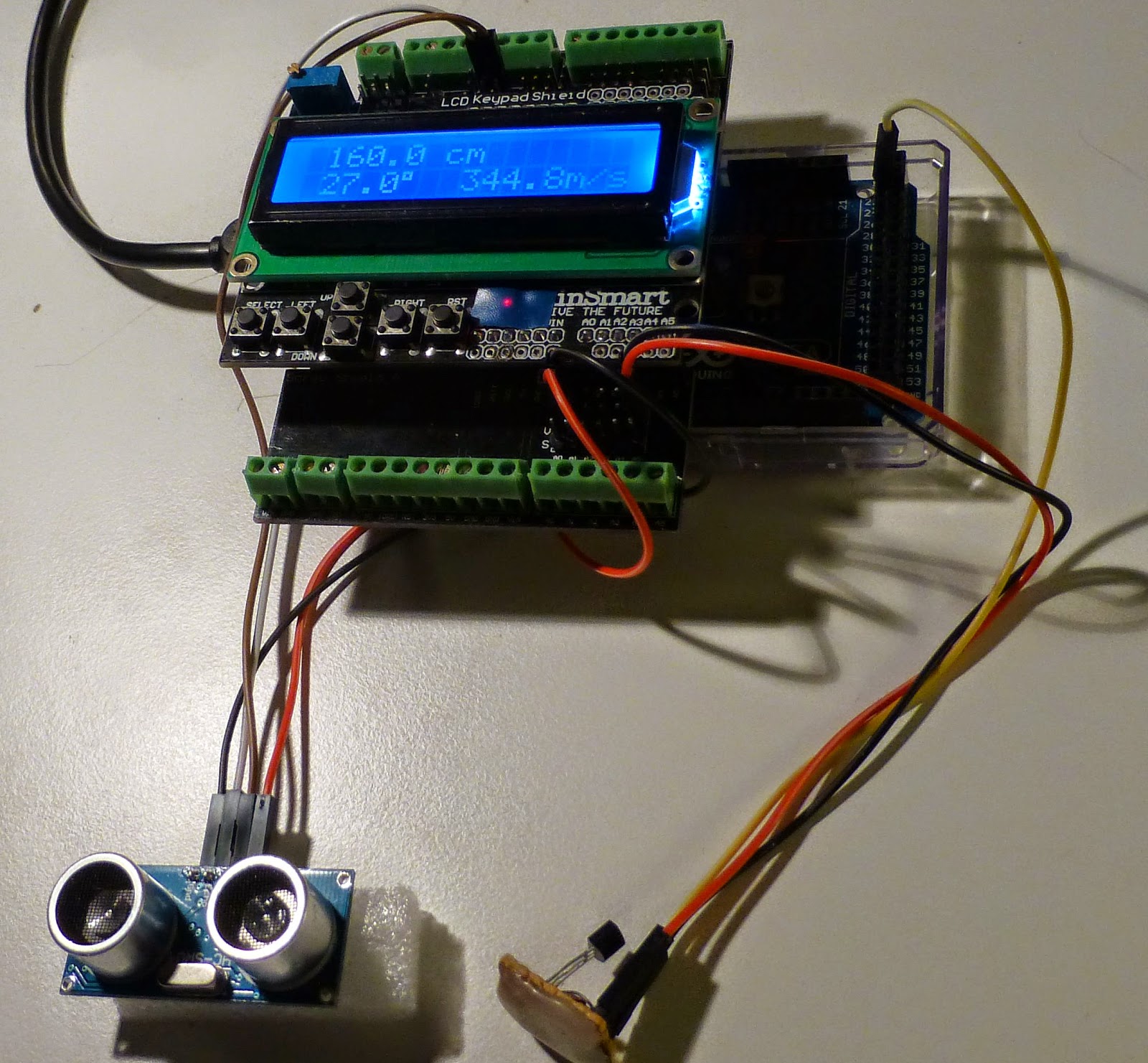 |
| Temperature is 27.0°, but the program doesn’t use that value and assumes instead its standard value of speed of sound of 344.8 m/s and finds 160.0 cm. |
I integrated an HC-SR04 program from Tautvidas Sipavičius with a code from the Arduino playground that uses the DS1820 1-wire temperature sensor (the last program on that page). In the process I had to convert the range estimation from integer to floating point arithmetic. This may give a speed penalty, but at least it runs fine on my Arduino Mega 2560.
The first image in this post shows that at a temperature of 27 C, the speed of sound is 347.7 m/s and the distance from my desk to the ceiling is found to be 161.3 cm. In the picture to the right, I have disabled the temperature compensation so the default velocity of 344.8 m/s is used instead and the estimated distance falls to 160.0 cm.
In the bottom picture, I have detached the 1-wire bus to the temperature sensor, so the program believes it is 0 C, and finds that the range drops to 154.5 cm.
 |
| 154.5 cm 0.0° 331.3 m/s |
Now, the HC-SR04 isn’t the most advanced of sensors. Other sensors may have a more accurate detection circuit that works more reliably and with better repeatability at longer ranges. I should also say that since I admitted a digit behind the decimal point in my code that wasn’t there in the original, my measurements wandered a bit from ping to ping also. In reality, I don’t think the HC-SR04 has much more accuracy than 1 cm. But it may have some potential for improvement as e.g shown here: “Making a better HC-SR04 Echo Locator“.
Combining a better detector with compensation for speed of sound variations with temperature should be what it takes to get the ultimate range sensor.
The Arduino sketch measures the range every 0.1 second and pauses for a second every 10 seconds to measure the temperature. The code is here (formatted with Hilite Me):
/* |
Time to play with GPS and Arduino
I’ve always enjoyed playing about with time. Accurate time is not really a fascination but I do like a clock to tell the time. The MSF 60khz time signal is one source and I have played about with that system with an Arduino and it works well, when there is a good signal for a whole minute. GPS time has always been a bit of a thing for me because you can set it to UTC and it’ll always show UTC and frankly there are a lot more libraries available to play with. GPS Tiny & GPS Tiny+ are two of those and this evening I ‘forked’ a sketch to use a cheapo off the shelf gps module to tell the time and date on a 16×2 LCD. Nothing spectacular but hey if I can do it then so can anyone. Here’s a short sweet video of it in action (near the window!)
sketch goes a little like this
#include <TinyGPS++.h>
#include <SoftwareSerial.h>
#include <LiquidCrystal.h>
/*
This sample sketch demonstrates the normal use of a TinyGPS++ (TinyGPSPlus) object.
It requires the use of SoftwareSerial, and assumes that you have a
4800-baud serial GPS device hooked up on pins 8(rx) and 9(tx).
*/
static const int RXPin = 8, TXPin = 9;
static const uint32_t GPSBaud = 9600;
// The TinyGPS++ object
TinyGPSPlus gps;
// The serial connection to the GPS device
SoftwareSerial ss(RXPin, TXPin);
// initialize the library with the numbers of the interface pins
LiquidCrystal lcd(12, 11, 5, 4, 3, 2);
void setup()
{
ss.begin(GPSBaud);
lcd.begin(16,2);
lcd.setCursor(1,0);
lcd.print("Tiny GPS+ Time");
delay(3000);
lcd.setCursor(1,2);
lcd.print("by Alex, g7kse");
delay(5000);
lcd.clear();
}
void loop()
{
// This sketch displays information every time a new sentence is correctly encoded.
while (ss.available() > 0)
if (gps.encode(ss.read()))
displayInfo();
if (millis() > 5000 && gps.charsProcessed() < 10)
{
lcd.print("No GPS detected");
for (int positionCounter = 0; positionCounter < 20; positionCounter++) {
while(true);
}
}
}
void displayInfo()
{
lcd.setCursor(4,0);
{
if (gps.time.hour() < 10) lcd.print(F("0"));
lcd.print(gps.time.hour());
lcd.print(F(":"));
if (gps.time.minute() < 10) lcd.print(F("0"));
lcd.print(gps.time.minute());
lcd.print(F(":"));
if (gps.time.second() < 10) lcd.print(F("0"));
lcd.print(gps.time.second());
}
lcd.setCursor(3,2);
{
if (gps.date.day() < 10) lcd.print(F("0"));
lcd.print(gps.date.day());
lcd.print(F("/"));
if (gps.date.month() < 10) lcd.print(F("0"));
lcd.print(gps.date.month());
lcd.print(F("/"));
lcd.print(gps.date.year());
}
}


