Posts Tagged ‘Arduino’
 Wrestlemania
Back when I had an easier job I decided that I’d attempt to make a really simple, lightweight rotator that used off the shelf servos or stepper motor’s driven by an Arduino. Either interfaced with a PC or as a stand alone device.
Well, things move when you’re not looking and it seems like my bright idea was also several others, and whilst I’ve been busy not doing anything radio, others have.
I’d managed to buy a couple of servos off eBay and managed to drive them with the standard examples. Although the movement wasn’t as smooth as I’d have liked. Perhaps a couple of large capacitors would have helped but as I didn’t have anything suitable to hand I thought I would have a go anyway.
Well it didn’t work out like that. After spending over an hour installing the Windows 8 drivers (how to turn you off an operating system!) I hooked up the Arduino and wrestled with the servos. Either they are knackered or there’s something missing…..
Time to take a step back and reflect, or buy a few caps
Another Day Another Arduino Project
As I mentioned in passing yesterday I have a number of Arduino based projects buzzing around in my head. One of them is to produce a satellite antenna pointer/indicator.
I have used an Android AR tracking solution before (flaky at best) and can see the relevant information in Orbitron or SatPC32 to know where to point the antenna but it is difficult to see a PC screen when stuck out in the middle of the lawn!
My idea is this, I will make a large tripod to which I can attach appropriate antenna as I need, then during the satellite pass it has indicators to show where to point the antenna manually.
I envisage the azimuth indicator to be a large horizontal circle with 36 LEDs positioned at 10 degree intervals, the elevation will be a quarter circle with 20 LEDs positioned at 5 degree intervals. Then during the pass the appropriate LEDs will light and assuming I keep the antenna aligned to these I should in theory get the best signal... Crazy??
Yes I know I could make or buy an azimuth/elevation rotator, eBay is full of low speed high torque geared DC motors with auto-stop/hold and numerous software solutions exist to drive them but this would require a bit more engineering and isn't something I can easily fabricate at the moment. My contraption would be much more rustic being made of rough cut timber!
Bright LEDs are ridiculously cheap and controlling this number from the Arduino will require the use of multiplexer drivers. The popular ones are the MAX 7219/7221
I won't go into the details of exactly what multiplexing is, other than to say that each display element (LED) is driven one at a time but by switching the electronics at high speed combined with the persistence of vision make the viewer believe the entire display is continuously active.
This technique can be used for individual LEDs, an LED grid matrix, or for 7 segment displays. Last night I successfully got a MAX7219 based 8-Digit 7-Segment LED module working.
The next stage was to investigate how an Arduino could calculate the appropriate azimuth and elevation data. Thankfully a library already exists qrpTracker (code is here), within this library is a port of the Plan-13 algorithm first written in Basic by James Miller G3RUH in 1990, subsequently ported to C by Edson Pereira, N1VTN and further updated by Howard Long, G6LVB.
Plan-13 processes keplerian elements, time and (optionally) observer location, and uplink downlink frequencies; it outputs satellite latitude and longitude, azimuth and elevation, and Doppler shifted frequencies. At the standard 16 MHz Arduino clock speed, this code can complete these calculations in approximately 30 ms. This code is reported to be highly accurate, if provided with proper data.
The important data are the observer location (longitude/latitude) and the current time. Step forward my well used GPS module which once lock is achieved can supply that data.
The next is get the appropriate up to date Keplerian twin element sets (TLE) and extract the appropriate information from it and pass that data to the Plan-13 functions.
The standard TLE follows the following format
You need to extract the Epoch Year/Day (including partial data), Inclination, Right Ascension, Eccentricity, Perigee, Mean anomaly and Mean Motion for a calculation (drag/orientation aren't critical) For the moment I have just extracted this manually from the latest TLE and entered it directly into the program.
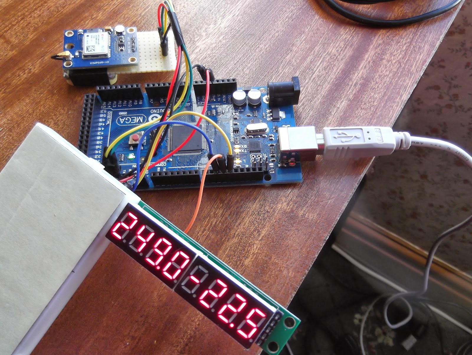
After just an hour or so of research and programming I have the LED displaying the current azimuth and elevation of the FUNCube-1 satellite (AO73) based on the current position and time derived from the GPS!
The first four digits is the azimuth, the second four the elevation.
Arduino, WSPR and AD9850 DDS experiments
Christmas is thankfully behind us so I can get back to what I enjoy doing once I have reorganised my workshop.
As you know I am currently developing a potential High Altitude Balloon (HAB) project and have been experimenting with the Arduino microprocessor platform and have constructed a basic prototype.
With the arrival of the GPS module(s) I have had it successfully working and even took it out for a test walk in the local area, receiving the data and uploading it to the UKHAS habitat system.
NERD-1 and Boris have just been for a walk, first time NERD-1 has had proper GPS and running on batteries. #hab pic.twitter.com/RaKsf1rQhr
— Andrew Garratt M6GTG (@nerdsville) November 23, 2013 This project has revitalised my interest in 'hobby electronics' and I have ideas for a number of other Arduino based projects and have been splashing out on components from eBay. Just before Christmas I purchased an Arduino Mega board, this has more I/O pins than the current Uno and specifically some extra hardware serial ports.
Do any internet search for Arduino based amateur radio projects and it will results in numerous mentions of projects using ultra cheap DDS modules based on the Analog Devices AD9850/AD9851 chipsets.
DDS means Direct digital synthesiser and is a type of frequency generation which can be used for creating arbitrary waveforms from a single, fixed-frequency reference clock. Read the Wikipedia page for more details.
In a nutshell the AD9850 is a chip that under microprocessor control can produce a sinusoidal wave from about 1hz to 40mhz. In other words it is an accurate microprocessor controlled VFO (Variable Frequency Oscillator) or signal generator.
VFOs are the main building blocks of radio receivers and transmitters, so not surprisingly a lot of projects have utilised these modules, rather than the traditional means. Intrigued I ordered a couple of these modules for the pricey sum of £3.50 each!
Using information on George Smart's (M1GEO) website and Simon Kennedy's (G0FCU) blog I quickly had a simple WSPR beacon running!
Experimenting with Arduino and AD9850 DDS and GPS unit.. pic.twitter.com/rxDHQQ1aFd
— Andrew Garratt M6GTG (@nerdsville) December 29, 2013 The Arduino uses the GPS module borrowed from NERD-1 for accurate time and then controls the output of the AD9850 DDS to generate the WSPR signal.Before anyone panics I know at the moment I only hold a Foundation Amateur Licence so the construction of homebrew transmitters isn't allowed. This 'beacon' has no power amplifier and the antenna consisted of an inch or so of wire on the DDS output. I was able to verify the operation using my SDR receiver in the same room.
Construction of commercial kits is allowed under my licence so I have ordered a Ultimate3 QRSS kit from Hans Summers for the pricely sum of £17.50! This uses the same DDS module and same microcontroller as the Arduino.
In the meantime there is also more information and ideas on Eugenr Marcus' (W3PM) webpage about the use of these DDS modules, including making frequency reference sources and calibration using the GPS module.
My new year resolution is to get my Intermediate Licence as soon as possible.. but it has been great to get down to some proper experimenting...
Cannot beat a picture of an oscilloscope to look techy.. my DDS experiments continue... pic.twitter.com/T9OLHOdTLW
— Andrew Garratt M6GTG (@nerdsville) January 1, 2014 Radio shield woes

This rather grainy photo is probably going to be the last one of the Radio Shield. Mainly because of its un-christmas like behavior. the little monster has been misbehaving for a a while. It decides when and if it wants to decode any packets, which is pretty mean if you ask me and to cap it off a new fault has occurred, the LCD screen is very intermittent. The way it works is a bit like this.
1. Plug it in and watch it power up and display the splash screen – all good so far
2. Turn on the rig and tune into 144.800MHz
3. Send it a packet from my VX-8G and watch the LED flash green to say its happy listening and then display the callsign, SSID and associated data
4. turn it off and enjoy some dinner
5. Turn it back on. Get the usual start up message
6. Do nothing else regardless of what I throw at it.
The really annoying thing is that the serial monitor displays other messages that should go onto the LCD bu they stubbornly don’t bother to show themselves. There is definitely a fault somewhere on here so I’ve had to email Argent Data for a bit of a clue. Other little issues are that you can set the contrast or brightness by code (which you should be able to do).
It seems as though you get intermittent packet decoding and intermittent LCD displays, even if you wire up a few others to test. Hmmmm, perhaps I’ll tackle the other parts to the code enhancements later.
Humbug
Frankenrotator
I have published a page on my Frankenrotator project, a cheap homebrew azimuth and elevation rotation system using a Yaesu rotator mated with a Radio Shack TV rotator. The brain of the unit is an Arduino Mega and complete schematics are provided.

The project illustrates how to build a power supply for both DC and AC rotators, replacing commercial rotator controllers. The main control unit powers and controls both rotators and interfaces to a computer using the Arduino native USB port. Logging and control programs command the system via Yaesu GS-232B emulation. The project also demonstrates the use of a remote slave microcontroller. A small waterproof box located at the rotator senses azimuth and elevation. The remote microcontroller is periodically queried by the master unit via a serial link.
I still have to build some antennas to rotate with this system, which I hope to complete before winter sets in here in Pennsylvania. Hopefully I’ll get to chase some satellites in between ice fishing!
Hamradioprojects.com
If you fancy trying your hand at Arduino or Picaxe projects and need to ask a clever person (Don’t look at me,I’ve already put a couple of thicko questions on) then the companion website to the ARRL book is up and running. The code for the projects is on the site too so if you’re not a fan of typing then cut and paste

Argent Data Radio Shield
I’m a bit of an Arduino fan. I’m also interested in APRS. So I was keen to get hold of something that would bring the two together. Enter the Argent Data Radio Shield
I bought one a while ago and used it to make my shack clock. Arduino’s come in a lot of shapes and sizes but the Uno is probably the simplest. You can add bits and bobs to them through stack-able ‘shields’. One of these shields is the Argent Data radio Shield. I ordered mine before going on holiday and got a bit done over on the customs charges but have assembled the little thing and put together one of the simple sketches to show the thing working.

All ready on the bench
All in all the assembly was pretty straightforward with a few parts to put together and not a lot else. You don’t get much in the way of guidance but the suppliers website has all the pertinent information and it shouldn’t challenge most who are ok with a soldering iron. As shown here as a finished article

Ta Daaaaa
Below is a little video clip of the thing running a simple sketch from the website. Instead of the output being to an LCD I’ve sent it to the Arduino IDE serial monitor. This is easily done by not actually putting an LCD on the headers. All nice and simple.


