Archive for the ‘dx’ Category
 News: Olivia Digital Modes on HF
Greetings Olivia and digital mode operators,
GREAT NEWS! WEBSITE UPDATE!
Here are the big three new features:

Live spotting is now available!
- Live Olivia spotting. Just like on POTA and other sites, this is a live show and tell of your activity either by self spotting, or spotting stations you copy. Dedicated live spot page, you can view even on a cell phone.
We are excited to announce a major new feature now live on OliviaDigitalMode.org: an interactive Live Station Spotting tool designed specifically for our digital HF community. Inspired by popular spotting platforms like DXWatch and POTA.app, this system makes it easier than ever to see who is active on the bands, find open Olivia QSOs, and share your own station reports in real time.
Come Join the Live Spotting of Olivia Digital Mode
Whether you are hunting for a contact or tracking band openings across different bandwidths and tone counts, the new spotting tool brings several powerful capabilities straight to your browser:
- Real-Time Live Feed: The spotting page automatically refreshes every 15 seconds, ensuring you always see the latest on-air activity without needing to manually refresh the page.
- Smart Spot Grouping: When multiple operators spot the same station, the system automatically groups those reports together into a single clean line. Instead of duplicate entries cluttering your view, you will see the station, frequency, mode, and a list of all operators who spotted them.
- Timeframe Visual Highlighting: You can easily filter for fresh activity. By selecting a window of 5 minutes, 15 minutes, 30 minutes, or 1 hour, brand-new spots are visually highlighted so you can jump on active signals immediately.
- Flexible Display Options: On the dedicated spotting page, you can choose how many spots to display at once (from 10 up to 250 rows) and toggle between a grouped callsign layout or a detailed chronological log.
- At-a-Glance Homepage Widget: A lightweight summary widget on the main homepage shows the top 5 to 10 most recent spots the moment you arrive on the site.
- Fast Performance and Historical Archives: Active spots stay on the main board for 12 hours to keep queries ultra-fast. After 12 hours, spots automatically move to a historical archive where they remain available for band activity research and propagation analysis.
To keep the spotting board reliable and free of spam, posting new spots will require a simple, free operator account. When you register, you will just need to include a short note for the site administrators to verify your callsign and approve your posting access. Once approved, you can log in anytime and share spots whenever you are on the air.
- Live Calendar of Olivia Events. I have now put live the active calendar functionality on the site, and seeded it with possible calendar events. I will start planning our upcoming events – which require YOUR input on such things as, monthly sprints, special events that you want to do, and, our quarterly QSO parties.
- Feedback form. This is a community website. Now, you can leave feedback; what would you like on the website. What should be different? What is not working? What is working? Please leave us feedback.
Come be a part of this conversational digital mode!
Echoes of CW: A Signal Corps Tribute to Virginia L. Scott and the WAVES of WWII
Looking at this historic photograph brings back a flood of memories from my own time in the Signal Corps. It shows WAVE operator Virginia L. Scott in March 1943, sitting in the Code Room of the U.S. Navy Radio School in Madison, Wisconsin.
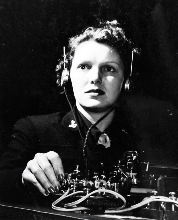
WAVE operator Virginia L. Scott in March 1943, sitting in the Code Room of the U.S. Navy Radio School in Madison, Wisconsin.
The photograph, catalogued in the National Archives as 80-G-431533, captures an ordinary phase of the highly technical work carried out by the WAVES during the Second World War. Seeing her at that workstation with her telegraph key, headphones, and operating table under the glare of direct lighting, I can almost hear the familiar rhythm of CW ringing in my own ears. It is a language of its own, and as an amateur radio operator who loves sending and receiving Morse code, I know exactly the kind of deep focus she is holding in that frame.
During World War II, the Women Accepted for Volunteer Emergency Service stepped up to fill critical roles so that men could be sent to combat zones. Virginia Scott was part of that groundbreaking wave of female personnel who took on demanding technical jobs in the Navy. As someone who has served in military communications, I have immense respect for the structured training and standardized procedures these women had to master.
Radiotelegraphy was the primary transmission tool of the era, the absolute lifeline of naval operations across vast and unforgiving oceans. Long before digital uplinks, it was the sheer skill of the operator that pushed the message through the static.
Her hand rests on that bug key in a way any seasoned Morse code operator would recognize immediately. Sending messages via CW is an art form that requires strict physical and mental discipline. You have to maintain a fluid, consistent rhythm so the operator on the other end, perhaps dealing with heavy interference on a ship thousands of miles away, can copy the signal without error. Scott is entirely focused on executing her message while maintaining the standard posture required by her training. It reminds me so much of the pride we took in the Signal Corps, ensuring every dit and dah was sent with perfect clarity. Dealing with secure information meant there was absolutely no room for sloppy sending.
This specific photograph was originally taken by the U.S. Navy for internal use, but it captured something so profound that painter John Philip Falter used it as a direct reference for a Navy recruitment poster. His painting faithfully reproduced the layout of the scene, turning a moment of routine operational work into a powerful piece of public communication. For anyone involved in the history of communications, and certainly for a fellow CW enthusiast like me, this photo represents a concrete example of how vital these women were. They kept the frequencies alive and proved that the steady hand of a skilled operator was an essential weapon in winning the war.
Here is one of the paintings based on this photograph, and served as a recruitment poster for the WAVES program.

This “It’s a Woman’s War Too! Join the WAVES” poster by John Falter was produced around 1942 as a World War II recruitment tool for the United States Naval Reserve.
This “It’s a Woman’s War Too! Join the WAVES” poster by John Falter was produced around 1942 as a World War II recruitment tool for the United States Naval Reserve. The WAVES (Women Accepted for Volunteer Emergency Service) was established in July 1942, allowing women to serve in the Navy in non-combat roles, such as radio operators and clerical staff. Artist John Philip Falter was a well-known American painter who created numerous propaganda posters and Saturday Evening Post covers, often featuring realistic portraits.
Coast Guard Cutter Chelan: Biggest, Costliest Coast Guard Vessel of its Era
Take a step back in time to November 26, 1928, and take a look at what was then described as the biggest and costliest Coast Guard vessel of its era. The photograph shows the state of the art radio room aboard the U.S. Coast Guard Cutter Chelan. At the time this photo was taken, she was the newest cutter in the service, proudly anchored at the Navy Yard in Washington D.C.

Coast Guard Cutter Chelan
Constructed at a staggering cost of approximately $1,000,000 (1928 Dollars), the Chelan proved her incredible value right out of the gate. On her maiden trip, she picked up a desperate SOS signal and successfully towed a disabled schooner 1,500 miles to safety. This remarkable feat stood as a record tow for the service.
Chelan was laid down by Bethlehem Shipbuilding Corporation at Quincy, Massachusetts, on 14 November 1927 and launched on 19 May 1928. She was commissioned into U.S. Coast Guard service as USCGC Chelan on 5 November 1928.

Turbo-electric cutter, Lake-class (250-footers), built by Bethlehem Shipbuilding Corporation, Quincy, MA, at cost of $900,000 (hull & machinery), launched 19 May 1928, commissioned 5 September 1928, 2,075 tons displacement, 250ft long x 42ft beam x 12ft 11in draft, 17.5kts, armed with 1-5in/1-3in/2-6pdr (1929), 97 crew (1940).
The USCGC Chelan (WPG-45) was a 250-foot Lake-class cutter belonging to the United States Coast Guard, launched in 1928. Best known for its extensive operations in Alaska and a dramatic 1937 North Atlantic rescue, the ship was transferred to Great Britain during World War II.
Sitting at the operator station is Ensign Leslie B. Tollaksen. Tollaksen would go on to have a highly decorated military career, eventually serving as a Lieutenant Commander in World War II where he commanded a naval frigate, the USS Moberly, that helped sink a German submarine in the final days of the Atlantic naval war.
We see Tollacksen in the photo above as a fresh ensign aboard USCGC Chelan. From a genealogy page:
Tollaksen “attended the University of Washington for two years before going and graduating from the US Coast Guard Academy in New London, Connecticut. He graduated from The USCG Academy in the Class of 1927, a year early to man the ships chasing down rum runners.
As a young Lieutenant, he was assigned to the US Coast Guard HQ in Washington, DC. He helped establish “Radio Washington” the telegraph station on Telegraph Road in Washington, DC, and also served as Aid to the Secretary of the Treasury, Henry Morgenthau, Jr. (At that time, his sister worked in the typing pool for President Franklin D. Roosevelt’s White House).

Leslie Bliss Tollaksen (1903 – 1973), Also nown as,”Tolley”
Birthdate: April 13, 1903, Port Townsend, Jefferson County, Washington, United States. Death:1973 (69-70), Fort Lauderdale, Broward, Florida, United States
Leslie, about 1937 was the first US Coast Guard Officer selected for Post Graduate School at MIT.
Leslie, during WWII, and in command of the USS Moberly, sank the LAST German U-Boat U-853. U-8533 was a Type IXC/40 U-Boat, and lays on the bottom off Block Island…”
For history and technology buffs, the equipment in this radio room is absolutely fascinating. In 1928, maritime communication was undergoing a major technological revolution. Global maritime operations were beginning to phase out the older, notoriously noisy spark gap transmitters. Instead, the Chelan was outfitted with modern continuous wave vacuum tube technology. This room housed three powerful transmitters and three highly sensitive receiving sets.
If you look closely at the right side of the image, you can see the large glass vacuum tubes safely housed behind protective metal mesh doors. These power tubes allowed operators to transmit signals on specific, sharply tuned frequencies, reaching much further out to sea without causing interference for other ships. The tall black panels are also loaded with large rheostat dials for tuning, as well as precise ammeters and voltmeters to monitor the high voltages running through the system.
Meanwhile, Ensign Tollaksen has his hand positioned near a traditional straight telegraph key to send out Morse code. The receiver units he operated likely utilized regenerative or early superheterodyne circuits, giving operators the incredible sensitivity needed to hear faint SOS calls through heavy atmospheric static. It was exactly this kind of cutting edge machinery that allowed the crew to hear the distress call that led to their record breaking rescue!

USCGC Chelan was a Lake-class cutter belonging to the United States Coast Guard launched on 19 May 1928 and commissioned on 5 September 1928. After 13 years of service to the Coast Guard, she was transferred to the Royal Navy as part of the Lend-Lease Act, and named HMS Lulworth (Y60). During the war Lulworth served in a convoy Escort Group for Western Approaches Command. She returned to the U.S. Coast Guard after World War II.
USCGC Chelan was a Lake-class cutter belonging to the United States Coast Guard launched on 19 May 1928 and commissioned on 5 September 1928. After 13 years of service to the Coast Guard, she was transferred to the Royal Navy as part of the Lend-Lease Act, and named HMS Lulworth (Y60). During the war Lulworth served in a convoy Escort Group for Western Approaches Command. She returned to the U.S. Coast Guard after World War II.
Read more about this vessel: https://en.wikipedia.org/wiki/USCGC_Chelan.
GERMANY: USAGM Shortwave Operations Return to Lampertheim

Following the recent suspension of Voice of America (VOA) shortwave and medium-wave (AM) transmitters, the U.S. Agency for Global Media (USAGM) is orchestrating a gradual return to the airwaves.
Starting next week, USAGM will begin testing shortwave transmissions from the historic Lampertheim site in Hesse, Germany, which formerly served as a primary broadcasting node for Radio Free Europe and Radio Liberty (RFE/RL). This reactivation indicates that USAGM is working to restore its global broadcast capacity after surviving a period of severe operational cuts and the near-abandonment of its legacy transmission centers.

Lampertheim joins a growing list of international USAGM transmitting stations seeing renewed activity, including sites in Marathon (Florida), Greenville (North Carolina), Kuwait, the Philippines, Botswana, and Thailand. The permanent commissioning of these shortwave sites will depend heavily on the results of ongoing signal testing. The Lampertheim reactivation may ultimately serve as a temporary measure while USAGM awaits the completion of a major transmitter installation and upgrade project currently underway at the Kuwait Transmitting Station.

Built in the early 1950s during the height of the Cold War, the Lampertheim site was an RF (radio frequency) powerhouse, ruling the airwaves with eight massive 100 kW shortwave transmitters designed to pierce the Iron Curtain. Following the corporate merger of RFE and RL in 1976, the station broadcasted both services simultaneously. In 1995, under the newly formed Broadcasting Board of Governors (BBG–the predecessor to USAGM–the station became a consolidated hub for American international broadcasting.

The fall of the Soviet Union and the subsequent independence of Eastern European satellite states drastically altered the station’s mission. The target areas for Lampertheim’s massive curtain antennas were no longer geopolitical priorities, and direct shortwave programming was shrunk to almost nothing.

Instead, Lampertheim’s primary mission shifted toward technical, administrative, and logistical support. It became a vital satellite uplink and distribution gateway, beaming TV and radio programming to relay stations across Europe, Asia, and the Middle East. It also functioned as the remote-control nerve center for USAGM’s global network of transmitters, which included the medium-wave transmitter in Cape Greco, Cyprus (installed at the former RMC Middle East Transmitter Center), the strategic relay station in Djibouti, the massive 1,000 kW medium-wave transmitter in Orzu, Tajikistan, and, Technical oversight for nearly a hundred USAGM-affiliated FM transmitters globally.

During the wars in Afghanistan and Iraq, Lampertheim saw a brief resurgence in direct broadcasting as antennas were reconfigured to target the Persian Gulf and Southwest Asia, filling coverage gaps left by the Kuwait transmitters.

Today, radio enthusiasts and DXers can track the ongoing progress of USAGM’s shortwave broadcasts by consulting the HFCC A26 (Summer 2026) seasonal schedules here: HFCC A26 Schedule: https://new.hfcc.org/data/schedbybrc.php?seas=A26&broadc=AGM

Beyond the Sunspots: Understanding 10 Meter Propagation
I have noticed a common theme regarding propagation on the 10 meter band. There is a wide perception that when the band goes quiet and worldwide DX dries up in June or July, the solar cycle must be diving such that the frequencies become useless. Having written the propagation column in CQ Amateur Radio magazine since 2001, I have done much research into this topic.
The reality is that while the 11 year solar cycle certainly dictates overall band health, the dramatic differences we see between seasons on 10 meters are driven by complex changes in the Earth’s atmospheric chemistry and magnetic field.
The F2 Layer and the Winter Anomaly
During the autumn and spring months, 10 meters comes alive for long range global communication. To understand why this changes with the seasons, we have to look at the F2 layer of the ionosphere.

Complex Propagation Modes
The seasonal shift in thermospheric winds and the resulting chemical changes in the F2 layer are the true drivers of what we experience on the radio. This phenomenon is known in physics as the Winter Anomaly.
The Summer Fade: During the summer months, intense solar heating creates upwelling wind patterns in the thermosphere. These winds pull heavier molecular gases, specifically molecular nitrogen (N2) and molecular oxygen (O2), higher into the F2 region. This drastically increases the recombination rate of ions. The extra nitrogen acts like a sponge, rapidly absorbing the free electrons we need to reflect 28 MHz signals. Because the electron loss is so high, the overall electron density drops, and transoceanic skip fades away.
The Winter Peak: The opposite happens during the cooler seasons. As we move away from summer, the thermospheric winds shift and the heavy nitrogen settles back down. The F2 layer becomes dominated by atomic oxygen (O). Without the nitrogen there to absorb the electrons, the recombination rate slows down significantly. This allows a highly dense F2 layer to build up, reaching peak electron densities around November and February. This atomic oxygen rich environment creates the perfect reflective environment for global 10 meter communication.
Summer’s Silver Lining: Sporadic E
When summer arrives and the F2 layer thins out, the band brings its own unique conditions with the prevalence of Sporadic E propagation.
These intense, highly localized clouds of ionization form in the lower E layer of the ionosphere. Sporadic E provides incredibly strong short skip contacts. These openings typically range from a few hundred to a couple of thousand miles, temporarily replacing the global propagation we enjoy during the spring and fall. Most folks scrolling through social media just want a basic understanding of why they are suddenly making loud contacts into neighboring states instead of talking across the ocean, and Sporadic E is the answer.
Global Reach: TEP and Chordal Hop
For North American operators looking to communicate with places like Brazil or Australia, different propagation mechanics come into play.
For communication down into South America, you are dipping into a fascinating phenomenon called Transequatorial Propagation (TEP). TEP is deeply tied to the F2 layer conditions, but it is heavily driven by the structure of the Earth’s magnetic field near the equator.
Around the geomagnetic equator, the magnetic field lines run exactly parallel to the surface of the Earth. This causes the free electrons in the F2 layer to be pushed outward and downward, creating two massive, highly dense bands of ionization located about 15 to 20 degrees north and south of the magnetic equator. We call this the equatorial anomaly, and it is the engine for TEP.
When you transmit from North America down toward Brazil, your 10 meter signal hits that northern dense band. Instead of reflecting back down to the ground or ocean, the signal deflects horizontally across the equator high in the ionosphere. It then hits the southern dense band and reflects down into deep South America. Because the signal stays entirely in the upper atmosphere and avoids a lossy bounce off the Earth’s surface in the middle, the signals can be incredibly strong and clear. TEP is most reliable during the spring and autumn equinoxes, usually peaking in the late afternoon and early evening hours.
Talking to Australia from North America is slightly different because the path does not cross the magnetic equator at the perfect right angle needed for textbook TEP. However, working Australia often relies on a very similar principle called chordal hop propagation. Instead of bouncing between the ionosphere and the ocean all the way across the Pacific, the signal enters the F2 layer and skips along the underside of the ionosphere for thousands of miles. It stays trapped high up where there is very little absorption, eventually dropping down to receivers in Australia with surprising signal strength.
Regional Variances
Radio wave propagation is never a one size fits all experience. Your location on Earth plays a massive role in what you hear on 10 meters.
The Coasts versus the Midwest: If you live on the East Coast of the United States, your signals have a relatively unobstructed single hop path over the highly reflective saltwater of the Atlantic Ocean to reach Europe. The West Coast enjoys a similar geographic advantage when working Japan and the Pacific Rim. In the Midwest and central USA, your signals must often make an extra hop over land. Because land absorbs radio waves much more than saltwater does, central USA operators might find global F2 paths a bit more challenging. However, Midwest operators are perfectly positioned to work both coasts simultaneously when intense summer Sporadic E clouds form over the continent.
Equatorial Advantage: Operators located closer to the equator experience less of the severe Winter Anomaly shift. Because they sit under the equatorial anomaly, they enjoy much more consistent F2 and TEP openings year round compared to mid-latitude stations.
High Latitude Challenges: Operators in high northern or southern latitudes, such as Alaska or northern Europe, must contend with auroral absorption. During periods of high geomagnetic activity, the auroral oval expands and can severely degrade or completely absorb 10 meter signals, shutting down paths that cross the polar regions.
If 10 meters feels like a completely different band right now, do not blame the sunspot numbers. It is simply the natural seasonal shift in atmospheric chemistry and radio wave propagation at work. Enjoy the loud Sporadic E contacts while they last, and get ready for the worldwide skip to return when the seasons change.
Addendum: From the Southern Hemisphere
I was asked how this looks, from the land of Down Under.
Thank you for bringing the Southern Hemisphere perspective into the conversation! You hit the nail on the head regarding the inclination of the Earth’s axis, and it is the perfect starting point to explain why our experiences are mirrored.
Because the Earth is tilted on its axis by 23.5 degrees, the hemispheres take turns leaning toward the Sun as we orbit. Right now, the Northern Hemisphere is tilted toward the Sun, giving us summer. The Southern Hemisphere is tilted away, resulting in your winter. This means the ionospheric effects we experience are exactly reversed on the calendar.
When you mention that the high bands shut down after dark during your current winter, you are experiencing the harsh reality of wintertime solar geometry. During the winter months in the Southern Hemisphere, the Sun is much lower in the sky and the daylight hours are significantly shorter. While the Winter Anomaly we discussed earlier means your daytime F2 layer can actually become quite dense and highly supportive of 10 meter skip during the daylight hours, that ionization is entirely dependent on active sunlight. The moment the Sun sets at 5:30 PM, the source of ionization disappears. Because the winter night is so long, the F2 layer rapidly depletes, shutting the band down until the Sun rises again the next morning.
Conversely, when you head into your summer months of November and December, two major things happen. First, your daylight hours increase dramatically, which keeps the ionosphere charged much later into the evening and extends your operating time. Second, just as the Northern Hemisphere experiences a massive peak in Sporadic E propagation during our summer, the Southern Hemisphere experiences its own Sporadic E season during your summer. This provides those loud, reliable regional contacts. Finally, as you move into mid autumn around March and April, the Earth reaches the equinox. During the equinoxes, the Sun is directly over the equator, providing optimal and balanced F2 layer ionization for both hemispheres. This is why global, long haul propagation is at its absolute peak for everyone at the same time.
Regarding your question about East to West paths: yes, communication between Australia and South America is fundamentally very similar to the path between North America and Europe. Both are mid latitude transoceanic paths that rely on multi hop F2 propagation.
However, the Southern Hemisphere actually has a distinct geographic advantage for these contacts. Radio waves lose a small amount of energy every time they reflect off the Earth’s surface between ionospheric hops. Saltwater is an excellent, highly efficient reflector of radio waves, while landmasses absorb much more of the signal. Because the path between Australia and South America is almost entirely over the highly reflective saltwater of the Pacific Ocean, your multi hop signals suffer far less ground absorption compared to Northern Hemisphere paths that must often cross large expanses of land. This makes those Southern East to West paths incredibly efficient when the F2 layer is cooperating!
A Pileup? What It Is And How To Work One
Welcome to the chaotic, thrilling world of the HF pileup. Whether you are the one calling CQ from a park in Nebraska or the one hunting a rare DX station, success relies on rhythm, frequency management, and a deep understanding of human behavior.
Here is a proper look at how a pileup appears on a modern display, followed by a complete guide on how to survive it.

A “pileup” on shortwave amateur radio frequencies. The main station is at the low frequency, and stays put. The hunters spread out, above, and call on a single frequency somewhere in the calling window of frequencies (I.e., up five to ten).
Over my decades of working Morse code (CW on amateur radio), I have learned a few critical things about how to navigate the chaotic, thrilling world of the HF pileup. When a rare station or a Parks On The Air (POTA) activator goes on the air, dozens or even hundreds of operators might try to make contact at the exact same time. Working a pileup is an art that takes time to master. Whether you are the one calling CQ from a park in Nebraska or the one hunting a rare DX station, success relies on rhythm, frequency management, and a deep understanding of human behavior.
One of the most important strategies is to determine the operating style of the DX station, specifically discerning how that operator scans the pileup for the next station to work. With modern waterfall displays, that process is MUCH easier. As an example, I worked the Temotu DXpedition (H40RH) that had just started a few hours prior to my attempt. I broke through with only five calls into the pileup, and it took me a mere 60 seconds to call and get an answer. Of course, I first listened and watched the waterfall for about five minutes to get a hang of the operating style of H40RH. This was on 10 Meters where 28.026 MHz was the DX frequency. We callers spread out five to 15 kHz UP in frequency from the DX station because we never want to cover up the DX station with our own signals. Even with a long carrier of intentional interference visible on the waterfall, the visual aid of the SDR made the catch possible. Temotu was a new country for my DXCC, so I am incredibly pleased to have made the contact!
When You Are the Hunted (The Activator)
A Guide To Survive The Pileup
When you are the station that everyone wants in their logbook, you are the conductor of the orchestra. If the pileup senses hesitation, chaos ensues. You must dictate the pace, for both CW and SSB operations.
Controlling the Pileup on CW
Establish a Predictable Rhythm: Your CQ, your exchange, and your QRZ should follow a strict pattern. Consistency allows hunters to time their calls perfectly. If you change your cadence, the pileup gets messy.
Run Split for Large Piles: If the pileup merges into a single continuous drone, go split immediately. You might send “UP 1” to tell callers to transmit one kilohertz above your listening frequency. This spreads the callers out. Send your “UP” frequently enough that the self-appointed pileup police do not take over your transmit frequency. I suggest sending “UP” after each successful logged contact (QSO).
Own the Partials: If you only pull “NW7” out of the noise, send “NW7?”. Do not send “QRZ?” immediately. Stick to that partial call until that specific station finishes the exchange. If they fade out, clearly send “QRZ?” to reset the pile.
Adjust Speed to Control Volume: A slight speed increase (bumping up 3 to 5 WPM) will naturally thin the pileup down to the more experienced operators. Dropping your speed will invite the newer operators back in.
Receiver Management: Back off your RF gain and use a wider filter than you might expect (around 400 to 500 Hz). A filter that is too narrow will cause you to miss the operators who are smartly calling slightly off-frequency.
Controlling the Pileup on SSB
Command with Your Voice: Speak clearly and maintain a steady, authoritative tone. Avoid shouting. Just like in CW, a predictable rhythm helps callers know exactly when to key their microphones.
Use Standard Phonetics: Stick strictly to the standard NATO phonetic alphabet (Alpha, Bravo, Charlie). Cute or custom phonetics confuse operators who do not speak English as their first language.
Acknowledge and Isolate: When multiple voices blur together, listen for the last phonetic letter you can understand. If you hear “Sierra,” say “The station ending in Sierra, go ahead.” Ignore everyone else until that station completes the contact.

My POTA / Portable HF station (a low-power, or, QRP, station).
When You Are the Hunter (The Chaser)
When you are trying to break through a massive wall of sound, raw output power is secondary to timing and sharp observation.
Breaking the Pileup on CW
Listen First, Key Second: Before touching the paddle, listen to three or four complete exchanges. If the activator is working split, figure out their pattern. Are they tuning from the bottom up? Top down? Find where they listened last, and place your transmit frequency just above it.
Use XIT (The Golden Rule): Never perfectly zero-beat the DX station if others are calling. To the activator, three zero-beat stations merge into a single tone. Use your Transmitter Incremental Tuning (XIT) to shift your transmit frequency by 30 to 50 Hz. This slight difference in pitch makes your signal pop out of the receiver passband.
Time the Tail-End: Wait for the massive wall of sound to begin fading, and send your call exactly as the main group finishes. A perfectly timed tail-end call lets your suffix ring out in the clear.
Send Once: When the DX sends “QRZ?”, send your callsign exactly once and listen. Sending your call multiple times just causes interference and slows down the entire operation.
Follow Instructions: If the DX sends “NW7?”, and that is not you, keep your hand off the key. Transmitting over the station they are trying to work only prolongs the pileup for everyone.
Breaking the Pileup on SSB
Study the Cadence: Just like with Morse code, listen to the activator to find the rhythm. Wait for the exact moment the activator stops speaking before you key up.
Drop Your Call and Wait: Say your full callsign once using standard phonetics, then unkey and listen. If you are tail-ending, you might just drop the last two letters of your callsign precisely as the noise floor drops.
Adjust Your Pitch: If you have equalization controls on your radio, boost the mid-to-high frequencies on your microphone audio. A slightly punchy and higher-pitched voice will cut through the bass-heavy rumble of a dozen other stations calling at once.
Working a pileup tests your patience and your ear. Whether you are tapping out Morse code or speaking into a microphone, the operator who listens more than they transmit almost always makes the contact first.
Propagation and the Pile-Up
As many of you know, I was the space weather and radio propagation columnist in CQ Amateur Radio Magazine from 2001 through its demise. I strongly advocate for all HF radio operators to understand the basics of radio wave propagation on shortwave frequencies. There are a lot of myths and frankly, horrific theories on how radio waves propagate.
Understanding how the ionosphere refracts radio waves is a crucial tactical advantage. The behavior of a pile-up changes dramatically based on the frequency band you choose and the current mood of our sun.
The Sun Dictates the Rules
The ionosphere is charged by solar radiation. When solar activity is high, higher frequencies become usable for long distances.
Solar Flux Index: The SFI is a great indicator of overall ionization. A higher SFI means better conditions for the higher HF bands. When the SFI climbs, bands like 15, 12, and 10 meters open up globally.
Geomagnetic Storms: Measured by the K-index, these storms can disrupt communications entirely. A high K-index often absorbs signals crossing the polar regions. This can suddenly mute a massive European pile-up for North American operators.
Fading: The ionosphere is always shifting. Signals will constantly rise and fall in strength, which is known as QSB. A smart chaser listens for the rhythm of this fade and throws their callsign into the pile-up exactly when the band peaks for their specific location.
How Bands Shape the Pile-Up
Every amateur radio band has its own personality. The pile-ups you encounter will reflect these differences perfectly.
10, 12, and 15 Meters: These high bands are daytime frequencies that thrive on high solar activity. When 10 meters opens up, signals can be astonishingly loud with very low atmospheric noise. Pile-ups here can ignite suddenly and stretch very wide across the frequency spectrum.
20 Meters: This is the traditional workhorse band for global communication. Pile-ups on 20 meters are massive, sustained, and densely packed. You will often compete with high-power stations and massive beam antennas on this frequency day or night.
40 and 80 Meters: These low bands come alive at night. They are heavily affected by atmospheric noise and static crashes. Breaking a pile-up here requires an exceptionally well-tuned ear and the ability to pull faint CW tones or muffled voices out of a very high noise floor.
The Skip Zone Effect

The propagation of radio waves.
One of the most confusing aspects of a pile-up for a new operator is the skip zone. Radio waves bounce off the ionosphere and return to earth far away, which means they skip right over the geographic areas in between. You might hear the DX station perfectly, but you might not hear the hundreds of other operators calling them because those callers are inside your skip zone. This phenomenon is exactly why you must rely on the DX station’s cadence rather than waiting to hear the pile-up clear.
While raw power is often cited as the key to breaking a pile-up, your antenna system plays a far more decisive role in your overall effectiveness. A directional antenna, like a Yagi or a hexbeam, not only focuses your transmitted energy directly toward the DX station but also actively rejects interfering signals from other directions. However, do not be discouraged if you are running a simple wire antenna. A well-placed dipole or end-fed half-wave can still break monumental pile-ups if you leverage good timing, exploit the skip zone, and listen closely to the DX operator. Ultimately, the best antenna in the world cannot compensate for poor operating habits.
Over to You
Working a pile-up is one of the most rewarding challenges in amateur radio. It tests your patience, refines your ear, and forces you to understand both the science of radio wave propagation and the psychology of your fellow operators. Every massive wall of sound is a puzzle waiting to be solved.
Now, I would love to hear from you. What was your most memorable pile-up experience? Do you have a specific tactic that consistently helps you break through the noise, or perhaps a frustrating moment that taught you a valuable lesson? Drop your stories and questions in the comments below, and let us keep the conversation going.
From my shack to yours, 73 de NW7US.
Brain Health and Parks on the Air
Got my N3ZN Single-Lever Paddle out of storage, along with most of my POTA station. Despite being homeless and living in the hotel for the last few months (see my personal story on my website), I am trying to keep my brain active and that includes Morse code practice. Why? Besides the health benefit, I want to start getting out into the hotel parking lot and set up to work POTA stations.

Eventually, I will get to an official POTA-registered park, too. We became homeless just as I was planning on activating Ohio parks. Now, I am in Nebraska, and as a disabled veteran, can get into some parks without any big fees.
What is left before I can activate a POTA location? I need to find the antenna and coax assembly that I put together for the whole station. In the meantime, I am practicing to get the cobwebs out of my brain and re-learn that muscle memory. Will also do a lot of receiving practice. Gotta get my brain in gear! Read more about POTA, here. For live POTA on-air spotting, go here.

The Spark in the Wire: How Re-Learning Morse Code Rewires the Brain
There is a unique rhythm to Continuous Wave (CW) amateur radio. As I sit at the key, shaking off the cobwebs and practicing to regain that deep muscle memory, I can feel my brain kicking into a higher gear. It isn’t just about nostalgia or the thrill of making a contact through the static using nothing but tones. There is real, hard science behind why copying and sending Morse code feels like a cognitive tune-up.
In preparing to share this journey, I dove into the research surrounding how learning and practicing CW impacts our neurology. What I discovered confirms what many of us experienced operators have long suspected: Morse code is a powerhouse for brain health and cognitive longevity.
The Cognitive Science of CW
When we sit down for a session of receiving practice, we aren’t just listening to dots and dashes. We are engaging in a complex, multi-sensory cognitive exercise. Research shows that mastering Morse code alters the brain’s structure and functional connectivity in profound ways.
* Neuroplasticity in Action: Studies in neuroimaging have revealed that learning Morse code increases the microstructural integrity of the white matter tracts connecting the auditory and motor cortices. By translating sound directly into physical movement (sending) and physical movement or mental text into meaning (receiving), we are literally forging new neural pathways.
* Bi-Hemispheric Engagement: Unlike ordinary speech, which is heavily localized in the left hemisphere of the brain, processing Morse code recruits areas across both the left and right hemispheres. The left side handles the structural, analytical translation of the code, while the right side processes the rhythmic, musical elements of the pitch and timing.
* Enhancing Working Memory: Receiving CW at higher speeds requires a robust “audio buffer” in your working memory. You must hold the sounds of the characters in your mind, decode them, and write them down or copy them in your head, all while the next characters are already pouring into your ears. This builds tremendous cognitive reserve.
The Koch Method: Training the Brain the Right Way
When I first learned Morse code, and now as I work to bring that muscle memory back, the method of training matters immensely. Trying to count dots and dashes visually or memorizing a chart is a trap. It creates a cognitive bottleneck that falls apart at higher speeds.
That is where the Koch method comes in, a technique that aligns perfectly with how our brains naturally process fast, rhythmic information.
* Full Speed from Day One: Invented by German psychologist Ludwig Koch, this method dictates that you listen to characters at your target speed right from the start, typically 20 words per minute or faster.
* Preventing the “Counting” Habit: By keeping the character speed high, your brain is physically incapable of counting the individual dots and dashes. Instead, you are forced to learn the overall rhythmic “sound basket” or shape of the letter.
* Incremental Success: You start with just two characters. Once you can copy them with 90% accuracy, you add a third, then a fourth. This builds immediate, reflexive muscle memory rather than analytical translation.
CWops, CW Academy, and LICW: Modern Gold Standarda
In my exploration of modern training tools that honor this science, I found that the amateur radio community has perfected this instructional approach. Organizations like CWops, through their renowned CW Academy, have taken the core principles of the Koch method and elevated them for the modern era. Another adaptation from the Koch method is the Long Island CW group (LICW) website and support structure.
* Rhythm and Spacing: CW Academy utilizes effective spacing methods related to the Koch philosophy. They send characters at a high effective speed so your brain learns the correct sound patterns immediately, while widening the space between the characters to give your mind time to process them.
* Structured Discipline: Their programs offer the exact kind of structured environment required to overcome writer’s block or training plateaus. It combines the rigorous discipline of daily practice with the support of a community.
* Interactive Learning: By pairing rigorous receiving practice with peer interaction, they stimulate the social and cognitive centers of the brain simultaneously, maximizing the neuroplastic benefits of the hobby.
Final Thoughts: Getting the Gears Turning
Re-learning CW is more than just a return to a beloved pastime. It is a deliberate act of cognitive preservation. Every evening spent copy-practicing and burning those pathways back into my hands is an investment in focus, memory, and mental sharpness. The science proves it, but sitting at the desk, feeling the cobwebs clear as the code starts to flow naturally once again, is all the proof I truly need.
Here’s just some practice after adjusting the key gap spacing and tension.


