Archive for the ‘antenna’ Category
 Comparing two antennas with WSPR
WSPR – The system for Weak Signal Propagation Reporter makes it easy to compare antennas if your transmitter can easily switch antennas. The system shown here can send on antenna 1 for almost two minutes and then switch immediately to antenna 2 for the next transmission.
The Ultimate 3S already has software that supports that and application note 3 from QRPLabs (Controlling additional relays using the Ultimate3S “Aux”) describes how. I built mine following that note and the experience from EA1CDV.
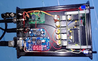
The circuit is controlled from pin D7 and consists of a transistor, a relay, a resistor and an electrolytic capacitor. In addition I have two LEDs that indicate which antenna which is in use. In the first picture the green LED in the back right under the BNC antenna connector shows that antenna 1 is connected.
In the next picture, the whole layout is shown a little better. In this case LED 2 is lit, the faint yellow one. It sits right under the additional SMA antenna connector in the top left-hand corner that I had to fit.
I have used this setup for a few days now on 7, 10, 14, and 18 MHz with some crossed doublet antennas (somewhat like this setup, but not in the same location). I change the frequency between antennas, e.g. 50 Hz below the center frequency of the band for antenna 1 and 50 Hz above for antenna 2 in order to simplify discrimination between the transmissions.
The short 13 m antenna transmits best East-West, and the longer 26 m antenna North-South. The directivity is in general confirmed by the WSPR reports I see. Sometimes the difference can be more than 10 dB in SNR, but more often it is closer to 5 dB. But it also happens that only one of the transmissions is detected. This should make for some interesting analysis in the coming months.
The post “Comparing two antennas with WSPR” first appeared on the LA3ZA Radio & Electronics Blog.
 Comparing two antennas with WSPR
WSPR – The system for Weak Signal Propagation Reporter makes it easy to compare antennas if your transmitter can instantly switch antennas. The system shown here can send on antenna 1 for almost two minutes and then switch immediately to antenna 2 for the next transmission.
The Ultimate 3S already has software that supports that and application note 3 from QRPLabs (Controlling additional relays using the Ultimate3S “Aux”) describes how. I built mine following that note and the experience from EA1CDV.
The circuit is controlled from pin D7 and consists of a transistor, a relay, a resistor and an electrolytic capacitor. In addition I have two LEDs that indicate which antenna which is in use. In the first picture the green LED in the back right under the BNC antenna connector shows that antenna 1 is connected.
In the next picture, the whole layout is shown a little better. In this case LED 2 is lit, the faint yellow one. It sits right under the additional SMA antenna connector in the top left-hand corner that I had to fit.
I have used this setup for a few days now on 7, 10, 14, and 18 MHz with some crossed doublet antennas (somewhat like this setup, but not in the same location). I change the frequency between antennas, e.g. 50 Hz below the center frequency of the band for antenna 1 and 50 Hz above for antenna 2 in order to simplify discrimination between the transmissions.
The short 13 m antenna transmits best East-West, and the longer 26 m antenna North-South. The directivity is in general confirmed by the WSPR reports I see. Sometimes the difference can be more than 10 dB in SNR, but more often it is closer to 5 dB. But it also happens that only one of the transmissions is detected. This should make for some interesting analysis in the coming months.
The post “Comparing two antennas with WSPR” first appeared on the LA3ZA Radio & Electronics Blog.
 Inverted L
I needed a cheap and relatively unobtrusive solution and I found one in Len Paget's (GM0ONX) design for an inverted L. The full details were printed in the Practical Wireless magazine several years ago and PDFs are available for download from Len's website. The designs make use of coaxial traps, one for the 80m version, two if you want to add a top-band (160m) option.
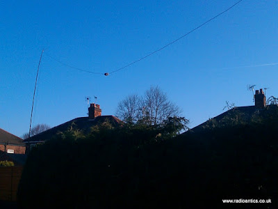
Opting for the smaller 80m version I set about building one. Using an old fibre-glass fishing pole about 5m high at the far end of the garden tucked behind the summer house which I could collapse down and then retract the wire elements when not in use so hiding it from view.
The fun and interesting part was building the trap. They are formed by coiling some coax, in this case RG58, round a former such as plastic waste pipe. I had a bit of scrap pipe but it was 32mm not the 40mm diameter type described in the article, thinking it couldn't make 'that much difference' I built one using the same number of turns but the resultant antenna wasn't anywhere near resonant according to the analyser.
I decided I needed to test the trap's frequency response. I found a YouTube video by Dave Tadlock (KG0ZZ) where he demonstrates using a MFJ 'Grid Dip Meter' adapter on an MFJ antenna analyser to test coaxial traps.
The adapter consists of nothing more than a coil of wire on a suitable former so I made my own to use with my AW07A analyser. It worked a treat and I discovered my trap was way off frequency. In the mean time I had located a useful PDF document by David Reynolds (G3ZPF) which informed me I actually needed 180cm of RG58 round a 32mm pipe to make a suitable 7MHz trap, so I made another.
I made a small video showing the traps and how I tested them.
The resulting antenna seems to perform well, but it does sag a little due to the weight of the trap and wire and the flimsiness of the pole. But I have made a number of contacts on it and used it during the RSGB 80m CC Datamode contest a few weeks back. It was my first go at this contest but once I got the hang of operating it was great fun.
 Just the medicine for lowering impedance
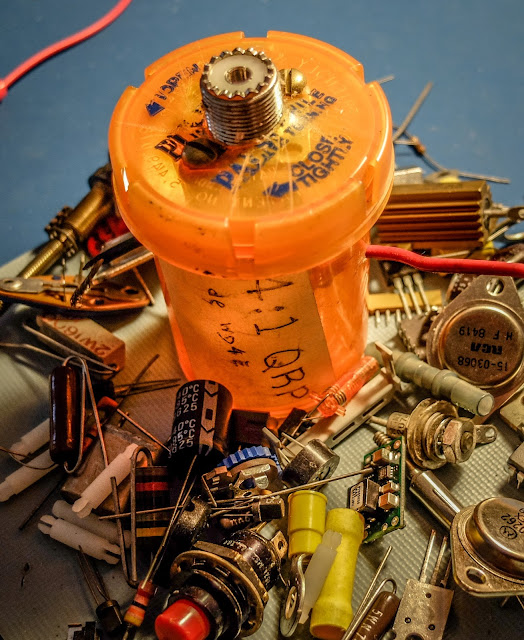
Pill bottle balun
 |
| If I could save RF in a bottle... |
The child and arthritis proof cap keeps the goods away from young and old alike...
Just what the doctor prescribed...
 LHS Episode #164: Ancient Antenna Modeling
 We're done with the editing of Episode #164 and here it is for your listening pleasure. In this episode, your hosts tackle topics from Bugbook computers to permanent amateur radio licenses, from Turing phones to Raspberry Pi computers and from antenna modeling software to lobster on pizza. We hope everyone will find something to enjoy. Please let us know by sending us feedback. We'd love to hear from you.
73 de The LHS Crew
 I will have a BLT please
The BLT-Plus Balanced line QRP tuner
I was looking for a QRP tuner for the 1Watter 40m transceiver I am building that would work with both balanced feedline antennas as well as coax feedline. The traditional Z-Match tuner is quite efficient at tuning balanced line antennas and the built-in SWR bridge gives you an all-in-one tuner and SWR indicator without having to take a separate SWR meter along with its inherent mess of cabling a separate SWR meter. The BLT in the name stands for "Balanced Line Tuner". |
| The Kit as it comes out of the bag |
Why use a z-match ?
- Matches balanced loads without the use of lossy baluns.
- Being a parallel resonant circuit, the Z-match can provide some band-pass filtering for your receiver and harmonic attenuation for your transmitter.
- A well-designed Z-match tuner has a high Q and is more efficient (less lossy) than other types of tuners.
- The fixed inductor simplifies construction (no taps or rollers needed).
The secret sauce
Built in SWR indicator
 |
| SWR bridge with LED indicator |
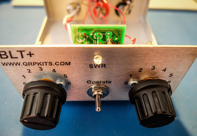 |
| Switch to Tune to present a low SWR to the transmitter while matching, switch to Operate when finished |
Building
- The kit is provided with really nice water slide decals that give it a commercial look (if you don't ruin them like I did). The instructions recommend applying a clear coat to the decals after they are applied. I used a Krylon matte finish clear coat which indicated it was fine for metals and plastics but it partially melted the decals and caused them to bubble. I'd suggest testing whatever you are going to clear coat them with first.
- Don't over tighten the plastic tuner shafts or you won't be able to slide the knobs on (yes I did).
- The binding posts have little plastic spacers that separate and it isn't obvious. If you install them and wonder how they don't ground themselves (like I did) you've done it wrong and will have to go back after it's together and try to remove them with all the wiring in place.
- The bolts for the binding posts are very soft metal and the nuts can strip them if you apply too much force (yep I did that too).
- The main toroid has three sets of windings and they overlap. Pay attention to the instructions about winding them all in the same manner (clockwise or counter clockwise) or you will have to rewind them (yep, I did that too).
- The 3 windings on the main toroid overlap so you won't be able to go back and verify your turns when doing the 2nd and 3rd winding so count carefully (ask me how I know).
- Temporarily attach the SWR bridge to the front panel to get the spacing correct to solder the LED leads.
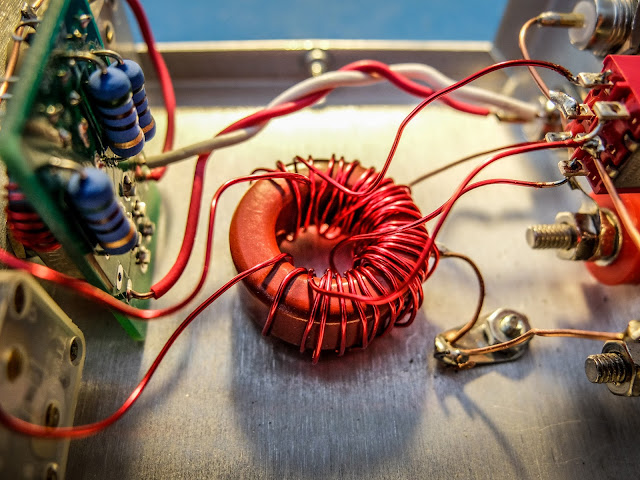 |
| My messy toroid winding... but it's working fine |
Operation
- Connect your transmitter and antenna.
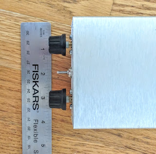
- Choose the appropriate switch in the back for coax or balanced line antenna (Up for coax, Down for balanced line).
- Start with the inductance switch on the back set to low-impedance (Low-Z) because it is the most efficient. It uses the 6 turn secondary rather than the 12.
- Switch the front switch to "Tune"
- Key the transmitter and be sure you are using 5 watts or less
- Turn the "Load" knob first until you see a dimming of the LED then the "Tune" knob to make it go out completely
- The knobs interact so you'll need to go back and forth between them to achieve best match
- If you can't get a good match switch the inductance switch on the back to "High Z" and try again
- Don't apply power too long at a time during tune because the 50 Ohm resistors are heating up in there during the Tune process
- When the LED goes out or gets very dim you have a very good match. Switch to "Operate" and enjoy a well matched antenna
Photos
 |
| Result of having to rewind the secondaries made it messier than I'd like |

