Author Archive
 e-Bay PCB Thermal Transfer Paper
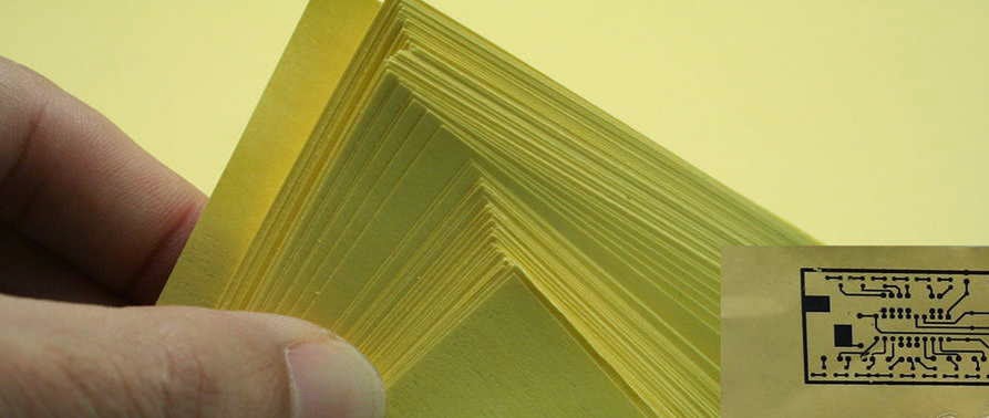 This past weekend I had the first opportunity to try my e-Bay purchased thermal transfer paper. It was to be used in my iron-on PCB work as a hopeful improvement over what I had been using...just ordinary printer paper. Supposedly the shiny photo quality papers were proving to be good performers but are expensive. Some have reported good results with glossy magazine paper but my one experience with that was not a pleasant one. Unknowingly, when I had removed the magazine page, a small amount of the sticky adhesive used in the binding process was still on the sheet. Running it through the printer caused it to melt and smear some of the laser cartridge's toner and for the next several weeks, any printing I did had a slight black streak along one edge...doh!
 My new paper from China (free shipping!) was pretty inexpensive and if it offered even a slight improvement, would be well worthwhile. This first use of the paper would be a circuit board for my earlier test-bed GW3UEP 630m transmitter. I had finished designing a PC pattern for it, using MS Paint, and was anxious to see the results.
 |
| Courtesy: http://www.gw3uep.ukfsn.org/ |
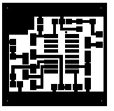
I know that a lot of folks turn up their noses at MS Paint but I have always found it to be a very versatile piece of software and have used it for making PC layouts for many years. I also use it for drawing all of the schematics appearing on my website.
After printing the pattern (printer set for maximum resolution and darkest print) and ironing-on the pattern , I allowed the board to cool for several minutes before immersing it, along with the now firmly attached yellow paper, into cold water. The first thing I noticed was how easily the paper came away from the board. It actually 'un-peeled', much like a good quality price tag sticker...you know.... the ones that don't take forever and come off in tiny bits and pieces. It peeled off smoothly with no paper residue left on the board. This was a huge improvement already. There were just a few traces of toner left on the paper as almost all had been transferred to the board.
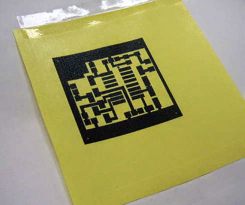 Once dried, a close examination revealed that I had pressed a little too hard with the iron and there was some evidence of 'squeeze-out' along the edges of some lines. I also found one or two very small thinner areas that probably required going over with a permanent-ink black marker pen just to make sure that those spots did not get etched. Over all I was extremely pleased with the paper and will be using it from now on.
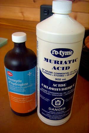
Another recent change in my PC etching regime has been a switch from the old Ferric Chloride standby to a combination of Hydrogen Peroxide and Muriatic acid. Not only does it seem to etch more cleanly (no undercutting) but it also etches very quickly and without any solution warming needed. This board was completely etched in just over 4 minutes.

The chemicals used in this method are inexpensive and are readily available at the drugstore and at the hardware store. There are numerous web-descriptions of this particular etching process but this site seems to cover the basics nicely.
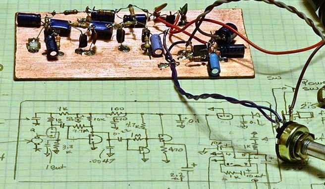
The completed board turned out as shown here:
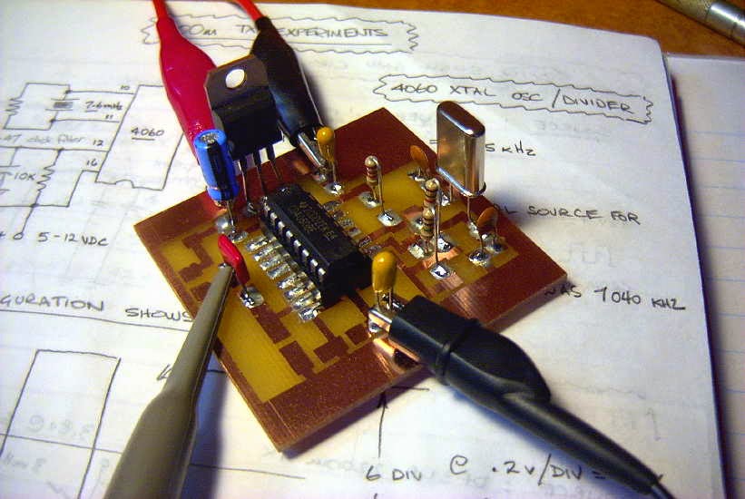
The CD4060 not only functions as a crystal oscillator but also as a versatile frequency divider. As well as fundamental frequency output, ten different 'divide-by' functions are available depending in which output pin is chosen. These range from divide-by 16,384 to divide-by 16. This circuit uses the latter, dividing the 7.6 MHz crystal down to 475 kHz at pin 7.

In summary, I can highly recommend the e-Bay yellow thermal transfer paper when used for this method of making PCB's and is much cheaper than buying photo-quality printing paper.
On Making Nanowaves – Part 3
Having studied many of the receiving systems being used by others, it seemed that designs ran from the 'very simple' to the 'very sophisticated'. Once again I looked to Roger's experimental work involving receivers since the one he had been using had evolved over a period of several months and several tweaks. The design that he used was an adaptation of the original low-noise PIN diode laser receiver designed several years ago by K3PGP and shown here on K3PGP's Experimenter's Corner.
Roger's adaptation, shown below, appeared to be getting excellent results when used in his over-the-horizon clear air scattering tests.
Although Markus, John and myself all built the same design, it is interesting to see the end results, as each used a different construction method.
John chose to use perfboard and point to point-to-point wiring:
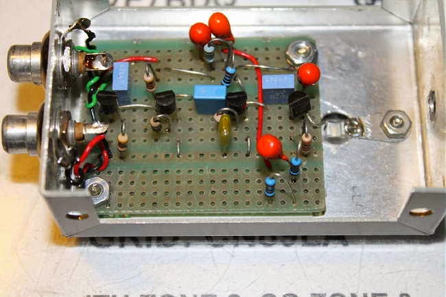 |
| VE7BDQ's Perfboard RX |
 |
| VE7SL's PCB RX |
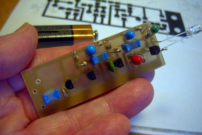
 |
| VE7CA's Dead-Bug Style RX |
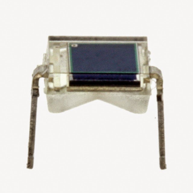 All of us used the Osram BPW34 PIN diode for the detector after having it recommended by Clint in e-mail 'detector discussions' as being a good performer . It is still readily available from the usual places, at around eighty-cents.
 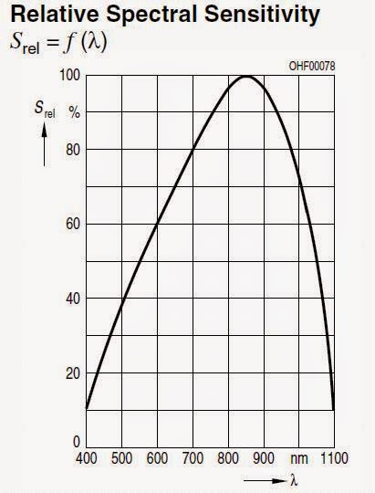 |
| BPW34 Spectral Range |
Many silicon PIN photodiode detectors are available with filters that let them achieve maximum sensitivity at the lower IR range while blocking the unwanted higher frequency visible light sources. Such is the case with this one, available as the BPW34FA. If you wanted to run an all IR system, reducing visible light QRM, this detector might be a better bet.
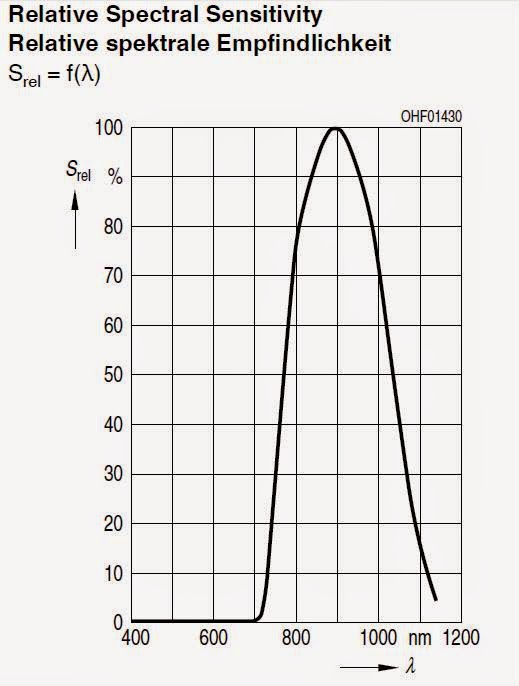 |
| BPW34FA Spectral Range |
When it comes to diode detectors, there are always new challengers appearing in the marketplace. There are still many opportunities for experimenting when it comes to optimizing the front-end of your receiver.
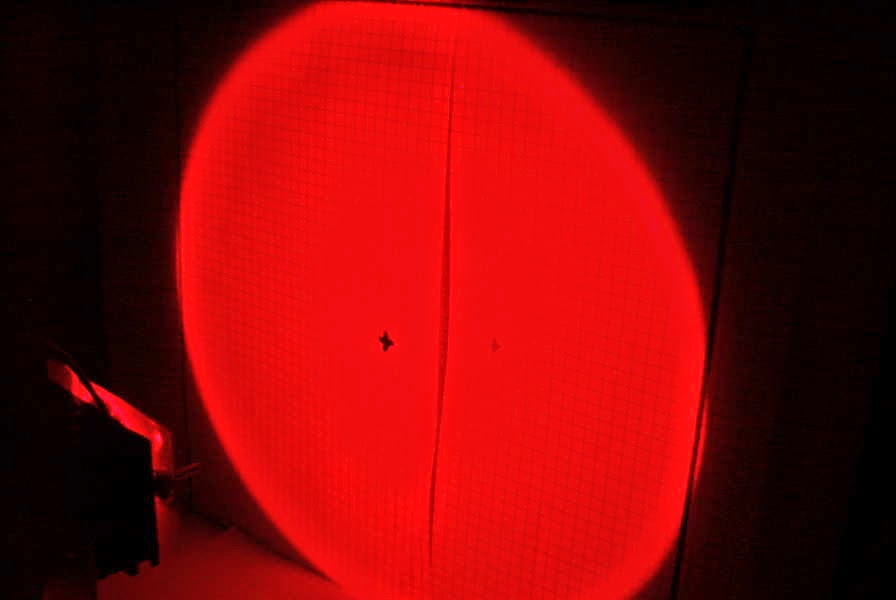
When coupled with its focusing lens in the final stage of construction, the receivers are amazingly sensitive. Even the slightest hint of a light source, often invisible by eye, would produce a response from the system....even starlight!
One of the first sounds detected was a low-pitched and repetitive 'thump-thump' which turned out to be the wingtip strobe lighting of jet aircraft activity approaching and departing Vancouver International Airport. After several nights of listening it was apparent that the strobe lighting could be detected from at least 70 miles out and from aircraft still above 10,000'. Panning over to the runway (about 25 miles away), I could often detect the strobes from departing aircraft even though they had not appeared above my sea-level horizon. Eventually I would see them rise above the horizon, about a minute after hearing them on the runway while on their takeoff roll. I suspect the propagation mode would be a form of clear-air scatter since there was no direct line-of-sight to the signal source when initially heard.
Panning the receiver slowly along the many miles of coastal mainland, on the other side of Georgia Strait, revealed many signals, most of them with different audio signatures. Some sounded rough and buzzy, like an unfiltered CW note, while others were T9 and very clean. Most had different repetition rates resembling radar sweep speeds but, once again, most sources were not visible to my eye...nor were they located when scanning the signal source with binoculars. I suspect that most signals were from various fixed lighting installations either strobe lighting or area flood lighting. Some targets appeared to be slowly moving and were found to be coming from tankers and container ships travelling along the far coast line. Hearing so many of these modulated lightwave signals was certainly an interesting experience and something I had not really expected. Even individual stars would produce a detectable 'hum' as the receiver/lens combination was aimed directly at them.
My one and only daylight test revealed extremely high levels of hum from the bright sky and, no doubt, front end overload desensitising....but the sudden sound of a buzzing bee in the headphones turned out to be just that, as the reflected light from its wings was being modulated by the rapid flap-rate....all very eye-opening to me and totally unexpected.
Here are some recent audio recordings made during a period of heavy cloud cover over Georgia Strait. All are on the far mainland coast or further inland and most sources were not visible to my eye.
- Landing aircraft strobes at Vancouver International ~ 30 miles.
- Aircraft over Georgia Strait, ~ 40 miles.
- Unidentified with odd repetition rate.
- Washington coast unidentified ~ 30+ miles.
- Washington coast unidentified 2.
- Washington coast unidentified 3.
I think such a system would make a wonderful 'science-fair' project for a budding student, complete with recordings....but perhaps it has all been done before!
For a very in-depth study of various current RX designs, see the Optical Receivers page of KA7OEI.
With all three receivers working well, the transmitters would be next....
On Making Nanowaves – Part 2
Now it seemed that up until just a few years ago, most amateur lightwave work had been done using lasers. The UK boys, as well as others, were now using LEDs, whose technology had made huge strides in recent years. The 'non- coherence' of LED light, unlike lasers, offered a distinct advantage when used for communications. Fading and signal dropout during periods of poor visibility were significantly reduced with the non-coherent LEDs when compared with laser light's 'all or nothing' characteristics.
Courtesy: KA7OEI As well, the thought of using lasers was somewhat scary in view of the growing amount of negative publicity from frequent reports of irresponsible use....combined with the fact that my path to VE7CA had to cross Vancouver International Airport!
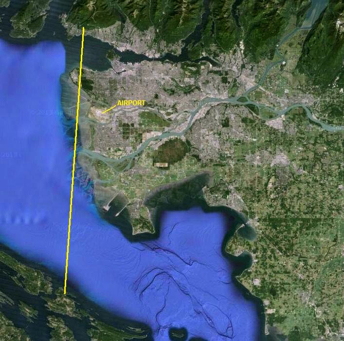
Shining just a low-powered laser across this region was not something that I felt even remotely comfortable about doing. I felt much better about the project the more I learnt about LED's and of the good results being had by other experimenters.
Another exceptionally good source of valuable information (and probably the best on the Internet) is the 'optical' page site of Clint Turner, KA7OEI. Clint is an exceptionally gifted engineer-experimenter and is extremely generous in sharing his knowledge with others. As our local project developed over the course of many weeks, we exchanged several e-mails. My numerous questions would always result in very long detailed answers...and precise explanations for the reasons behind the answer or suggestions.
Just name any radio-related activity and Clint seems to be not only involved in it but has excelled in it. His willingness to share with others is just another example of why our hobby is so enjoyable!
While still deciding on receiver / transmitter designs, I built a small audio tone generator that would be needed, no matter what type of transmitter was eventually built. The plan was to have some method of making our signals stand out when searching for them in the noise. A distinctive two-tone FSK alert tone was decided upon as it could easily be built using a pair of 555's or a single 556. The final module allowed for three separate modes...an FSK 'beacon' mode, a keyed 'CW' mode and a short 'dash' mode (less annoying than the 'alert' tones).
Here is a recording of the FSK 'beacon' mode in action.
The base tone was set at about 600Hz since we preferred the lower tone for CW work.
No doubt there are other methods of building the FSK alert module but the 556 is simple and worked well.
For very weak-signal CW work, likely involving slow-speed (QRSS) modes in future 'non-line-of-sight' (NLOS) 'cloudbounce' trials, something with a bit more accuracy such as a crystal oscillator divided-down to audio frequencies would be better. Such a system would be very stable and provide a more precise modulation frequency... necessary for the narrow bandwidth viewing windows required for Argo or similar DSP audio viewers.
With the tone generator taken care of, the receiver was next on the list.
Shining just a low-powered laser across this region was not something that I felt even remotely comfortable about doing. I felt much better about the project the more I learnt about LED's and of the good results being had by other experimenters.
Another exceptionally good source of valuable information (and probably the best on the Internet) is the 'optical' page site of Clint Turner, KA7OEI. Clint is an exceptionally gifted engineer-experimenter and is extremely generous in sharing his knowledge with others. As our local project developed over the course of many weeks, we exchanged several e-mails. My numerous questions would always result in very long detailed answers...and precise explanations for the reasons behind the answer or suggestions.
 |
| Clint Turner, KA7OEI |
Just name any radio-related activity and Clint seems to be not only involved in it but has excelled in it. His willingness to share with others is just another example of why our hobby is so enjoyable!
While still deciding on receiver / transmitter designs, I built a small audio tone generator that would be needed, no matter what type of transmitter was eventually built. The plan was to have some method of making our signals stand out when searching for them in the noise. A distinctive two-tone FSK alert tone was decided upon as it could easily be built using a pair of 555's or a single 556. The final module allowed for three separate modes...an FSK 'beacon' mode, a keyed 'CW' mode and a short 'dash' mode (less annoying than the 'alert' tones).
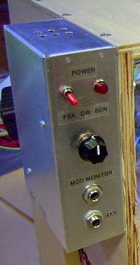 |
| Modulator mounted on TX |
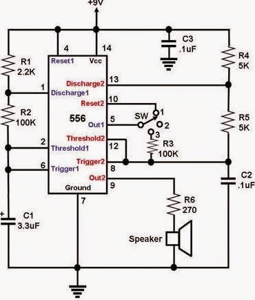 |
| Courtesy: http://electronic-projects.50webs.com/p1.htm |
No doubt there are other methods of building the FSK alert module but the 556 is simple and worked well.
For very weak-signal CW work, likely involving slow-speed (QRSS) modes in future 'non-line-of-sight' (NLOS) 'cloudbounce' trials, something with a bit more accuracy such as a crystal oscillator divided-down to audio frequencies would be better. Such a system would be very stable and provide a more precise modulation frequency... necessary for the narrow bandwidth viewing windows required for Argo or similar DSP audio viewers.
With the tone generator taken care of, the receiver was next on the list.
On Making Nanowaves – Part I
 During last year's fall season, VE7CA (Markus), VE7BDQ (John) and myself were getting prepared to venture into the nanowave world....that part of the electromagnetic spectrum that lightwaves of various wavelengths call home.
Over the course of many months, I had become intrigued by the lightwave experimentation being done by amateurs in the UK and particularly those being done by Roger, G3XBM. Like many of the UK builders, Roger had been building and testing simple low-power LED lightwave transmitters along with simple receiving systems. It was fascinating to follow his progress thanks to his daily blog (read his '481tHz' optical postings here) which documented every detail...both failures and successes. Even though not amateur radio per-se, to me it represented the best of what is so wonderful about our hobby and experimental homebrewing in particular. Unknowingly, Roger had me hooked and eventually I started to seriously contemplate building a lightwave system.
What finally pushed me over the building-brink was an amazing series of articles by Stuart Wisher (G8CYW) published in Radcom magazine and now available for download on Yahoo's "UK Nanowave Group". This four-part series was full of ideas, schematics and inspiration. I would challenge any homebrewer to read them without wanting to start building almost immediately! The group itself is an excellent source of circuits and up-to-date information regarding the latest activity amongst the UK amateur 'nanowavers'.
Now.... just having a lightwave system would not be much fun without having someone else to talk to. My first challenge was to find someone, preferably another ham, with whom I might be able to communicate once I had a system built and....they would need to be a homebrewer as well since none of this stuff was available 'off the shelf '. I contacted Markus (VE7CA), a very skilled homebrewer and sent him the series of Radcom lightwave articles. I did the same with John (VE7BDQ), another ardent builder and the main motivator (although he never knew it at the time) in me becoming hooked on ham radio as an early teenager. Both immediately called 'all-in'....our nanowave project was off and running!
Special 630m Activity Night This Fall
"Special Event Planned this Fall on 630 Meters
Experimental operators on 600/630 meters will conduct a special event operation October 31-November 2. The Maritime Radio Historical Society (MRHS), which maintains the KPH/KSM commercial coast stations, will take part in the event.
“This event marks the 106th anniversary of the Berlin Treaty that created the international distress frequency at 500 kHz,” said ARRL 600 Meter Experimental Group Coordinator Fritz Raab, W1FR. “This will be a CW event.”
Raab said some stations will operate beacons on the experimental band, transmitting anniversary messages, while others will simulate the sort of maritime communication that once occurred in this part of the medium-wave spectrum. They will call CQ on a designated calling frequency and then change frequency to complete the contact. Silent periods will be observed.
The activity will occur between 465 and 480 kHz and between 495 and 510 kHz. “Different licensees have different frequency authorizations,” Raab noted. “The designated calling frequencies are 475 kHz for the lower band, and 500 kHz for the upper band.”
Raab noted that this may be the last such event that includes operations on 500 kHz itself. “This band is not being included on new experimental licenses, as it is supposedly reserved for a new maritime-data service,” he explained. He said he anticipates that more information will be released as the event draws closer. "
Not seeing any mention for Canadian activities in the event, I contacted the organizer and ARRL 600m Experimental Group Coordinator, Fritz Raab (W1FR). I asked Fritz if it would be possible for the three active Canadian 630m stations (VE7BDQ, VO1NA and myself) to 'officially' become part of the planned activities. I suggested to Fritz that the three of us could offer the chance for amateurs in both Canada and the U.S. to actively communicate with some of the 630m Canadian stations by working in the 'crossband' mode. Each of the three stations would have their own assigned transmit frequency and, following CQ's, would listen on specified HF frequencies for any answering stations. Fritz was delighted to add us to the program and the next '630 m Activity Night' announcement will include all of the details including exact frequencies.
 | |||
| Joe - VO1NA |
VO1NA will be transmitting from Torbay, Newfoundland and should be very well heard throughout eastern North America. Joe will be listening for replies on both 80 and 40m CW.
 |
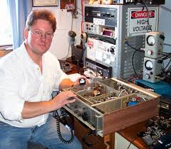
| John - VE7BDQ working 2200m - 160m crossband at VA7LF |
VE7BDQ will be transmitting from Delta, B.C., south of Vancouver. John will be listening for callers on 80m CW only. Being a retired Canadian Coast Guard RO, John has many years of experience manning the 500kHz watch when 600m maritime activity was in its prime.
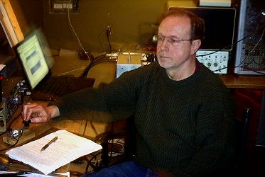
VE7SL will be transmitting from Mayne Island B.C., midway between Vancouver and Victoria, on Vancouver Island. Like Joe, I plan to listen for callers on both 80 and 40m CW.
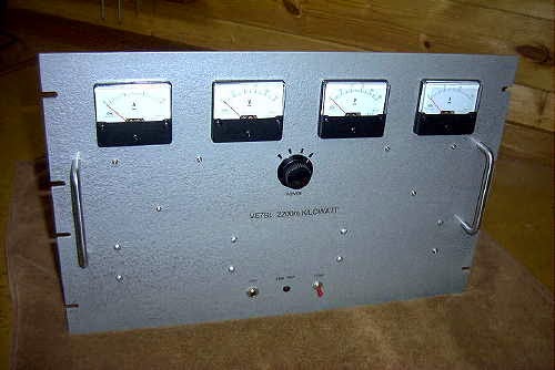 |
| VE7SL - 2200m / 630m TX |
All three Canadian stations are able to muster the maximum allowed eirp for 630m and with the improved propagation of late October, the opportunity for some interesting crossband contacts should be realized on both ends of the continent.
There will be more details well before the event but hopefully you can become part of the fun by giving some of the crossbanders a call on their HF 'QSX' frequencies....and if you know of anyone that might like to participate, please let them know about the upcoming event as, like so many on-the-air activities, the more the merrier!
The Magic Grows Weaker

Recent comments on the ON4KST 6m chat page tend to indicate that the summer's Sporadic-E season is rapidly drawing to a close...."time to move to 160?" ..."how long 'til Es season? " ..... "is that it for the year?". Peaking around early July, I'm always surprised at how rapidly the three-month propagation-party zips by and, as always, leaves us wanting just a little bit more.
Unlike the past several summers, I had no European QSO's this year. The July 27th VE6 - Europe event was as close as it came but who knows what might have been missed during some of those predawn propagation periods when most west coasters are still sawing wood. Ever-vigilant KL7KY was alert enough to find Europeans at 0300 his time, on two separate July occasions, making me wonder if the same thing might happen down here as well? After Kevin's over-the-pole success, I started all day and overnight scans of the northern Canadian beacon segment (50.010 - 50. 050) with the 756PROIII's versatile (non-squelched) scan mode and the yagi pointed at 035 degrees. Even considering my somewhat late-season start, I was surprised at how often the beacons were making an appearance, often popping-up late in the evening or in the middle of the night....without the scan, these conditions would normally go unnoticed. I probably began my scans too late in the season and next summer will begin earlier, about mid-June through mid-July, hopefully giving me a better chance for Europe. John, VE7DAY, has also expressed interest in pursuing this more diligently next summer as well and has even spoken of daily 0300 over-the-pole CQ's during the mid-season's peak period.
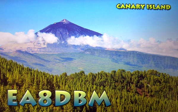 The season highlights for this summer are very few....contacts with LU5FF, BV2DQ, EA8DBM, several dozen JA's and one new U.S. grid for the FFMA struggle.
I still need 49 grids to have all 488 continental U.S. grids confirmed but at this year's rate I'll need to live until I'm 115.
Six meters may yet still hold a late-season surprise for us but if the fat-lady hasn't already sung then she's just behind the curtain ....clearing her throat.
Your LF Station’s Best Friend – The Scopematch PT.II
 As mentioned in Part I, my construction of the MØBMU-designed Scopematch has proven to be the most valuable piece
of test gear in my LF station. If you plan to become active on our new 630m
band, it is well worth taking a few hours to build as it will make antenna
tuning much, much easier than trying to get your antenna tweaked using other
methods.
As mentioned in Part I, my construction of the MØBMU-designed Scopematch has proven to be the most valuable piece
of test gear in my LF station. If you plan to become active on our new 630m
band, it is well worth taking a few hours to build as it will make antenna
tuning much, much easier than trying to get your antenna tweaked using other
methods.After building and installing the new Scopematch, a quick check of what I thought had been a properly-tuned system, surprisingly revealed that my 2200m antenna was neither matched correctly nor tuned to resonance! In spite of my poor-tuning (using the system shown in my last post), I had still received a number of encouraging reception reports from VE6, Washington and Oregon, giving me false and undeserved confidence in my earlier tuning attempts. The Scopematch soon changed all that.
The complete building instructions and operating description for the Scopematch may be found in "Tuning Aids for the 136kHz and 500kHz Bands" by Jim Moritz, MØBMU.
 |
| Source: Tuning Aids for the 136kHz and 500kHz Bands by Jim Moritz, MØMBU |
As can be seen, a small RF sample taken by the Scopematch is coupled to the inputs of a dual-trace oscilloscope...one channel displaying the antenna current waveform and the other displaying the voltage waveform. When the antenna system has been tuned to resonance and matched to 50 ohms, both sine waves will be equal, in both phase and magnitude as shown below.
Such a condition is ideal and virtually guarantees that your transmitter is looking into a non-reactive 50 ohm load. Many transmitter designs utilized on LF employ inexpensive switching MOSFETs operating in either class-D or class-E modes that cannot tolerate any reactance in their output load. The end result of such a condition quickly produces a growing pile of dead MOSFETs!
 | |||
| Source: Tuning Aids for the 136kHz and 500kHz Bands by Jim Moritz, MØMBU |
If the system is not tuned to resonance, the phase of the waveforms will not be the same and one waveform will lead the other. Whichever waveform is doing the leading indicates whether the antenna is tuned above or below the desired frequency so that proper corrective measures can be taken to achieve resonance.

| Source: Tuning Aids for the 136kHz and 500kHz Bands by Jim Moritz, MØMBU |
The condition shown above illustrates the smaller waveform (V) lagging the larger current waveform (I) which indicates the antenna is capacitive or too high in frequency.With 'I' being greater than 'V', the resistive component of the load measures about 20 ohms.
The condition shown below indicates resonance but with 'V' being greater than 'I', the resistive component of the load measures about 80 ohms.
 |
| Source: Tuning Aids for the 136kHz and 500kHz Bands by Jim Moritz, MØMBU |
The impedance match will be indicated by the amplitude of the two waveforms. Depending on which waveform is higher or lower indicates if the resistive impedance component is higher or lower than 50 ohms. Actual impedance values can be calculated from Ohm's Law using the sampled
waveform values.
It is fascinating to watch the scope patterns during windy conditions when the antenna's large tophat section is being blown around, causing slight changes in impedance and resonance. The two waveforms will expand and contract as well as shift phase slightly...almost as if the system is alive and breathing!
 |
| My 2200m antenna - resonant and matched & a thing of beauty! |
Jim's article goes into much more depth as well as showing alternative methods of construction and is very much worth studying. Over the last few years I have suggested the Scopematch to several LFers who, like me, now wonder how they ever lived without it!


