Author Archive
 What it takes to make the AP510 APRS tracker useful

This small VHF APRS tracker can easily be improved with some simple measures:
- The 1 Watt of output power is often too little to reach the desired APRS digipeater reliably enough. It is much simpler to improve the antenna than to add an amplifier and it can be done as follows:
- Use a longer telescopic antenna. In the picture I have used an antenna that can be extended from 16.5 cm to 45.2 cm. Depending on how you use the tracker, always extend the antenna as much as practically possible.
- Add an external counterpoise or “tiger tail” of length a quarter of a wavelength. That’s about half a meter. In the picture it is fastened on the antenna’s BNC connector by means of an 8 mm ring terminal.
- Update the firmware, if you haven’t done so already, to the version from 3 Nov 2015. I have written before about my experience with that firmware.
- Get rid of the pirated USB chip in the interface cable. I did that last year and now interfacing it to the PC and updating it is so much simpler.
These simple steps have made my AP510 tracker much more useful.
The post “What it takes to make the AP510 APRS tracker useful” first appeared on the LA3ZA Radio & Electronics Blog.
DIY Powerpole voltage and current meters
Powerpole voltage and current monitoring is quite nice to have. One can buy commercial meters, but due to the availability of nice and cheap modules, it is very easy to make them oneself.
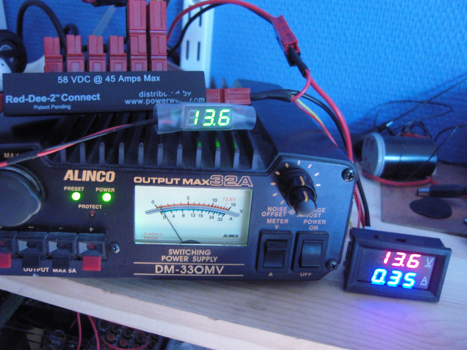
To the right you’ll see my combined voltage and current meter as well as my volt-meter on top of the power supply.
Both of the modules have been bought on Ebay:
- Miniature 0-30 V DC LED 2 wire Digital voltmeter (371333527599) where the display is 22 by 10 mm. Cost slightly more than $1
- 0-100 V, 0-10 A Dual Voltmeter Ammeter (262455987311) costing less than $3. The module size is 48 x 29 x 26 mm and the letters are 7 mm tall just like the miniature voltage display.

DIY Powerpole voltage and current meters
Powerpole voltage and current monitoring is quite nice to have. One can buy commercial meters, but due to the availability of nice and cheap modules, it is very easy to make them oneself.
To the right you’ll see my combined voltage and current meter as well as my volt-meter on top of the power supply.
Both of the modules have been bought on Ebay:
- Miniature 0-30 V DC LED 2 wire Digital voltmeter (371333527599) where the display is 22 by 10 mm. Cost slightly more than $1
- 0-100 V, 0-10 A Dual Voltmeter Ammeter (262455987311) costing less than $3. The module size is 48 x 29 x 26 mm and the letters are 7 mm tall just like the miniature voltage display.
- Related post: “New gadget measures negative resistance“
Improved GPS reception with a ground plane

My poor-man’s 10 MHz reference based on the Ublox Neo-7M GPS module didn’t always receive GPS satellites reliably enough. Since I rely on reception indoors, conditions were sometimes too marginal to lock the oscillator output to 10 MHz. Inspired by the QRPlabs GPS module of Hans Summers (G0UPL) with its large 6 x 6 cm PCB groundplane, I therefore decided to do something similar.
It definitely helped make indoors reception in my shack much more reliable. The first picture shows the unit with the 8.5 x 6.5 cm single-sided PCB ground plane attached with double-sided tape. The picture below shows it prior to adding the ground plane. I also added a small LED to the right so that I could see from the outside whether the GPS locks properly.
This post is a continuation of these other posts about the 10 MHz reference:
- Just good enough 10 MHz reference (3 Oct 2015)
- Better with SMA (15 Oct 2015)
- Curing amnesia in the 10 MHz GPS reference (19 Nov 2015)
Improved GPS reception with a ground plane
My poor-man’s 10 MHz reference based on the Ublox Neo-7M GPS module didn’t always receive GPS satellites. Since I rely on reception indoors, conditions were sometimes too marginal to lock the oscillator output to 10 MHz. Inspired by the QRPlabs GPS module of Hans Summers (G0UPL) with its large 6 x 6 cm PCB groundplane, I therefore decided to do something similar.
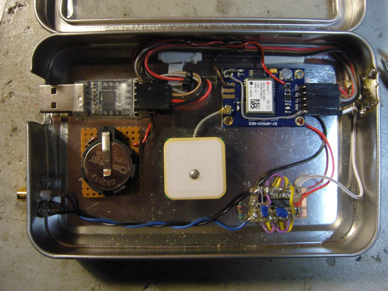
The first picture shows the unit with the 8.5 x 6.5 cm single-sided PCB ground plane attached with double-sided tape. It definitely helped make indoors reception in my shack much more reliable. In addition to the improved conditions for the patch antenna, it probably helps too that the antenna now is shielded from the digital circuitry of the GPS module, the 10 MHz pulse shaper, and the USB interface. I also added a small LED to the right so that I could see from the outside whether the GPS locks properly.
The second picture shows the interior prior to adding the ground plane.
This post is a continuation of these other posts about the 10 MHz reference:
- Just good enough 10 MHz reference (3 Oct 2015)
- Better with SMA (15 Oct 2015)
- Curing amnesia in the 10 MHz GPS reference (19 Nov 2015)
Teeth marks in the K3

DX-expeditions love their K3s. And I love my K3. But look closely at the MENU button and you will find the marks of someone who literally have put the K3 on their menu as well.
Neither has the BAND button escaped this. Judging from the size of the teeth marks it is perhaps not so hard to guess who did this.
This is our club station’s K3 and off weekends the only inhabitants there are mice, who seem to have taken their fancy on the soft buttons of the K3. They let every other piece of equipment alone, such as the Yaesu FT-1000MP, so there is definitely something special about the K3. I would guess that this was not part of the original Elecraft design specifications for these buttons. The remedy is shown here: A custom-designed acrylic cover that is fitted on the K3 whenever it is not in use.
This article originally appeared on the LA3ZA Radio & Electronics blog.
Teeth marks in the K3
DX-expeditions love their K3s. And I love my K3. But look closely at the MENU button and you will find the marks of someone who literally have put the K3 on their menu as well.
Neither has the BAND button escaped this. Judging from the size of the teeth marks it is perhaps not so hard to guess who did this.
This is our club station’s K3 and off weekends the only inhabitants there are mice, who seem to have taken their fancy on the soft buttons of the K3. They let every other piece of equipment alone, such as the Yaesu FT-1000MP, so there is definitely something special about the K3. I would guess that this was not part of the original Elecraft design specifications for these buttons.The remedy is shown here: A custom-designed acrylic cover that is fitted on the K3 whenever it is not in use.
This article originally appeared on the LA3ZA Radio & Electronics blog.


