Author Archive
 Series capacitors that failed according to the book
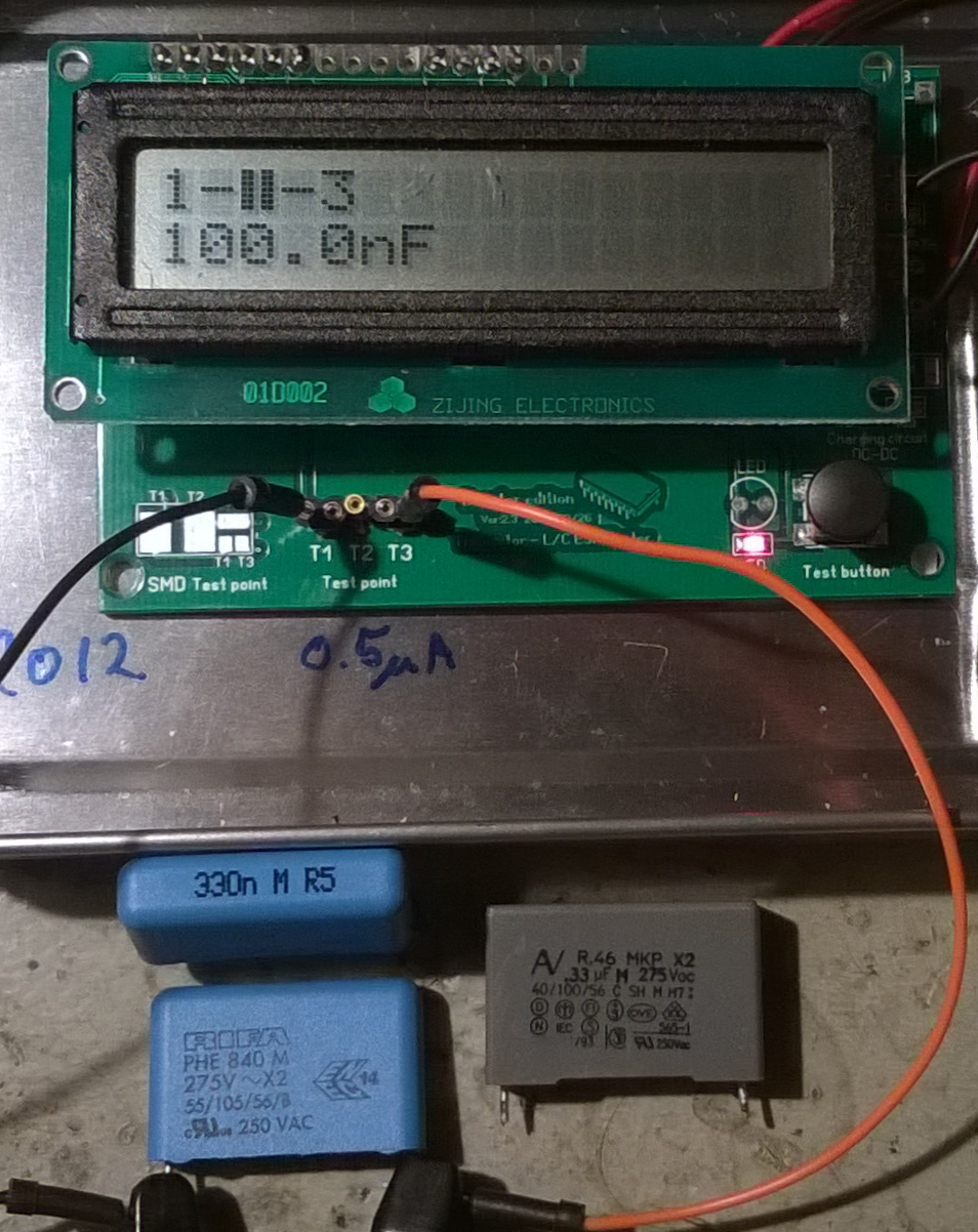 |
| 0.33 uF X2 capacitors which measured only 0.097, 0.1, and 0.118 uF. |
Many devices now use a capacitor power supply saving the space that a mains transformer occupies. The principle is that a series capacitor from the mains supply is used to drop the voltage and reduce the current. Provided that the circuit is completely isolated from human touch, this is an economical way to provide DC power.
The image shows three such capacitors as I were measuring them. They came from three malfunctioning devices in my home: two wall-mounted thermostats for floor heating and a remote controlled mains switch.
Their power supplies were designed with a capacitor of 330 nF in series with a bridge rectifier which supplies the low voltage DC. This value is typical, it seems for 230 Vac, 50 Hz circuits that are designed for about 20 mA. The value will be higher for an equivalent 115 Vac, 60 Hz circuit.
The malfunctioning happened because the value of the capacitor in my cases was reduced to 1/3 and less of the nominal value. These capacitors are all marked X2 and a voltage of 275 Vac.
The X2 means that they are safety capacitors which will not fail by short-circuiting as this would be a fire hazard in this circuit. They have self-healing properties and that means that they fail by “burning away” on their own foil, leading to a reduction in capacitance and eventually failure of the circuit as the power supply cannot supply the required current any more. They should never be replaced by anything but X2 capacitors with the same or higher voltage rating.
Go to the Wikipedia page Capacitive power supply for more description of this circuit.
By the way, the devices which these capacitor came from were 15 year old Microtemp MTN-1991 thermostats and a 20 years old Nobø System 500 RCE512 remote receiver.
Series capacitors that failed according to the book
|
| 0.33 uF X2 capacitors which measured only 0.097, 0.1, and 0.118 uF. |
Many devices now use a capacitor power supply thus saving the space that a mains transformer occupies. The principle is that a series capacitor from the mains supply is used to drop the voltage and reduce the current. Provided that the circuit is completely isolated from human touch, this is an economical way to provide DC power.
The image shows three such capacitors as I were measuring them. They came from three malfunctioning devices in my home: two wall-mounted thermostats for floor heating and a remote controlled mains switch.
Their power supplies were designed with a capacitor of 330 nF in series with a bridge rectifier which supplies the low voltage DC. This value is typical, it seems, for 230 Vac, 50 Hz circuits that are designed for about 20 mA. The value will be higher for an equivalent 115 Vac, 60 Hz circuit.
The malfunctioning happened because the value of the capacitor in my cases was reduced to 1/3 and less of the nominal value. These capacitors are all marked X2 and a voltage of 275 Vac.
The X2 means that they are safety capacitors which will not fail by short-circuiting as this would be a fire hazard in this circuit. They have self-healing properties and that means that they fail by “burning away” on their own foil, leading to a reduction in capacitance and eventually failure of the circuit as the power supply cannot supply the required current any more. They should never be replaced by anything but X2 capacitors with the same or higher voltage rating.
Go to the Wikipedia page Capacitive power supply for more description of this circuit.
By the way, the devices which these capacitor came from were 15 year old Microtemp MTN-1991 thermostats and a 20 years old Nobø System 500 RCE 512 remote receiver. They now all work again thanks to the fitting of new 0.33 uF capacitors. And all of them are safety capacitors of type X2 of course – no gambling with safety here.
Latest firmware for AP510 APRS tracker is superb
I got my AP510 APRS tracker a little more than a year ago. It kind of worked, but not very well in my car. But after the tracker got a new firmware dated 3 Nov 2015, it has become so much better. Now I can say that it is really useful.
Apparently, the Smartbeacon function didn’t work properly in earlier versions of the firmware. With some good debugging and error reporting by KC5EVE, Mark, working with the software developer for the AP510, BG6QBV, the annoying errors now seem to be gone. This is all documented in the Yahoo AP510 group.
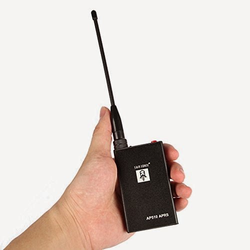
I have fitted mine with a 16-45 cm telescopic antenna and even when attached to one of the rear headrests in my sedan, the 1 Watt of output power tracks very well.
The map below shows a drive from Telemark, about 100 km west of Oslo, to Oslo with as good coverage as one can expect given the valleys and the availability of APRS digipeaters on the way.

Latest firmware for AP510 APRS tracker is superb
I got my AP510 APRS tracker a little more than a year ago. It kind of worked, but not very well in my car. But after the tracker got a new firmware dated 3 Nov 2015, it has become so much better. Now I can say that it is really useful.
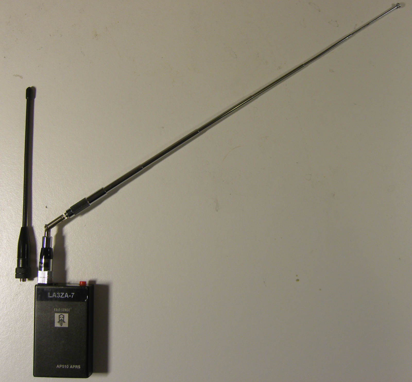 |
| AP510 with original short antenna and telescopic antenna |
Apparently, the Smartbeacon function didn’t work properly in earlier versions of the firmware. With some good debugging and error reporting by KC5EVE, Mark, working with the software developer for the AP510, BG6QBV, the annoying errors now seem to be gone. This is all documented in the Yahoo AP510 group.
I have fitted mine with a 16-45 cm telescopic antenna and even when attached to one of the rear headrests in my sedan, the 1 Watt of output power tracks very well.
The map below shows a drive from Telemark, about 100 km west of Oslo, to Oslo with as good coverage as one can expect given the valleys and the availability of APRS digipeaters especially in the western part.
|
| Note the missing tracks east of LA5PPA-1 which are due to a 3.5 km long tunnel, Strømsåstunnelen, between Drammen and Mjøndalen. |
Magnetospherically ducted echoes in the San Francisco area
On 7. November 2015, several radio amateurs in northern California heard echoes in the 80 meter band. I was made aware of it by Jack, W6FB in Santa Clara, who recorded signals from K6YT some 25 miles away. According to W6FB, the echo effect was also heard north of Sonoma (several hundred miles north of him, reported by N6ZFO).
KM6I, Gordon, in Palo Alto also heard echoes of his own signals and recorded them. In his blog he analyzed the delay from the output of his transceiver and found 157 ms. He found that to be so close to the round-the-world time for signals of 138 ms, that he assumed that to be the cause.
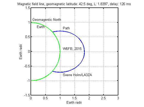
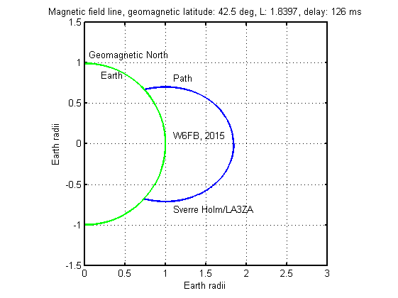
I don’t agree, so I took the location of W6FB at locator CM97ah (Santa Clara) as a starting point for computing delay. This is latitude 37.31 and longitude -121.96 and gives a geomagnetic latitude of about 42.5 degrees. Then I put it into my program for computing path length along geomagnetic field lines assuming a height of the reflecting ionosphere on the opposite side of 100 km. The result is shown in the figure and predicts a delay time of 126 ms. My estimate of uncertainty is +/-5 ms.
The delay value is slightly less than 138 ms and easy to confuse with a round-the-world path. The challenge with estimating delays like this from the signal is that amateur transceivers may have an unspecified delay between start of transmission and start of sidetone. Measuring on the audio output as done here, measures the sidetone, not the actual RF.
I discussed this source of error in my 2009 QST article “Magnetospheric ducting as an explanation for delayed 3.5 MHz signals.” Therefore the measurement shown above may fit with 138 ms just as well as with 126 ms, it depends on the actual transceiver’s delay.
Other properties of the echo such as the amplitude of the echo which according to W6FB at times was louder than the direct signal. This points to the duct theory as the explanation.
Others have heard such echoes also:
- 210-220 ms, G3PLX, November 2006, 160 m. Listen to the signal here.
- 165-168 ms, K4MOG, February 2006, 80 m. Listen to the signal here.
- 214-219 ms, W2PA, February 2008, 80 m.
- 237 ms, OZ4UN, January 2009, 80m, Listen to audio file where also OZ7BQ very close by heard the echoes.
Other posts on the theme: Magnetospherically Ducted Echoes or Medium Delayed Echoes
Magnetospherically ducted echoes in the San Francisco area
On 7. November 2015, several radio amateurs in northern California heard echoes in the 80 meter band. I was made aware of it by Jack, W6FB in Santa Clara, who recorded signals from K6YT some 25 miles away. According to W6FB, the echo effect was also heard north of Sonoma (several hundred miles north of him, reported by N6ZFO).
KM6I, Gordon, in Palo Alto also heard echoes of his own signals and recorded them. In his blog he analyzed the delay from the output of his transceiver and found 157 ms. He found that to be so close to the round-the-world time for signals of 138 ms, that he assumed that to be the cause.
I don’t agree, so I took the location of W6FB at locator CM97ah (Santa Clara) as a starting point for computing delay. This is latitude 37.31 and longitude -121.96 and gives a geomagnetic latitude of about 42.5 degrees. Then I put it into my program for computing path length along geomagnetic field lines assuming a height of the reflecting ionosphere on the opposite side of 100 km. The result is shown in the figure and predicts a delay time of 126 ms. My estimate of uncertainty is +/-5 ms.
The delay value is slightly less than 138 ms and easy to confuse with a round-the-world path. The challenge with estimating delays like this from the signal is that amateur transceivers may have an unspecified delay between start of transmission and start of sidetone. Measuring on the audio output as done here, measures the sidetone, not the actual RF.
I discussed this source of error in my 2009 QST article “Magnetospheric ducting as an explanation for delayed 3.5 MHz signals.” Therefore the measurement shown above may fit with 138 ms just as well as with 126 ms, it depends on the actual transceiver’s delay.
Other properties of the echo, such as the amplitude of the echo which according to W6FB at times was louder than the direct signal, also point to the duct theory as the explanation.
Others have heard such echoes also:
- 165-168 ms, K4MOG, February 2006, 80 m. Listen to the signal here. This event is also the object of the analysis in my QST article referenced above.
- 210-220 ms, G3PLX, November 2006, 160 m. Listen to the signal here.
- 214-219 ms, W2PA, February 2008, 80 m.
- 237 ms, OZ4UN, January 2009, 80m, Listen to audio file where also OZ7BQ very close by heard the echoes.
- About 200 ms, G3ZRJ, January 2012, 80m. Also heard by GW3OQK, 100 km apart.
Other posts on the theme: Magnetospherically Ducted Echoes or Medium Delayed Echoes
Finally got rid of the pirated USB chips for the UV-5R and the AP510

Both the Baofeng UV-5R handheld UHF/VHF radio and the Sainsonic AP510 APRS tracker come with interface cables with pirated chips. These are clones of Prolific USB/serial chips. Since Prolific has taken measures against this, only old drivers will work with them. That means that one has to stop automatic driver updates as explained on the Miklor site for the Baofeng UV-5R. The same is true for the AP510. This is a nuisance.
I got tired of this and got myself some USB/serial modules from Ebay based on the CP2102 chip instead. The cost was US $1.43 a piece so it should be affordable for anyone. I also got some clear heat shrinkable tube.
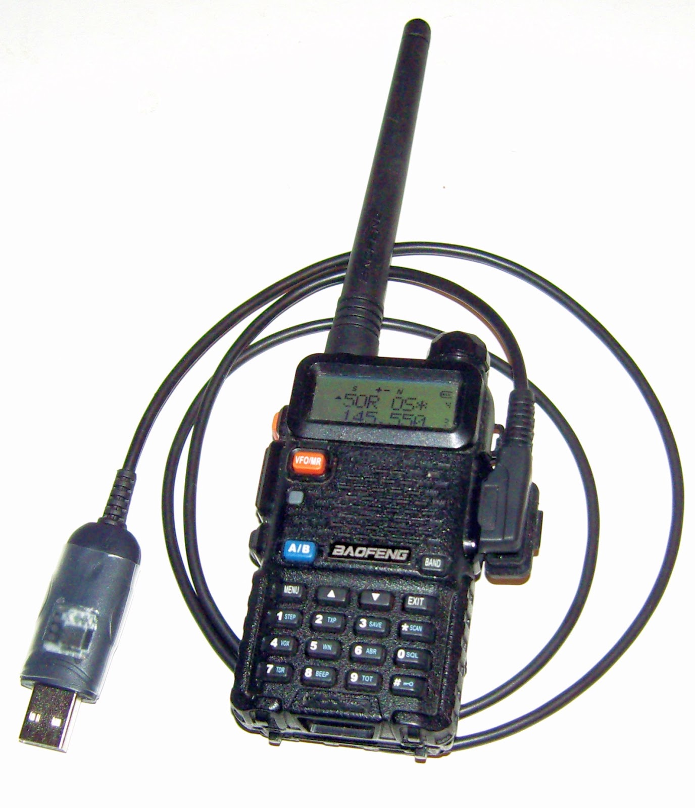
It wasn’t too hard to follow the instructions on the Miklor site. I ended up replacing the chip in the original Baofeng serial cable. I’m a hardware guy so I think it is a shame not to see the three LEDs for power, rx, and tx so I used my Dremel to make a 12×12 mm cut-out in the original case, and then I closed it by using transparent shrinkable tube. For a picture, see the top of the first image.
If it doesn’t work the first time, exchange rx and tx and see if that works better. According to this site, the boards can be marked just opposite of what you might think.
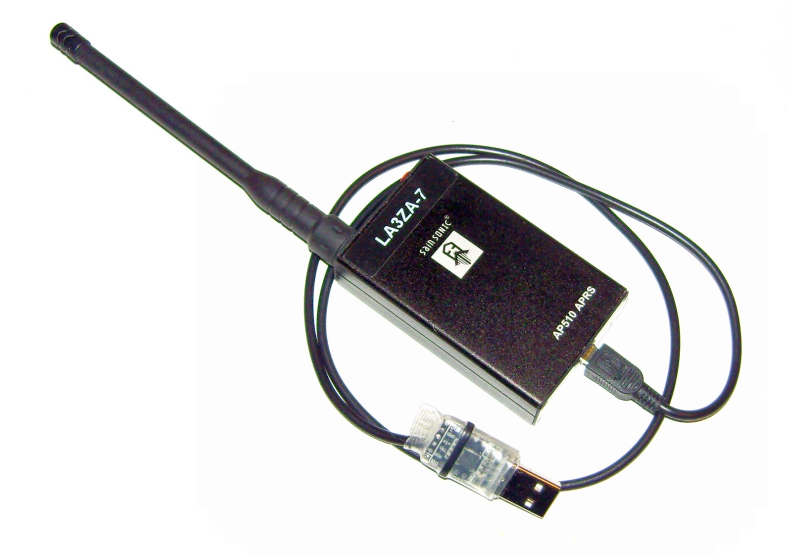
The Sainsonic AP510 APRS unit has a cable that on first sight just looks like a standard USB cable, but it also contains such a chip. Here I made a completely new cable without any case. It is important that 5 Volts also passes through as this is used for charging. The pinout can be found on the site of DJ7OO (use Google translate if needed). I enclosed the board in shrinkable tube which is transparent enough for the LEDs to shine through as seen in the bottom of the first image. The board with the fake chip is found in the middle.
 So now I have interface cables for both units that don’t require me to stop updates of drivers or any other special precautions and it is much easier to program the devices from any PC.


