Posts Tagged ‘WSPR’
 Whispering with a VCXO-AXE
My VCXO-AXE WSPR transmitter kit from W5OLF came this morning. It was two weeks in the post, doubtless due to Customs which had opened the package. I wasted no time in building it, though it did take me somewhat longer to complete than it took AE5X.

The kit itself has been impressively put together. The PCB is extremely high quality and the instructions are almost of Elecraft standard. If the horrible Spectrum Communications Off-Air Frequency Standard kit had been produced to this level of quality it might not have turned out to be a failure for me. If American kit makers can produce nice silk screened and solder masked boards, why do ours make us struggle with boards that look like they were made by hand on somebody’s kitchen table?
The VCXO-AXE kit uses almost all through hole components and there is plenty of space around the solder lands. I doubt that anyone would have any trouble building this. The one part that induced a feeling of terror when I saw it was the VCXO itself.
As described, it is a “larger surface mount component.” But what I didn’t expect was that it didn’t have any pins or legs that stick out to solder to. Instead, you have to solder it so the solder goes under or up the side of the chip. You need a very fine tipped soldering iron for this. I couldn’t really see if I had successfully soldered the chip or not, so I took a couple of pictures.
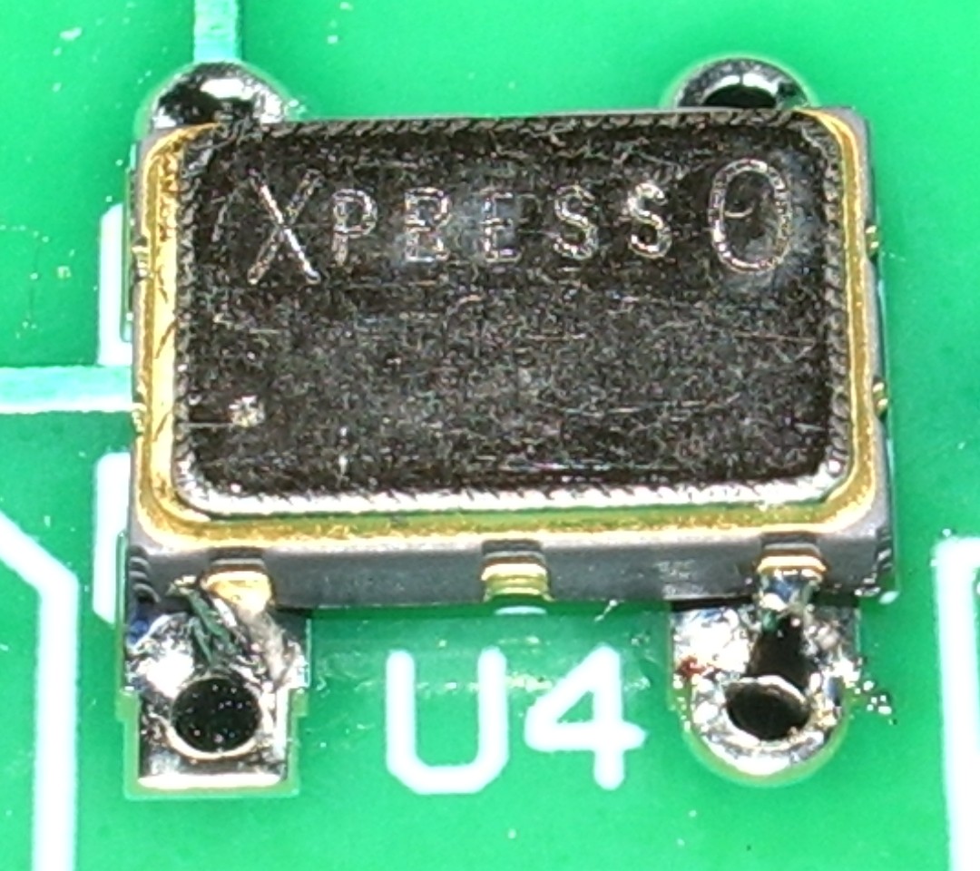
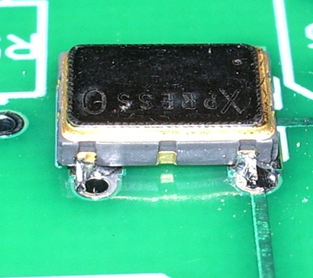
The result is not very pretty, but it must have been OK because the transmitter eventually worked!
When ordering, I specified my call, locator and the supply voltage I would be using (12V, as I planned to power the transmitter off a pack of 10 NiMH batteries.) The PICAXE controller chip came programmed with this information and a power level of 33dBm – 2 watts.

On a freshly charged battery pack I was actually getting nearer 3 watts output once the PA tuning capacitor had been peaked up, but after the first few transmissions the power did drop off a bit to become nearer the advertised 2 watts.
I hooked the VCXO-AXE up to my attic MFJ magnetic loop, watched the radio-controlled clock in the shack until it rolled over to an even minute, pressed the transmit button and a couple of minutes later had my first WSPR spots.
Soon after that I had several more. No great DX, but perhaps that is just down to conditions at the moment.
The instructions warn that second harmonic suppression of this transmitter is not great and an external low pass filter is advised. However, the magnetic loop (either the MFJ or my portable Wonder Loop) has a very high Q which I am sure does a good job of attenuating out of band harmonics on its own.
My next move will be to build the little transmitter into a plastic box and use it as a hand held portable WSPR rig. It would be fun to try making a 30m base loaded whip – which should also be fairly high Q – and see how well that works. So expect some WSPRing from various locations around Cockermouth some time soon!
This was a fun project and a good morale booster to prove to myself that I can still build stuff – and with an SMT part in it, too! Thanks to Jay W5OLF for making the kit available. A 20m version would be nice, as well!
If you want to buy one of these kits for yourself you have to look on eBay, though as of right now there doesn’t seem to be any for sale.
Whispering with wonder
A few days ago I dug out of the cupboard the Wonder Loop portable magnetic loop that I made a while ago. I had lost the pieces of uPVC electrical conduit that made a Heath Robinson support for the coaxial cable loop element. But I had always felt the saggy coaxial loop was a bit of an eyesore anyway. So I decided to make a new loop using microbore copper tubing. It turns out that you can buy this stuff on eBay – any diameter and length that you want shipped to your door next day by first class post. Three metres of 1cm dia tube cost just over £12.

The new loop looks a lot better and certainly hasn’t harmed the performance of the antenna which continues to amaze me. I tested it using WSPR at a 1W power level on all bands (40m – 15m) that my Wonder Loop covers. The best result was obtained yesterday afternoon on 20m, between 16:30 and 19:38z, when I received 15 reports from VK2XN of from -9 to -25dB SNR, at a distance of 16579km. This, I repeat, was using just 1 watt from the FT-817 with the Wonder Loop sat on my shack “workbench” almost exactly as in the picture. (The FT-817 was moved to the radio/computer desk during transmission.)
I also spotted 9 reports of VK2XN during the same period, which surprised me due to the extremely high noise level I have here on 20m. The SNRs weren’t so good, though, and he was running 10 watts. Still, that almost qualifies as a two-way contact.
I haven’t tried other modes yet, mainly because the shack is so small and these days I’m a bit wary about sitting inches from an antenna even if it is radiating no more than a watt or two. But the original Wonder Loop was very successful using PSK31 and I hope to try this one with JT65A shortly.
The one disadvantage of the new copper loop is that it isn’t exactly portable, which had been one of my original objectives when building the antenna. If you could get hold of some metal strip it might be possible to make the loop from six pieces that you can join together using bolts and wingnuts to form a hexagon. Possibly you could even do this using tubing, flattening the ends of each 60 degree segment and then drilling them so the loop could be bolted together. But as I’m not planning on taking the antenna anywhere at the moment I’ll keep the one-piece loop which I can stick behind the shack door for storage.
This is a really great antenna that should enable anybody to operate HF from anywhere.
K2 audio switchbox
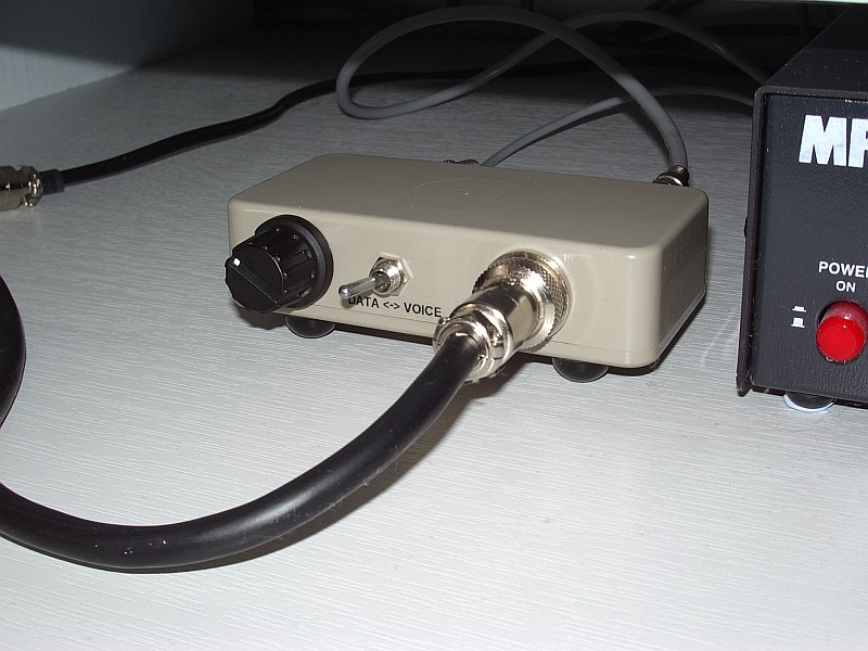
My vision and steadiness of hand have improved to the point that I am able to build projects! Here is a picture of a switchbox I made for my Elecraft K2 a couple of days ago which allows me to switch the audio input source from the microphone to the computer sound card.
One of the niggling annoyances of the K2 is that it does not have separate inputs and outputs for voice and data modes. Most users carry out one of several published mods to obtain a fixed level audio output for the computer. Mine is tapped off the KAF2 filter module and runs to an RCA phono socket on the back panel. But for transmit most people just swap the mic lead and data lead over.
I used my K2 like that for years, though it wasn’t a great hassle mainly because I hardly ever used a microphone anyway. But I finally decided to come up with a better solution – hence the switchbox. It was easy to make and I thought it would be within my capabilities. Here is a picture of the internals.
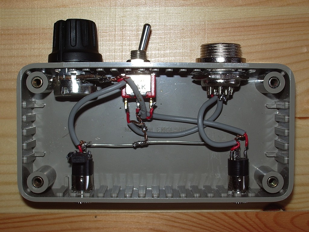
In one position of the front panel switch the microphone signal is switched straight through. In the other, the audio comes from the computer sound card headphone output via a potentiometer. Since taking that picture I added some resistance to the hot side of the pot so the control can be used over a greater range as the K2 mic input is very sensitive and needs some attenuation. As you can see, I don’t bother with isolating transformers. I’ve made dozens – well at least a handful – of computer/radio interfaces in my time and I have never, ever found the need for one. YMMV.
To celebrate the restoration of my constructional skills I have ordered a W5OLF WSPR beacon kit. John Harper, AE5X, recently reviewed it and wrote that it took him 50 minutes from starting to build to receiving his first spot. So I figured it shouldn’t be too difficult, though it will probably take me longer than 50 minutes. It would be nice to successfully complete a kit before I start undergoing the treatment that I expect will make me too tired to do all the stuff I am managing to do at the moment.
You can count on WSPR
 |
| 10 meters |
 |
| 15 meters |
 |
| 20 meters |
Life on 6m
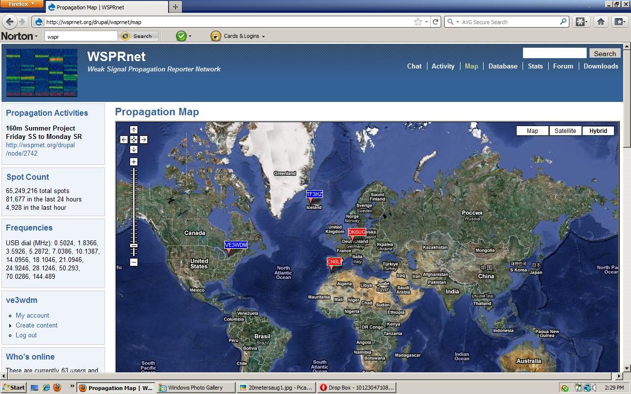
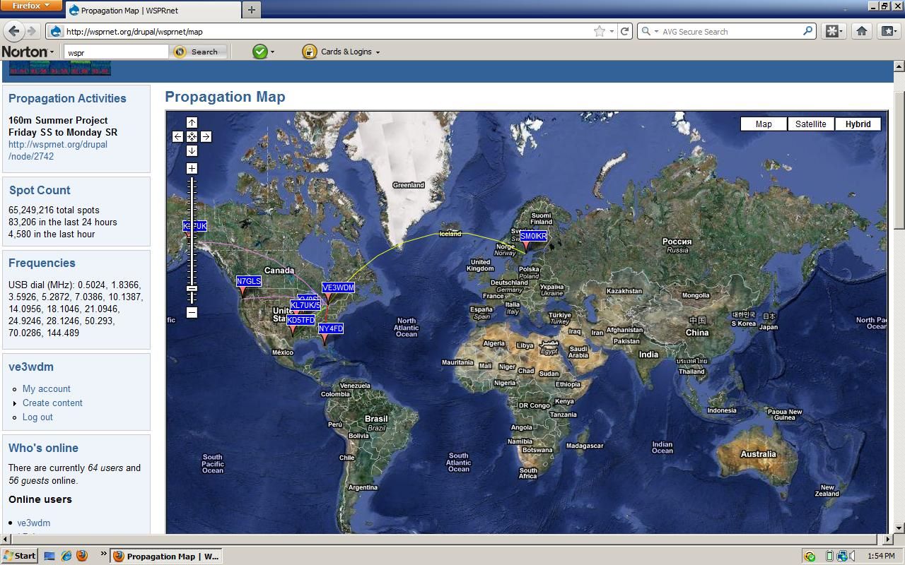
The 6 metre band is showing signs of life, as this map of WSPR activity from this afternoon shows.
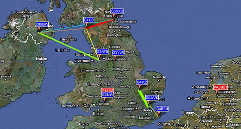
However, some of the traces on the WSPR application screen look a bit odd.

I don’t claim to be an expert but I think what I am seeing is the result of doppler shift on the signals being reflected by fast-moving Sporadic-E clouds. In several cases what seems to be a trace has not been decoded.
I’ve said this before, but I wonder if WSPR mode with its 110 second transmit periods and tiny frequency shift encoding is really suitable for detecting Sporadic-E propagation. But no-one has ever commented on this, leaving me to wonder whether they think I’m an idiot who doesn’t know what he is talking about or whether nobody knows.
The digital mode most people seem to use on 6m is JT6M, however this entails using the WSJT program which I find rather confusing. I’m interested in trying JT65A but I’m not sure if it is any more suitable than WSPR for this type of work.
In the absence of any expert advice I’m going to try JT65A using a dial frequency of 50.276MHz. With the JT-Alert accessory to tell me when anyone replies I can leave the rig calling CQ whilst I am otherwise occupied. It will be interesting to see what we can work on 6m with the JT65A mode.
Life on 6m
The 6 metre band is showing signs of life, as this map of WSPR activity from this afternoon shows.
However, some of the traces on the WSPR application screen look a bit odd.
I don’t claim to be an expert but I think what I am seeing is the result of doppler shift on the signals being reflected by fast-moving Sporadic-E clouds. In several cases what seems to be a trace has not been decoded.
I’ve said this before, but I wonder if WSPR mode with its 110 second transmit periods and tiny frequency shift encoding is really suitable for detecting Sporadic-E propagation. But no-one has ever commented on this, leaving me to wonder whether they think I’m an idiot who doesn’t know what he is talking about or whether nobody knows.
The digital mode most people seem to use on 6m is JT6M, however this entails using the WSJT program which I find rather confusing. I’m interested in trying JT65A but I’m not sure if it is any more suitable than WSPR for this type of work.
In the absence of any expert advice I’m going to try JT65A using a dial frequency of 50.276MHz. With the JT-Alert accessory to tell me when anyone replies I can leave the rig calling CQ whilst I am otherwise occupied. It will be interesting to see what we can work on 6m with the JT65A mode.
Time to ditch Dimension 4
Digital modes such as WSPR and JT65A are time-synchronous and require the computer clock to be accurate to within a second. New users frequently don’t realize this and find that they aren’t decoding any signals. When they go to a forum for advice they are inevitably advised by well-meaning helpers to run a bit of software called Dimension 4.
Once upon a time there may have been a good reason for using this program but today it is not a good idea at all. I have seen several forum threads where people have installed Dimension 4 and believed that their PC clock was now accurate, but were still not decoding signals. I suspect that this is because newer versions of Windows have tightened the security controlling whether programs are allowed to do things like change the system clock. Dimension 4, being last updated in 2004 according to its website, knows nothing of this.
There may or may not be ways to make Dimension 4 work under Windows 7 or Vista but there is no reason to bother with them. Instead, just install Meinberg NTP for Windows. Not only is this every bit as free as Dimension 4, it is also the official Network Time Protocol client software. Nothing is ever going to keep your computer clock more accurate than this, and if installed using the default settings it will “just work” even on the latest versions of Windows.
So please, computer Elmers, stop telling people who need to get their clocks synchronized to install an old and unsupported program.


