Posts Tagged ‘workbench’
 International Radio Restoration Contest
I have recently been made aware of the Socété Québécoise des Collectionneurs de Radios Ancien's / (SQCRA or Quebec Antique Radio Collectors Society) 'Radio Restoration Contest' and have been enjoying some of the published documents describing various refurburations.
Although the group has been sponsoring the refurb contest for over 10 years, this is only the third year that it has been open to international competition. The rules are interesting and are quoted from the SQCRA website:
" ... participants have one year to restore a basket case radio (the worst it is at start, the more points are awarded for the difficulty). Pictures must be taken before the restoration starts and at all steps of the process. One year later, the participants present their work to the international panel of judges. Pictures taken during the process will help judges better understand the challenges faced by the participants in order to finish their project.
The clubs that don't have a contest can nominate someone or make a group effort to represent their club at this contest.
A documented report containing photos and explanations and optionally a video of the working set from each contestant must be submitted to us. Then judgement and results are compiled to determine a winner and two runners up.
A documented report containing photos and explanations and optionally a video of the working set from each contestant must be submitted to us. Then judgement and results are compiled to determine a winner and two runners up.
The criteria's for evaluation are available in this document .
Our goal of course is to promote the conservation of the technological / historical heritage, to motivate our common interest, increase the general knowledge of ancient radio technology, gain restoration tips, increase club exchanges, and see what is done in other clubs."
Each project is judged on three basic criteria: difficulty (condition when found), restoration (chassis, cabinet, components, overall) and functionality when complete.
The present contest has just ended (March 15) but the judge's comments and project writeups from the previous two contests (as well as this year's project writeups) are available for reading ... and they are both instructive and inspirational as I found several new constructive hints embedded in the descriptions.
Particularly interesting to me was the sidebar in the writeup article presented by Gerry O'Hara of B.C.'s SPARC Museum. I have been struggling to develop a method of building this period-correct component for several years and the solution looks elegantly simple!
 |
| courtesy: http://www.sqcra.org/ |
There really is enough reading here to keep one entertained for days but the more I read, the more I want to find another old clunker and bring it back to life ... great stuff!
’29 MOPA – Small Step
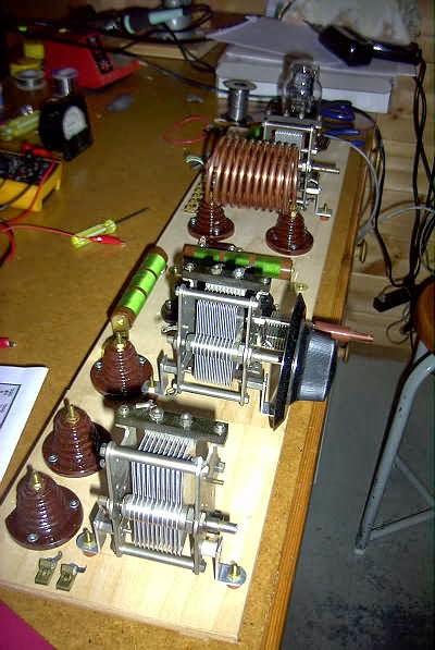 This morning I completed the wiring of the test-bed MOPA's Hartley oscillator circuit. I was using the 80m tank at the time, wound with 3/16" copper tubing. Oscillator keying is about what I expected ... stable but with some ripple on the note. Even with DC on the filaments, many of these open-breadboard oscillators suffer from RF-modulated notes. Sometime wrapping the power supply or keying leads in a ferrite toroid help or eliminate the slight rasp. On the other hand, some builders prefer to have a note that sounds more '29-like, as in all likelihood, not many notes sounded like pure DC back in the day.
I'm really having second thoughts about my construction method and may just jump to the next (final) construction phase rather than slog through completion of the test-bed model. I've already learned much about the layout by getting to this stage and the extra work involved in completing the test-bed model may not tell me anything new.
I'm using a VT-25 version of the somewhat pricey and hard-to-find type '10' tube. The final version will be built in a similar fashion to my Tri-Tet-Ten, on an aluminum sheet atop the breadboard. Hopefully having the groundplane and shorter leads, will lead to a cleaner note in the final version.
I'm rather dreading this next final phase as there is little room for error. The aluminum sheet must be precisely pre-drilled, as well as the breadboard, and protected at all times (especially when making soldered connections) to prevent any finger marks or scratching on the aluminum sheet. There are still several drilling details to be worked out before I can move forward.
BK Bustle
You may hear plenty of activity in the nights leading up to the Party as various stations burn the cobwebs out of their handmade creations around 3550-3570 in the next few nights...you might give them a call if you hear them as most will be delighted to know that they're getting out of their backyard.
A few weeks ago, in the same spirit of preparation, I began work on a small amplifier for my Hull Hartley transmitter. Ever since entering the BK Party, I have been held hostage by the monster winds which always seem to show up here during early December. Self-excited oscillators connected to blowing antennas create an unusual-sounding signal...somewhat musical....up to about 30km, but after that, somewhat dreadful, as shifts in frequency between keying elements can be measured in tens of Hertz or more and make it difficult to copy a weak signal.
I put the amp together in the original 'ugly construction' style of the 20's, which I'll call 'ugly breadboard'. For the most part, period-appropriate components were used, as it was to be a 'proof-of-concept' project....to see if and how it would work and what changes might need to be implemented in a 'finished' version.
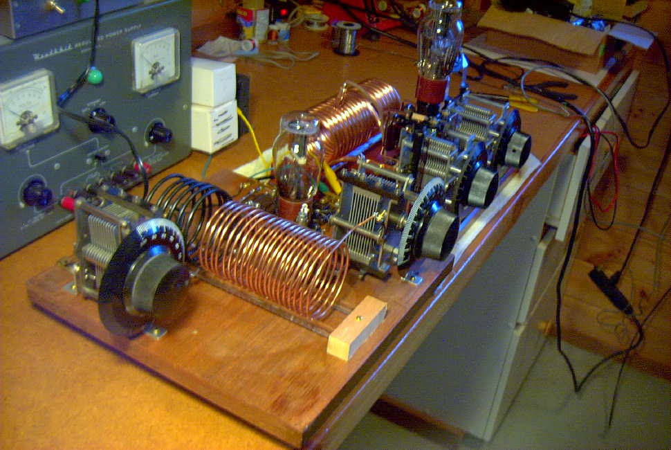 t t |
| Amplifier stage followed by Hull Hartley exciter on far end. |
The original circuit, shown below, was published in the February 1931 QST and penned by George Grammer (W1DF), the ARRL's Assistant Technical Editor. Since I already had the oscillator section, I built the amplifier only, making a few modifications.
 |
| Courtesy: http://www.arrl.org/ |
My changes involved removing the B+ from the exposed plate tank coil by putting C7 between the plate and the tank circuit, grounding the coil tap point and shunt-feeding the B+ directly to the plate. As well, the operating bias was changed from the original combination of grid-leak and external fixed-bias (always a pain) to grid-leak bias only. Since I planned to let the oscillator run and key only the amplifier stage, no external (extra) bias was needed. The original system of feeding drive via capacitive coupling from the oscillator tank circuit was maintained as was the 'plate neutralizing' system. With the plate tank no longer carrying B+, a wide-spaced variable capacitor was no longer required for C3. These changes are illustrated below:
 |
| Courtesy: http://www.arrl.org/ |
Testing went smoothly and with the help of a tuned RF-sniffing wavemeter (the actual one I built when I was a brand new15 years old ham!), the amplifier neutralized beautifully. It was unconditionally stable, in spite of the numerous clip leads surrounding the board connecting to the separate Hartley oscillator in a somewhat haywire fashion....it really was a mess. As one other '29 builder (KK7UV) so perfectly described his latest workbench project, it "looked like the transmitter was on life-support!"
Surprisingly little drive was required from the Hartley and it was run at just 200VDC. The amplifier efficiency was around 50% which could probably be improved upon with careful attention to biasing values, shorter leads and more efficient antenna coupling. On 80m, the only band that I wound a coil for, keying was clean and very nice (an advantage of being able to run the oscillator at low level). Without too much effort, 15 watts out was easily obtained...far too much for the BK Party.
Tapping down on the tank coil for 40m operation proved to be a different story as the note sounded like a buzz saw...very raspy and nasty. To really undertake a fair test, a dedicated 40m tank coil would have to be used as well as a much 'cleaner build'.
The rat's nest of unwanted coupling of both RF and AC ripple was showing through on this higher frequency.
For multiband operating events, such as the BK, things have to be efficient enough to make band changing and tune-up procedures quick and simple and in its present haywire form, the amplifier would just not be 'contest-friendly'.
All in all it was a very valuable building exercise as a LOT was learned. I am now convinced that for a true MOPA (Master Oscillator Power Amplifier) combination to do what is needed will require an all-in-one style of construction....both oscillator and amplifier on the same board, with short leads and little chance for unwanted parasitic-coupling between stages. With separate coils for all bands and calibrated dials, tuning and changing bands would be very much easier than trying to couple two separate units together. I can see why the struggle to get the original '29ers away from their simple Hartley's and TNT's and over to MOPAS went on for several years.

So once again I am at the mercy of the wind-gods and hoping for two back-to-back Saturdays of quiet BK-friendly air...in early December...on the west coast...by the ocean...yeh, right!
More Resistors From China
 I suspect that, overall, very few hams actually take the time to read ham radio blogs. Of those that do, there is probably only a small percentage that take the time to read any post-blog 'comments' that might be made by others....so...if you missed the comments regarding my recent e-Bay resistor purchase, the following information may be of interest.
Steve, G1KQH, commented that he had found an even better deal on resistors from China at Banggood, in Guangzhou. I have heard good things about this company, which sells a large variety of items from electronic parts to the latest quadcopters. Steve reported a good buy on 1%, 1/4W resistors...50 different values and 50 of each....2500 resistors in total. The offering may be found here.
 |
| Courtesy: Banggood.com |
Steve adds: "The values of resistor are: 10M ,4,7M, 2M, 1M, 390K, 330K, 300K, 220K, 200K, 180K, 150K, 100K, 82K, 68K, 47K, 33K, 37K, 20K, 18K, 15K, 10K, 9K1, 8K2, 6K8, 5K6, 4K3, 3K9, 3K3, 3K, 2K7, 2K4, 2K, 1K5, 1K2, 1K, 680R, 470R, 300R, 270R, 180R, 91R, 68R, 56R, 47R, 20R, 10R, 6,6R, 1,8R, 1,2R , 1R.
They are five banded resistors inc one for the tolerance.
Arrived quick and you can use Paypal on Banggood, so no problem getting your money back if things go wrong."
With the free shipping, this is a super price and could be very difficult to beat! In addition, they offer smaller 1/4W resistor kits, a nice kit of 1/2W resistors, SMD kits and capacitor kits.
G1KQH maintains an interesting amateur radio blog, well worth a read. Thanks for the info Steve.
’29 Style Transmitters…What To Build? – Part 2

When it comes to putting a transmitter together for the BK, there are a lot of choices! My advice for a first-build '29 rig would be either a simple TNT or a Hartley-style oscillator. Both are easy to get operating and, when correctly optimized, are capable of putting out a nice-sounding signal.
For a first-time build, with the main objective being to have something ready in time for the December BK, I would not be concerned about overall appearance or period-appropriate parts. For now, the only thing that must be period-appropriate is the tube...improvements can come later.
As well, I would not be overly-concerned about running the maximum power of 10W input. If you are able to get a type '10' or the equivalent VT-25, or a pair of 45's, then the legal-limit is easily within reach. Utilizing something smaller, at just a few watts output, should not be considered a deterrent, as BK-operators all seem to have very good ears. Just 2 or 3 watts will guarantee plenty of contacts no matter where you are located!

Shown above is a fine little TNT built by Kevin, WB2QMY, in New York. It uses a very affordable UX-201A triode, originally manufactured in 1925 for radio receivers. Although Kevin's TNT puts out barely 2 watts on 80m CW, we had no trouble working each other in a recent BK QSO Party. If you build it, they will come!
If you prefer to tackle a TNT, here is the information you will need. This circuit appeared for several years in the ARRL Handbook's transmitter-section. I suspect that it was probably built by thousands of young hams in the late 20's and early 30's and affordably introduced most of them to the magic of radio. For more building details, including how to keep high-voltage off of the main tank coil, see the information on my website describing the TNT project.
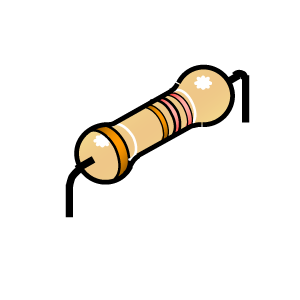
Should you be interested in tackling a Hartley, here is an interesting circuit described by Nick, WA5BDU.
 |
| Courtesy: WA5BDU |
Such a transmitter would readily lend itself to a parallel arrangement of two or more triodes, such as the 27 or the 45 and would develop good power levels inexpensively.
ABØCW has designed a Hartley oscillator using a pair of 27's in parallel and uses them to drive a small amplifier. As described on his website, the oscillator would make a fine stand-alone transmitter with a simple link-coupling antenna circuit.
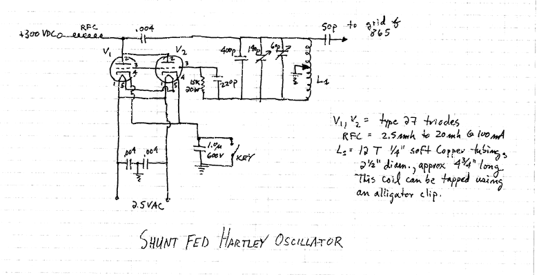 |
| Courtesy: ABØCW |
You can find a list of '29-style related building links, as well as a gallery of transmitters constructed by others, at the bottom of my TNT web page here.
And....circuit ideas, help with parts and lots of BK-chat can always be found at the Yahoo AWAGroup where the focus is mainly on building and operating.
’29 Style Transmitters…What To Build? – Part 1
 Most hams in the late 20's and early 30's seemed to be using simple transmitters...one or two tubes at the most. No doubt the poor economics of the time made it difficult to build anything really elaborate but it didn't seem to stop them from getting on the air with whatever they could put together.
New rules for amateur radio signal stability came into effect in 1929, making that a pivotal year for amateurs, resulting in several new ideas for 'modern' transmitters hitting the publications of the day.
All of the simpler, one-tube transmitters, were self-excited oscillators capable of pretty good sounding signals when operated correctly and when the wind wasn't blowing the antenna around. Being directly-coupled to the antenna meant that any variations in antenna impedance caused by antenna wire movements, would result in the note rising or falling in frequency by several hertz with the resultant 'musical-sounding' note. You can usually hear lots of these during the windy winter BK Party!
From what I can determine, the most popular first-time transmitter was the one-tube TNT (Tuned-Not-Tuned) style as it could usually be built with parts stripped from an old broadcast receiver.

With a low parts-count, it was easy on the pocketbook. The grid coil was broadly resonant near the plate circuits frequency, resulting in enough feedback to sustain oscillation. The grid coil really needs to be optimised (a simple procedure) for peak efficiency and note quality. You can listen to the note quality on my own TNT while transmitting on 40m.
The Hartley oscillator is just as easy on the pocketbook as the TNT, and in the opinion of most, capable of an even better-sounding note once properly optimized.
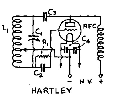
This transmitter is optimized for best note-quality and plate efficiency by finding the correct tap point on L1. Hear my own Hartley's tone while transmitting on 160m.
The third common transmitter of the early 30's was the TPTG (Tuned-Plate-Tuned-Grid).

The TPTG style is a step-up from the TNT and similar in design. Although the added expense of a second variable capacitor made it less popular than the previous two styles, optimizing performance was somewhat easier since the grid circuit could be more readily adjusted for the oscillator's 'sweet-spot' without having to add or remove turns on the grid coil.
All of the triodes mentioned in my previous blog will work well in the above circuits. Keying is normally accomplished as shown below, by connecting the balanced filament resistor on the directly-heated cathode to ground.

It is important to know that construction need not be fancy to get on-the-air for the BK and there is no reason why modern components cannot be used, along with the era-appropriate tube. If you're still undecided, I'll give you some building details to consider next.
Building …. ’29 – Style

Initially this might seem a difficult task, and that was my first reaction when first learning of the vintage operating event. Once I had learned more about these types of transmitters and actually listened to the BK action, I knew that it was something that I really wanted to do. After seeing several inspiring videos from Neil (WØVLZ) and Joe (N2OUV), demonstrating their homebuilt '29 TNT transmitters, I knew it was something that I really had to do! Perhaps the videos will grab you as well:
One of the first things that might seem impossible to obtain would be a suitable tube that was available in 1929. Most of the tubes used in transmitters back then were designed for receivers, usually audio tubes that were pressed into RF oscillator or amplifier service. In the dirty-thirties, larger RF tubes were expensive and beyond the reach of most amateurs unless they had deep-pockets.
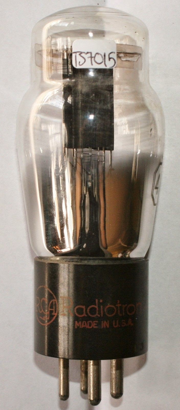
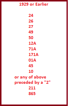
Tubes commonly found in BK transmitters are the type 10, 210, 45, 245, 27 and the 227. All of these types are still available today with some being more costly than others.
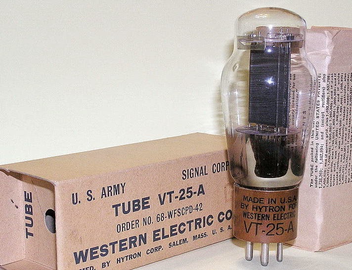 The most common tube is the type 10 or 210 which is also available in a military format, still NIB, as the VT-25. This is the same tube used in the WØVLZ transmitter.
This tube can easily handle the 10W power requirements imposed by the BK and then some.
Typical prices range from $50 and up.
The next most popular is the 45 or 245, which is pretty well maxed-out at around 5-7 watts. The cost of a 45 is about half that of a VT-25.
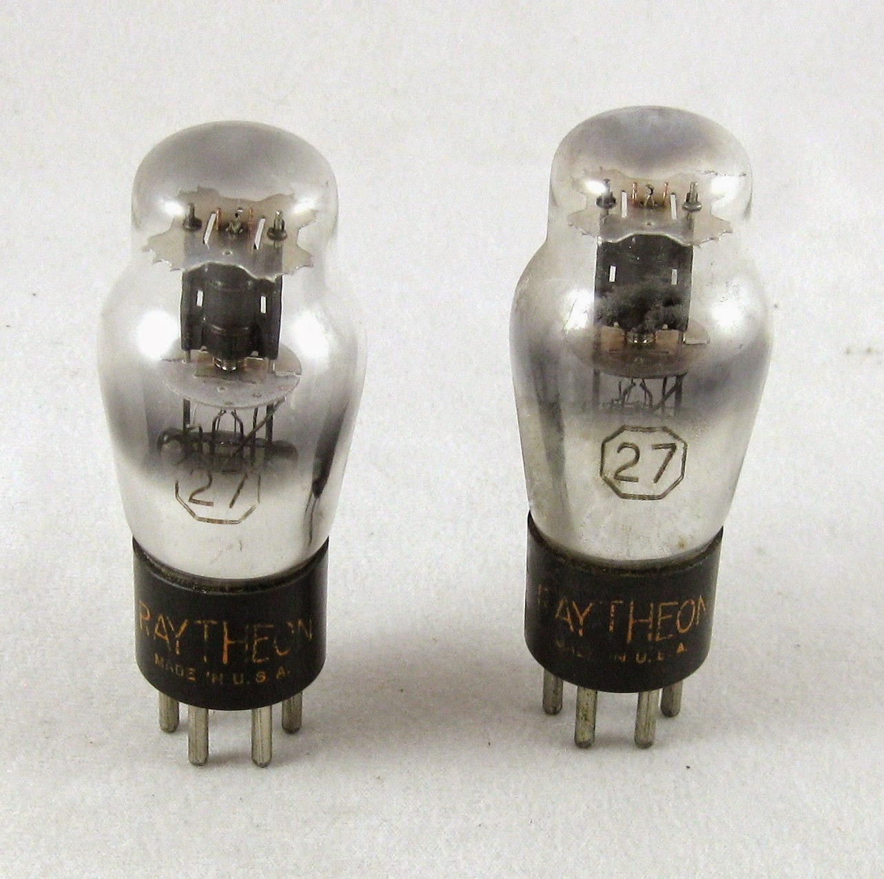
The widely available and inexpensive 27 / 227 will produce 2-3 watts of output...more than enough to work across the continent under normal conditions. The low cost (around $5) makes these particularly attractive for the first-time builder as a transmitter using a pair of these (or more) in parallel is an easy way to get started.
Here is a list of popular tubes that could be used for BK-eligible '29-style transmitters. There are probably more but these are the ones seen most often:
Suitable tubes are always available on e-Bay and from dedicated online tube-sellers. A quick Google-search will turn up several sellers, with prices and condition. Of course, one of the first places to look should be any of your ham friends with deep junk-boxes, especially those that have been building or amassing parts for many years. Check out the next ham fleamarket...especially those dusty old boxes under the seller's table. And...there are probably several hundreds of basements still filled with suitable old parts, just waiting to be liberated....seeking them out is all part of the '29 building fun.
Once a decision has been made to go forward with a '29 project, the first thing is to decide on the type of transmitter to build. There were three popular designs back in the late 20's, each with their own pro's and con's. I'll tell you more about these next and give you a few suggestions for getting started.
In the meantime, see what your 'oldest' ham acquaintance might have in his basement and keep an eye-out for any ARRL Handbooks from the early 30's as they are full of valuable building ideas....and you may wish to check-out K7JPD's ideas for finding old parts.


