 |
 ’29 Style Transmitters…What To Build? – Part 1
 Most hams in the late 20's and early 30's seemed to be using simple transmitters...one or two tubes at the most. No doubt the poor economics of the time made it difficult to build anything really elaborate but it didn't seem to stop them from getting on the air with whatever they could put together.
New rules for amateur radio signal stability came into effect in 1929, making that a pivotal year for amateurs, resulting in several new ideas for 'modern' transmitters hitting the publications of the day.
All of the simpler, one-tube transmitters, were self-excited oscillators capable of pretty good sounding signals when operated correctly and when the wind wasn't blowing the antenna around. Being directly-coupled to the antenna meant that any variations in antenna impedance caused by antenna wire movements, would result in the note rising or falling in frequency by several hertz with the resultant 'musical-sounding' note. You can usually hear lots of these during the windy winter BK Party!
From what I can determine, the most popular first-time transmitter was the one-tube TNT (Tuned-Not-Tuned) style as it could usually be built with parts stripped from an old broadcast receiver.

With a low parts-count, it was easy on the pocketbook. The grid coil was broadly resonant near the plate circuits frequency, resulting in enough feedback to sustain oscillation. The grid coil really needs to be optimised (a simple procedure) for peak efficiency and note quality. You can listen to the note quality on my own TNT while transmitting on 40m.
The Hartley oscillator is just as easy on the pocketbook as the TNT, and in the opinion of most, capable of an even better-sounding note once properly optimized.
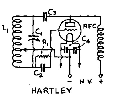
This transmitter is optimized for best note-quality and plate efficiency by finding the correct tap point on L1. Hear my own Hartley's tone while transmitting on 160m.
The third common transmitter of the early 30's was the TPTG (Tuned-Plate-Tuned-Grid).

The TPTG style is a step-up from the TNT and similar in design. Although the added expense of a second variable capacitor made it less popular than the previous two styles, optimizing performance was somewhat easier since the grid circuit could be more readily adjusted for the oscillator's 'sweet-spot' without having to add or remove turns on the grid coil.
All of the triodes mentioned in my previous blog will work well in the above circuits. Keying is normally accomplished as shown below, by connecting the balanced filament resistor on the directly-heated cathode to ground.

It is important to know that construction need not be fancy to get on-the-air for the BK and there is no reason why modern components cannot be used, along with the era-appropriate tube. If you're still undecided, I'll give you some building details to consider next.
Please support our generous sponsors who make AmateurRadio.com possible:
 Ham Radio Deluxe |
 W5SWL Electronics |
 Ham Radio Prep |
 KB3IFH QSL Cards  Hip Ham Shirts  HamRadioAuctions HamRadioAuctions Reliance Antennas Reliance Antennas Enigma Shop Enigma Shop |  morseDX  Ni4L Antennas  R&L Electronics R&L Electronics antennas.us antennas.us QRV QRV |
- Matt W1MST, Managing Editor
