Posts Tagged ‘workbench’
 Solder On, Garth…
While I would love to think that in Wayne’s World, this article would be “excellent,” that’s for you to decide! In this month’s Practical Wireless magazine, my article, “Need a Hand? Or Six?,” is on the cover. Like many hams, soldering work on the bench takes many forms. A lot of that involves setup time to get the right tools in place to begin. I really like to minimize these things so that my limited time is spent goofing up a solder joint..uh, making good soldering joints…and getting things done.
I also have been immensely dissatisfied with the cheap “helping hands” devices found at every hamfest or rally I’ve attended. The magnifying glass tips over too easily, there’s really not enough “hands” to suit me, and if I drop it on my garage floor, it’s likely to shatter. So I was inspired by a previous article in the April 2021 PW about the fabrication of a jig to do SMD work by Michael Jones GW7BBY.
My “artisan” soldering platform is my current solution to having a rather full-featured 12″ square platform with numerous “hands” to hold parts for using my two hands for holding the soldering iron or gun and the solder thread. It’s an honor to publish in Practical Wireless, smartly edited by a world-class contest operator, Don Field G3XTT. His book on 6 meter operation was recently revised and it’s well worth reading before practicing the “magic” in the 50 mhz region!

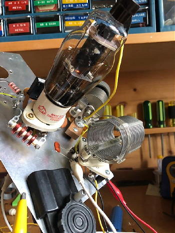
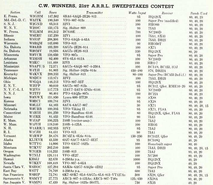
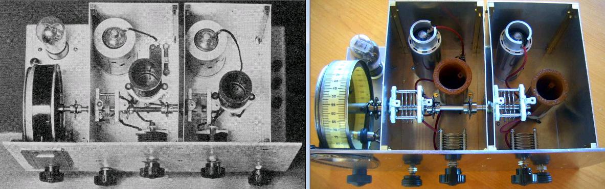
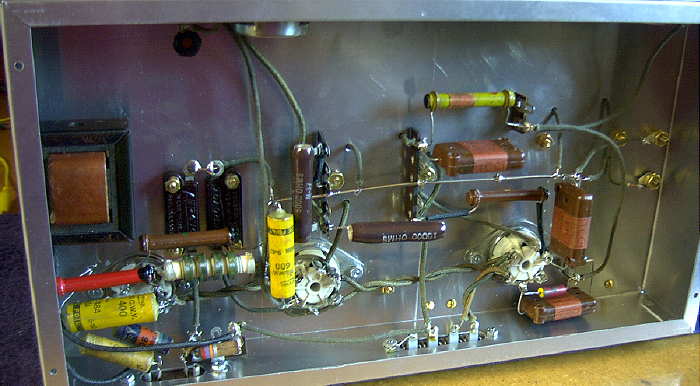
Building A Jones Push-Pull Oscillator
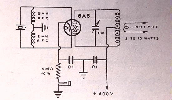
Just as my shelf space for new projects keeps expanding (and quickly running out!), so does my main web site, "The VE7SL Radio Notebook". I have just added a new page to the site describing the construction of my newly-completed Jones Power-Oscillator using a pair of 6L6s.
If you might be thinking of building a 'Jones', you may find something helpful or perhaps find inspiration for a new project. The new page may be found here.
I'm presently building the final version of my RK-39 crystal power-oscillator ... but I have no idea where I 'll put it when finished!
Mr. Carlson’s Lab – A YouTube Treasure
I recently watched two superb YouTube videos. The first described exactly how to determine the 'shielded' side of a fixed capacitor and the importance of knowing this information.
As you have probably noticed, most modern fixed capacitors no longer indicate the 'grounded' end or the lead going to the internal shielding. At one time, the capacitor's polarity was commonly marked with a band on one end but this is no longer the case ... even though one side is indeed still the shielded side. Depending on exactly what part of the circuit your fixed capacitor is being used in, connecting it in the reverse direction (shield going to signal side), can introduce hum, RF pickup, instability and generally result in poorer capacitor / circuit performance ... and all it takes to determine which lead is which is an oscilloscope!
The second video I viewed shows the process used to resurrect a Yaesu FT-1000MP in truly terrible condition. In a very professional step-by-step process the video shows the logical and systematic approach at making the radio better than new.
Both videos are done by a truly gifted engineer, Paul Carlson, VE7ZWZ, and are exceptionally well done ... the quality one would expect to have to pay for rather than freely view on YouTube.
If you visit Paul's YouTube channel, you'll find a host of other radio and audio-related videos and I guarantee that you will learn something of value ... and probably hang around to watch several more. They are really well done.
Drake 2NT And The Novice Rig Roundup (NRR)
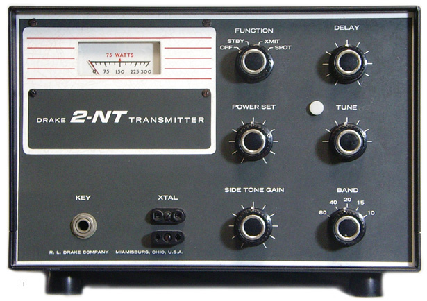
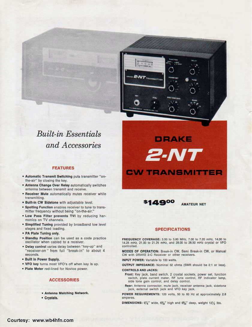
One of this summer's radio workbench projects was to refurbish my Drake 2NT transmitter for this winter's NRR event. The 2NT was introduced in 1966 with the 'novice' ticket-holder in mind, selling for $129. It was the first and only CW-only transmitter produced by R.L. Drake.
As novice transmitters go, the 2NT was a cut above some of the others out there, boasting interesting features such as a built-in antenna changeover relay, sidetone oscillator, grid-block keying and built-in low pass filter.
The tune-up procedure was simplified as well and with Drake's reputation for quality construction, the 2NT became a popular choice for Novices and Generals alike.
My own 2NT was purchased, along with the matching 2C receiver and speaker/Q-multiplier combo over 25 years ago at a Washington state ham fleamarket. Ever since then they have been patiently sitting on the shelf, trying to catch my attention.
The motivation and much-deserved attention finally arrived this year after enjoying last winter's NRR and hearing several great-sounding 2NT's on 80, 40 and 15m CW. I operated the week-long Roundup with my homebrew 'Longfeller' at 5W output, in order to qualify for the QRP category.
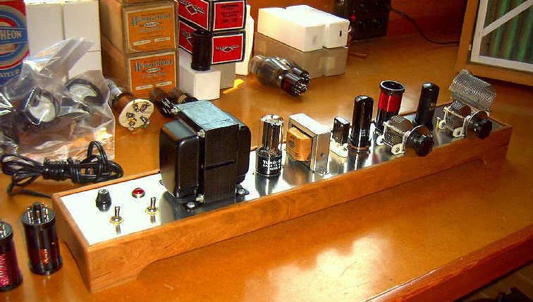 |
| 6AG7 - 6V6 'Longfeller' |
I eventually ended up with 68 contacts, but at 5W, it was a challenge ... most of my many 'CQ NRR' offerings were unanswered, so it was mostly a 'search and pounce' operation. With this in mind, I soon decided that next time, I'll get the 2NT ready to go and hopefully, with a little more oomph, can attract some callers.
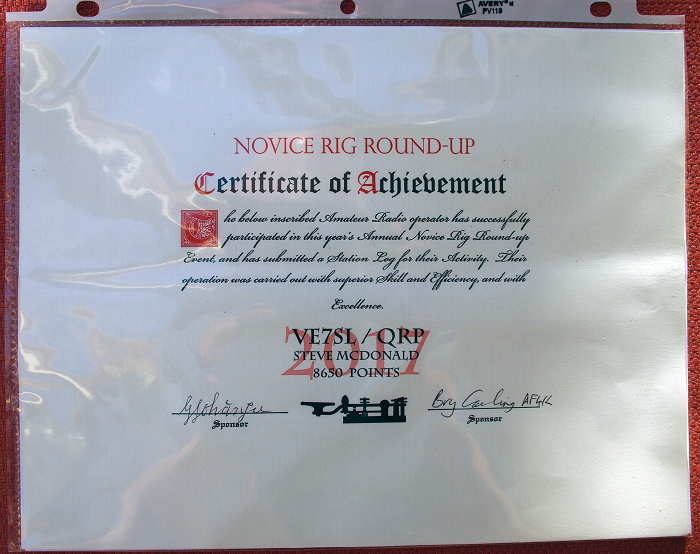 |
| Each entrant received an NRR certificate - a nice touch |
Rather than hunt down and purchase the individual replacement electrolytics, especially the multi-unit can capacitor which was impossible to source, I ordered the '2NT re-cap kit' from Hayseed Electronics. They supply replacement kits for several boatanchors and are able to make and stuff multi-section can capacitors to match the original size and specs ... and all at affordable prices.
After cleaning the chassis and all of the switches, re-tubing with new tubes and removing / replacing all of the electrolytics, the 2NT was ready to go. Using a crystal for excitation, the following results were obtained:
80m 103W input 75W output efficiency = 73%
40m 92W input 65W output efficiency = 71%
20m 92W input 65W output efficiency = 71%
15m 92W input 55W output efficiency = 58%
10m 92W input 50W output efficiency = 54%
Keydown voltages averaged ~520V while plate current ranged from 170-200ma. All-in-all, right on target and not bad for a 51 year old transmitter!
The 6EA8 modified Pierce oscillator in the 2NT seems particularly 'crystal-friendly', as every old style FT-243 style crystal that I tried sounded great. Even the newer ones from AF4K using a modern HC-49 crystal slab mounted inside a vintage FT-243 holder sounded great and worked perfectly.
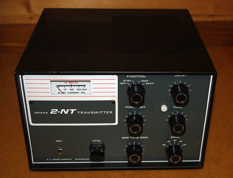 |
| My newly refurbished 2NT - ready to go |
A couple of days later, I returned to the bench to take some blog photos of the rig delivering power into the wattmeter. When I turned the 'stby' switch to 'transmit', the plate current suddenly shot up (with no keying) and the meter on my Variac supply indicated over an amp being drawn by the power transformer ... all with zero output and no crystal plugged-in!
A look at the schematic diagram revealed that with the grid-block keying system, the final amplifier's cathode is always grounded and a low voltage negative bias applied to the grid keeps the plate current cut-off until being keyed ... with cut-off bias missing, plate current will soar, along with transformer primary current. I suspected that something had gone haywire with the bias supply.
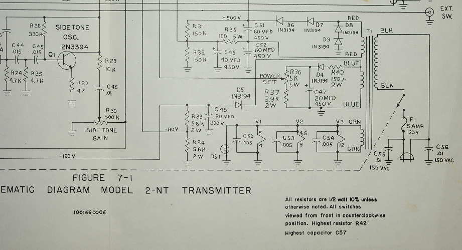
A quick check of the 2NT's printed circuit board containing the bias system components among others, indicated a discolored silicon rectifier (D5) in the bias supply. An in-circuit measurement revealed that it was indeed shorted, basically supplying raw AC across the filter capacitor and shorting out the transformer winding, quickly elevating the transformer's temperature in the bargain ... not good.
Although the diode only has to handle a small amount of current, it was mounted with a heat-producing 2W resistor straddling its top surface. As well, the phenolic circuit board was noticeably discoloured from the heat. I suspect this was the main reason that D5 eventually failed.
My 2NT was an early one, serial #670, so perhaps this parts-arrangement was re-engineered in later models. Once the diode was replaced with a much smaller modern one, of twice the rating, everything returned to normal. The last thing I would want to do at this stage is to burn out the transmitter's unique power transformer, undoubtedly impossible to replace nowadays.
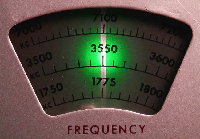
The next bench project will be to refurbish and improve the stability of my Heathkit VF-1 VFO and to mate it with the 2NT.
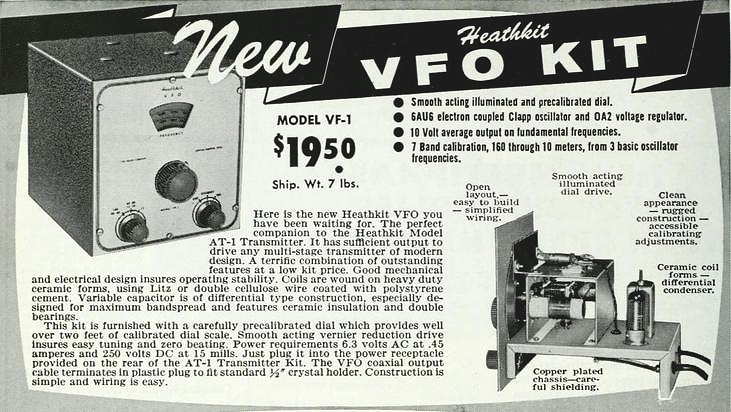 |
| '55 QST VF-1 ad |
Another small quirk noticed on my 2NT is the meter mount. My early model has the meter mounted so low that the silk-screened 'PLATE CURRENT MA.' label is not clearly visible when looking straight-on.
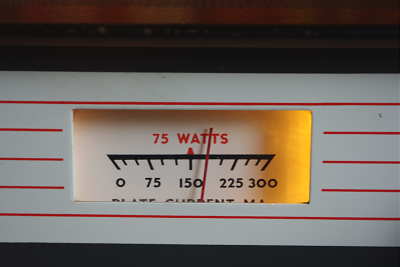 |
| My #670 |
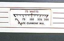 |
| Later models |
You can read many interesting soapbox comments and see some nice NRR station photos from the previous two events here and here, but read with caution as you could easily get hooked. I find pages like this very inspiring and they remind me of the days when QST would publish photos, soapbox comments and exacting equipment descriptions used by each section winner in the annual November Sweepstakes contest.
 |
| Winner's gear in '55 CW SS - remember these? |
VE3AB Netty Electronics
 While ordering components for my 630m transverter project, an internet search for some needed FT-37-77 cores brought me to the website run by Earl, VE3AB in NE Ontario.
Purchasing just a small number of parts can usually be expensive, considering the high cost of mailing these days but in this case, the toroids and a few other parts turned into a real bargain. Earl is a retired Defence Department Manager and Technical Specialist and has one of the most colorful and informative sites that I've ever run across. The extensive, somewhat 'eclectic' site, might at first appear to be a bit disorganized but it really all works nicely once you delve a little deeper ... and there are many layers on Earl's site. It really is quite different and one thing that comes through is his passion for doing things the right way!

It seems that Earl's two main passions are fishing and supplying quality components at good prices. His dirt-cheap shipping to both Canada and the U.S. is something not often seen any longer, as shipping costs often make small purchases totally uneconomical. Forgive me if this sounds like a blatant plug for Earl's business ... it is not. It's just that I found his site extremely interesting and very different from most ... the fact that he is offering something that many hams might find helpful, is my main motivation.
The introductory 'ham radio' page contains, among other things, a collection of Earl's articles describing repairs on many solid state transceivers while his 'Netty Electronics' page describes his small home-based component selling and acquisition activities. His 'ham electronics magazine' page contains articles on working with circuit boards (re-capping, repairing, de-soldering), antenna articles as well as numerous articles on components, all authored by VE3AB. Earl's website and free services are all financed by personally using monies obtained through sales of parts and part radios as he sees it is a service to the amateur radio hobby, which he obviously loves deeply.
Earl specializes in solid state devices of all description, from vintage to modern. He offers a vast selection of parts for older radios and has information on repairing dozens of older solid state rigs. All parts are tested or guaranteed to be working within specs.

His pages contain extensive information describing his tests of popular Chinese-made transistors, such as this one describing a batch of dual-gate MOSFET BF981 transistors. His 'test' pages are definitely worthy of your attention and, for many, might be a bit of an eye-opener.

If you are looking for a manual for an older rig, Earl has an extensive offering of free manuals on his site. If it's not there, he can probably get it for you.
He is continually buying up collections of older components, as well as new parts ... if you have stuff to unload you might wish to check with him as so many of these valuable parts end up in the trash as shacks go silent. His extensive list of components can be found here. ... you may just find that special part you've been looking for.
One of Earl's goals for the website is to put up a search-engine for his parts but in the meantime, I found my browser's "Find" function worked well in sorting through the large list.
There is enough interesting information on his pages to keep you reading for hours and I find the random nature of much of it rather attractive. Earl says that changes to the site are coming but I hope they're not too drastic ... I kind of like it just the way it is!
1933 Regen Project
 Monday was spent finishing the coil winding for my present bench project, a 3-tube regenerative receiver. The receiver first appeared in the January '33 QST article, "Rationalizing The Autodyne", by George Grammer. I tried to stay true to the original design, both physically and electrically, as much as possible. Where period components were not available, they were manufactured. Several capacitor are 're-stuffed' cases and some resistors have been physically altered to resemble era-appropriate styles. The one deviation I made from the original circuit was to remove the B+ (200VDC) from the headphones by going to impedance-coupled audio, which blocks DC from the headphone circuit. After finishing the coils and doing a quick re-check of the wiring, I held my breath and applied the power.
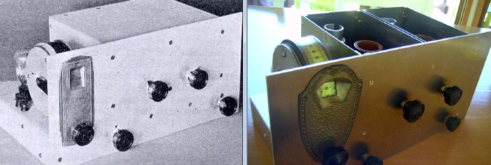
Much to my surprise and delight, the receiver worked immediately. It took me some time to find the correct control settings and combinations that seemed best but eventually its operation became familiar. Here are a couple of short recordings, crudely made via connecting the computer across the high-impedance headphones, as I tuned across a somewhat noisy 40m band in the evening.

Now although the receiver appears to be working, I'm not 100% convinced that it is working as well as it should. It's difficult to know exactly how it should perform when at its best as it really can't be compared to any of our modern-day receiving systems. Just what did 'good performance' sound like in 1933?
I have some reservations about one of my tubes. It's a '78' from my junk-box stash and has a large red '?' inked across the glass envelope. I may order some NOS '78's or even some more modern '6D6's, to see how they perform. On the plus side, the oscillator seems very stable and there is absolutely no 'hand-effect' on tuning, a common problem with many regens. Peaking up the RF stage tuning causes no pulling of the oscillator but the '78', although a hot-performer in 1933, provides plenty of tube noise as well, if the gain is set too high. I think the main advantage of having the tuned RF stage is to add RF selectivity and eliminate any bleed-through from some of the blowtorch shortwave signals just up the band. Tuning seems best when its gain is set between fifty and seventy-five percent of maximum. The large drum dial, in combination with the small bandspread capacitor, spreads 40m across most of the dial and makes for easy tuning although there is a small amount of backlash.
Another thing I noticed is that it seems to be very receptive to spurious computer birdies, with the laptop sitting just a foot away. Perhaps its unshielded top and bottom are the cause of this as I don't hear any of the signals on my main station receiver.
Comparing it to the two-tube regen in my Paraset, the Paraset sounds much quieter and generally sounds more sensitive ... but it uses more modern tubes, '6SK7's, first introduced in 1938, five years after the '78'. The selectivity seems as good, if not better, than the Paraset, which I consider an excellent performer. The Paraset also sounds just as good as my National SW-3, which was produced in the early 30's ... so the new regen is likely not as quiet nor as sensitive as the SW-3, probably the best simple regen of its day.
Perhaps some newer tubes will make a difference in performance and maybe my expectations are too high. In any event, the closing paragraph of Grammer's article may be more telling that I originally thought:
"The set as it stands is not perfect, of course; nothing ever is."
Crystals Go To War
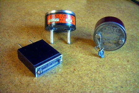
Thanks to a recent posting in the Yahoo ParasetBuilders Group, I have a new-found respect for my small collection of prewar crystals! If you've ever wondered how a rough chunk of quartz gets transformed into an accurate frequency-generating device, this 'cinema-style' documentary shows exactly how it was done ... truly an amazingly complex, yet delicate, labor-intensive process.
After viewing the documentary, I can't help but wonder what later health effects some of these workers may have undergone after seeing them handling some nasty-looking chemicals and working directly beside desktop X-ray machines. If you've used old WW2 crystals before, I think you'll enjoy seeing how much work went into their production.


