Posts Tagged ‘vhf/uhf’
 The best of the Baofeng handhelds
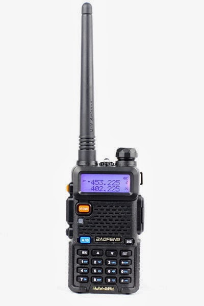
How do the cheap Baofeng handhelds compare? I have had the Baofeng UV-5R since I bought it from the 409shop in April 2012, but recently I noticed that the UV-B5, UV-B6, and UV-82 have appeared on the market also. If I should need another handheld transceiver for VHF/UHF, is there any advantage in getting any of the other models?
I prepared the following table in order to highlight differences and similarities. Bold characters signify an improvement for what I conceive to be typical radio amateur use.
Feature | 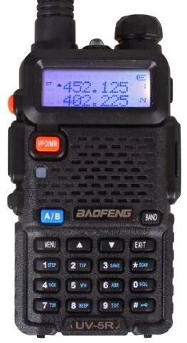 UV-5R |  UV-82 | 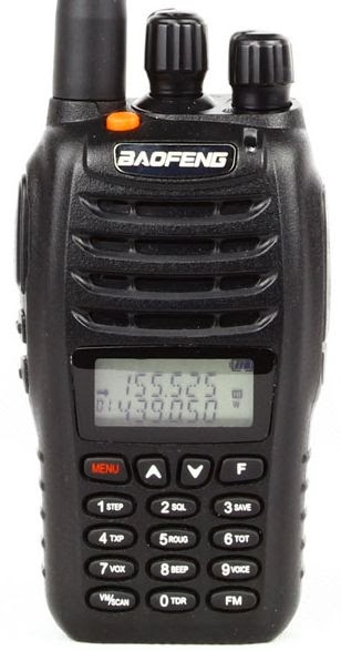 UV-B5 |
|---|---|---|---|
| Front-end | OK | OK | Improved |
| Antenna | Short | Longer | Longer |
| Signal meter | On/off | On/off | Dynamic |
| Squelch | VHF: On/off UHF: Tiny steps 21. Dec 2013 | As the UV-5R 21. Dec 2013 | Larger steps |
| Size and shape | Square and small | Fits better in hand, larger buttons | Fits better in hand |
| Frequency/channel change | Up/down | Up/down | Rotary encoder |
| VFO/MR button | Yes | Turn radio off, then press menu as you turn it on 3. Jan 2014 | Yes |
| Band button | Yes | No (in menu) | Switches automatically |
| Dual PTT button | No | Yes | No |
| Programming | Need a computer to enter alpha tags | Alpha tags can be entered from keyboard | Alpha tags can be entered from keyboard |
| Memory channels | 128 | 128 | 99 + 16 for FM radio |
| Display | 7 characters in name | 7 characters in name | Harder to read, only 5 characters in name |
| Modifications | Enlarge mic hole, (and here), Low modulation mod | – | Unused button as background light switch |
My main sources are the blogs of PD0AC (UV-82, UV-B5/B6) and the Miklor FAQs
In general I think the design of much radio equipment is lagging behind other electronics when it comes to user interfaces. Imagine a smart phone user interface on a handheld! That is why I emphasize user interface issues in my final evaluation.
I like the improved front-end, signal meter, and squelch of the UV-B5 making it a strong contender for the winner position. But I don’t think they are worth the price of a poorer display. On the other hand, the UV-82 is inferior in my view to the UV-5R due to the need to enter the menu for VFO/MR and band switch functions. So for now I’ll stick with the UV-5R.
How To Do a SOTA Activation On Pikes Peak
This post was updated on June 4, 2022, after the summit house construction was completed.
Perhaps this should be called The Slacker’s Guide to Activating Pikes Peak since I am going to describe the easy way to do a Summits On The Air (SOTA) activation on America’s Mountain. If you plan to hike up, you have my complete support but this post is not meant for you.

Pikes Peak (W0C/FR-004) is about 10 miles straight west of downtown Colorado Springs. See the Pikes Peak website for useful tourist information. At an elevation of 14,115 feet, the mountain towers over Colorado Springs and the other front-range cities. (You may see the elevation listed as 14,110 but it was revised upward in 2002 by the USGS.) This means that it has an excellent radio horizon to large populated areas. On VHF, it is possible to work stations in Kansas, Nebraska, Wyoming and New Mexico. See VHF Distance From Pikes Peak and Pikes Peak to Mt Sneffels. On HF, you’ll do even better.

Getting There
Access to the summit has three options: hike up, drive up via the Pikes Peak Highway or ride the Pikes Peak Cog Railway. Most people will probably choose the highway since the cog rail only gives you 30 to 40 minutes on the summit. (Normally, you return on the same train that takes you to the top. You can try to schedule two one-way trips but that is a challenge.)
After a few years of turmoil and construction, the summit of Pikes Peak is now back to operating normally but with some changes. The new summit house/visitors center is open and it is a beautiful new facility. The Cog Railway is also operational with brand new equipment. There is a new boardwalk that allows easy strolling on the summit and improved views near the edge of the summit.
Pikes Peak Highway
The highway is at a well-marked exit off Highway 24, west of Colorado Springs. There is a “toll” to use the highway (~$15 per person, check the Pikes Peak Highway website for the latest information and a $2 discount coupon.) Starting in 2022, you must have a reservation (2-hour window) to drive to the summit (roughly Memorial Day to Labor Day). The specifics are likely to change, so be sure to check the Drive Pikes Peak page for the latest updates.
The road is paved all of the way to the top and is usually in good shape. The only caution on driving up is that some people get freaked out by sections of the road that have steep drop-offs without guard rails. It is very safe, but some folks can’t handle it. The main caution driving down is to use low gear and stay off your brakes. There are plenty of signs reminding you to do this and during the summer there is a brake check station at Glen Cove where the rangers check the temperature of your brakes.
It takes about an hour to drive to the summit, assuming you don’t dawdle. It is best to drive up during the morning and avoid the afternoon thunderstorms.
On The Summit
The W0C Association Reference Manual (the SOTA rules for Colorado) used to suggest a “qualifying hike” of 100 vertical feet but this item has been removed from the manual. If you decide to do such a hike, I suggest you proceed down Barr Trail which is the main hiking trail coming up from the east side of the peak. Do not try to walk along the road, as the rangers will stop you. The trail starts on the east side of the summit house (towards Colorado Springs) and is marked with a sign. You have to cross over the cog rail tracks to get to it. (Please try to avoid getting run over by the train as it scares the tourists and makes a mess.)
The summit of Pikes is broad, flat and rocky, so pick out a spot away from the buildings for your SOTA adventure. There are quite a few radio transmitters on the peak so expect some interference. Since this is way above treeline, your antennas will have to be self-supporting. For VHF, giving a call on 146.52 MHz FM will usually get you a few contacts and sometimes a bit of a pileup. Be aware that on top of Pikes you are hearing everyone but they can’t always hear each other. It can get confusing. Another VHF simplex frequency worth trying is 146.58 MHz (The North America Adventure Frequency). On the HF bands, pray for good ionospheric conditions and do your normal SOTA thing.
Your body and your brain will likely be moving a little slower at 14,000 feet due to the lack of oxygen. Don’t be surprised if you have trouble deciphering and logging callsigns. Take it slow and monitor your physical condition on the peak.
Bring warm, layered clothes, even in the summer, since Pikes Peak can have arctic conditions any time of the year. Keep a close eye on the weather since thunderstorms are quite common during the summer months. Lightning is a very real danger, so abandon the peak before the storms arrive.
73, Bob K0NR
Resources
SOTAwatch web site
W0C SOTA Website
Pikes Peak Tourist Information
Pikes Peak (W0C/FR-004) SOTA Page
Pikes Peak Webcams
The post How To Do a SOTA Activation On Pikes Peak appeared first on The KØNR Radio Site.
GSM phone power control and signalling
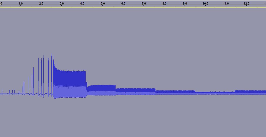
When you measure the energy out of a GSM cell phone at the moment of initiating a call, you get the picture to the right. It shows the first 15 seconds.
For the first 3.5 seconds there is the signalling between the phone and the base station. Then the connection is established, but after some time (at 4.2, 5.6, 7.5 and 9.5 seconds) one can see how the phone turns the power down, according to the commands it gets from the base station.
 The first example was for the case of a strong received signal, all bars are shown in the signal strength meter. The reduction in power, preservers battery life and as a side effect the user is exposed to a smaller amount of radiation. Interestingly, one can see that after a while there is a small adjustment of the power and it is turned up a bit (at 11.5 seconds).
 In other cases one can see a situation which follows the same pattern in time, except that the power stays at a high value. This second recording was done in my basement where GSM coverage is much poorer. Here the phone’s signal level indicator hardly shows any signal.
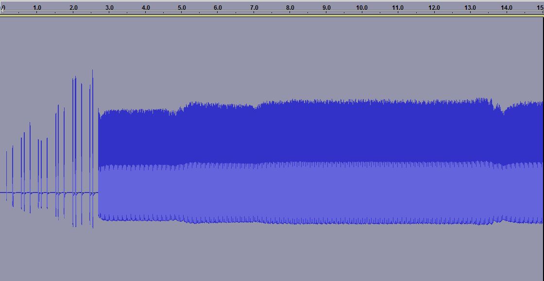

The third plot is a zoom of the previous one. Here one can see how the phone only transmits 1/8 of the time as it shares the channel with 7 other phones in a time multiplex. It is allowed to transmit every 4.6 ms and this is the reason why one often can hear a buzzing sound at 1/4.6 ms = 217 Hz in equipment which is placed close to a phone.
One also sees another frame structure, as the phone transmits 25 bursts and then breaks for one burst before continuing. Every transmission consists of 150 bits, but that is not possible to resolve with the simple setup that was used here.
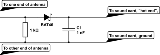
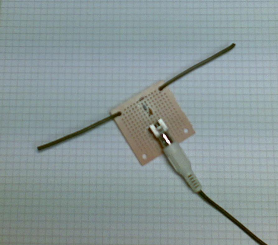 The equipment was a dipole antenna and a simple diode detector:
- A half wave dipole antenna for 950 MHz has a length of 0.5*3*108/950*106 = 15.8 cm, thus the antenna is about 2 x 8 cm (probably not very critical). The antenna was made from stiff self-supported wires.
- There is a resistor of R=1 kohm across the antenna and then a Shottky diode which acts as a detector (A Shottky diode which handles higher than 1 GHz is needed and BAT46 was used here), and finally a 1000 pF capacitor as a filter.
This post was inspired by William Andrew Steer’s “GSM phone signal analysis“.
Half a year of APRS temperature monitoring
 My APRS-based temperature monitor has now worked flawlessly for half a year. APRS stands for Automatic Packet Reporting System so it can send much more than temperature data, the chief usage is really for GPS position reports.
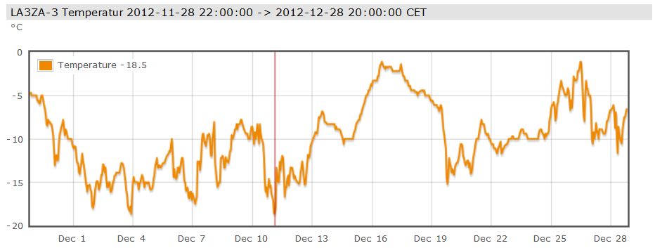
But I just needed a temperature monitor and here are the readings for December. As one can see, there were no days with temperature above freezing. At 800 m elevation in the mountains of Telemark in Norway, this is not unexpected for this time of year and makes for good skiing!
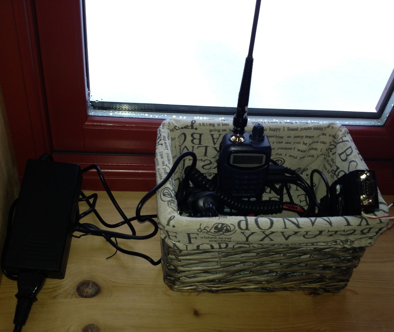
I use a Quanzheng TG-25AT handheld with a quarter-wave whip antenna on 144.800 MHz. Its signals reach the LD3GT digipeater at 1845 m above sea level. Although I don’t have direct line of sight, the low power (1 Watt) setting is adequate as the distance is only 10 km. The APRS-beacon is an OpenTracker USB set up for transmission every 15 minutes. An external DS18S20 temperature sensor which measures the outside temperature is connected to the 1-Wire® bus of the OpenTracker USB.
Thanks to the infrastructure providers: The Tønsberg group of NRRL (LA1T) who operate the LD3GT digipeater, probably the one with the largest coverage in Southern Norway (Gaustadtoppen). Thanks also to the various operators who receive packets from LD3GT and pass them on to the internet, and thanks to aprs.fi for processing and displaying the data on their excellent web site!
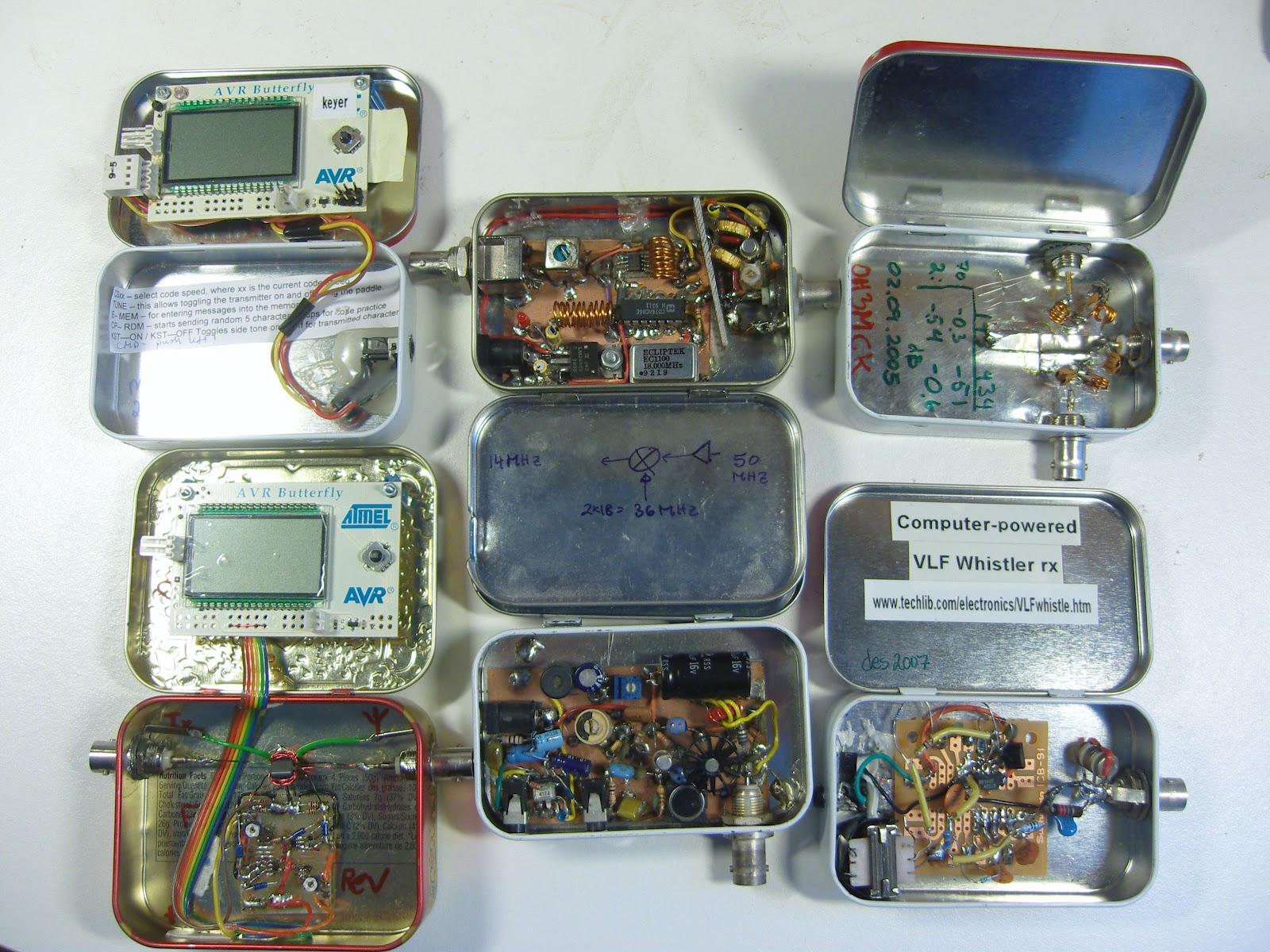
Altoids Projects
 |
| Press image for magnification |
I like to build small electronics projects and like many others I have found the small Altoids tins to be excellent enclosures.
These tins are inexpensive, well shielded, easy to work with, and least but not least they enable you to make experimental circuits that are sturdy enough that they can be reused later.
Pictured here is a collection of projects I have built over the years with the hope that they may inspire others.
To the left:
- AVR Butterfly morse keyer (KD1JV)
- AVR Butterfly Digital SWR / Power Meter for low power transmitters (KD1JV). Actually this project was built in the slightly larger Whitman’s tin.
In the middle:
- 50 MHz to 14 MHz receive converter (WA3ENK) with a low-noise preamplifier
- Pixie II QRPP transceiver for 30 m
To the right:
 |
| Press image for magnification |
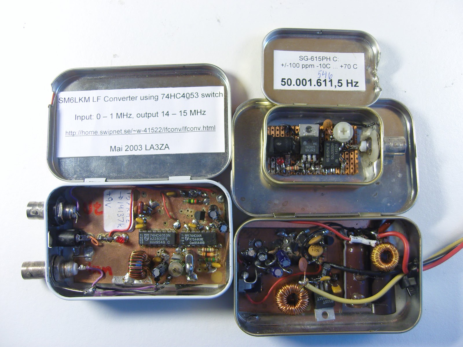
In the next picture there are some more projects:
- SM6LKM’s 4053 HCMOS converter from 137 kHz to 20 meter band.
- A 50 MHz test oscillator for testing 6 m receivers
- A switch mode power supply that converts 15 Volts into 4.5 and 30 Volts for a WWII miniature Sweetheartshortwave receiver. Design inspired by SM0VPO/G4VVJ’s practical voltage converter.
Here are some resources with tips:
- Maxim Tutorial 946: Disposable Metal Boxes Make Excellent Shielded Enclosures (via Dangerous Prototypes)
- Getting Started – Top 10 Small and Fun Electronics Projects – DIY Electronics
- Curiously Hackable: 8 Awesome Altoids Tin Hacks
- Altoids tin prototyping board (Make blog)
Added 17. September: Several of the comments on the page at Dangerous Prototypes are concerned with the difficulty of finding Altoids tins in many places of the world. That goes for Norway also. I have been lucky enough to have a job that allows me to travel to the US from time to time and then I have bought some. Ideas for local alternatives are needed!
Foxhunt gear – offset attenuators
I attended a great fox hunting presentation at Dayton this year, hence a few posts on the topic.
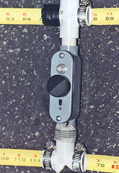
I had some posts in the past about tape measure beam antennas. Really neat antennas and they have multiple purpose use (they are GREAT for hitting distant repeaters when you orient them vertically!). Much like the picture on the right (courtesy of Joe Moell K0OV) they are more useful for fox hunting when you add the active attenuator to your setup. FYI, Joe is the co-author of the great book “TRANSMITTER HUNTING, Radio Direction Finding Simplified” available where most ham books are sold. His website has more information on the book at http://www.homingin.com/THRDFSinfo.html and he contributes to CQ and CQ VHF.
So….. just what is an offset attenuator? Joe explains it on his “Homing in” site as:
An RF attenuator is a device that goes between antenna and receiver to reduce the signal strength down to within the range that the receiver S-meter can handle. Without one, you may think you’re close to the fox when you’re still far away. You won’t be able to get close enough to a camouflaged hidden T to identify it. The amount of attenuation should be adjustable so that you can add just a little when your S-meter first pins, up to a lot as you get within a few feet. Special ARDF receivers used by champion foxhunters have electronic attenuation built in, but ordinary handi-talkies don’t. Adding it would require major micro-surgery in the HT.
His attenuator page is:
http://www.homingin.com/joek0ov/offatten.html
I recommend his site in general, many great projects:
On his attenuator page, he has full schematics to make an offset attenuator.
But wait…… there’s more!
Further on his page, you see one made in a sweet Pomona box.  I like this box and thought it was a bit pricey at first, until I did the math and figured out the cost/time to do it myself. These boxes are shielded with the connector of your choosing (BNC/SMA/259, etc).
They generally cost around $25 or so and are shielded! Great to have. When you add the cost of connectors and such, it isn’t really so expensive after all.
I really advise using such a case or a metal case in general, makes things work out much smoother in the end. More information on this box at: http://www.pomonaelectronics.com/index.php?i=prodsub&parent=BOX&cat=BONCONN&getDetails=
But wait….. there’s even more!
 Marvin Johnston KE6HTS is now offering a “semi-kit” for this attenuator on his website. I’ve seen this kit when I was at Dayton this year and encouraged a friend to pick it up and build. I may end up running a buildathon here in CT on these attenuators.
The price is really not bad at $22.00. You can purchase them built for a few dollars more.
Information on the kits and pre-built models are at:
http://www.west.net/~marvin/k0ov.htm
And yep……. there’s even more (again!).
If you would like to “roll your own” from parts you may have on your bench, but don’t want to make a circuit board, you can get one from……. you guessed it…… Far circuits. I picked one up and am going this route myself.
There are a few boards/projects on the Far circuits website at:
There are a ton of great resources out there on the web, these will really get you going right from the start. Fox hunting is a really fun and useful part of our hobby and one that doesn’t cost a ton of money to get started in. If there are no active fox hunts in your area – start ‘em! There are plenty of options as far as transmitters and such and really doesn’t cost a club much money to get started.
The Montreal Doppler
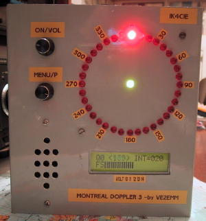 So, here I was at Dayton a few weeks ago and decided to check out the fox hunting/amateur radio direction finding (ARDF) forum. I forgot who did the forum, but it was actually very well done. One of the projects I learned about was “The Montreal Doppler”. This is a really neat project designed by Jacques Brodeur, VE2EMM.
I saw many neat attenuators, offset attenuators….. but this….. well…. it has LEDS! Pretty lights…. OK, I digress. Working with a bunch of these LED’s is pretty kewl and looks sweet. This is a project that is well documented on the web and I’ll provide links below.
The biggest question I had was, where do I get the microcontrollers and firmware. Not only was I able to acquire the PICS (microcontrollers), but I was able to get PC boards and the LCD for a very reasonable price from FAR Circuits! I know I picked up the last one he had at Dayton, but he may be able to do more (they cost $45.00). Check out the FAR circuits website at http://www.farcircuits.net/
A little about this project from VE2EMM’s website, list of features:
– 36 LEDs display; center LED when green = good signal, when red = no signal , the direction is frozen to the last good signal.
– Uses 3 PICs; a PIC16F628A for the display, a PIC18F4520 as the main processor and a PIC12F675 as a frequency divider.
– Filters; a Max 267, the best bandpass filter that I have ever seen, followed by the Roanoke switch cap filter for very narrow band width (+/- 0.5Hz).
– My DopplerII integrating and phase detection software in the main PIC.
– LM386 for monitoring the audio independently from the doppler.
– Simpler menu selection, turning a selection pot and a pushing a DO switch.
– It will switch 4 antennas with a + or – going signal, 4 antennas differential, 8 antennas with a + or – going signal.
– Pushing the DO PB sends the direction to APRS. The protocol is: <cr><lf>%359/Q<cr><lf>. The Q (0<8) is the quality of the signal just before the
extraction of the phase information.
– GPS information goes through the doppler, it will be instantly interrupted when the doppler sends a DF to APRS on a PC.
– Faster main processor, PIC18F4520. **** NEW **** June 06
The model I saw really intrigued me and there are a few really well done websites devoted to this project (it has quite the cult following).
The original site is at:
http://www.qsl.net/ve2emm/pic-projects/doppler3/doppler3-e.html
Here is another page on Jacques site that has some examples from other builders:
http://www.qsl.net/ve2emm/pic-projects/doppler3/md3_photos/dopler%203%20pictures.html
KA7OEI has a neat page with a bunch of information on this project:
He has a lot of information about an alternate firmware that looks like the image below:
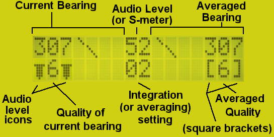
The alternate firmware page is at:
http://ka7oei.com/emm2_mont2a.html
If you have any more information on this project, resources or anything of the sort, please comment below.


