Posts Tagged ‘vhf/uhf’
 Latest firmware for AP510 APRS tracker is superb
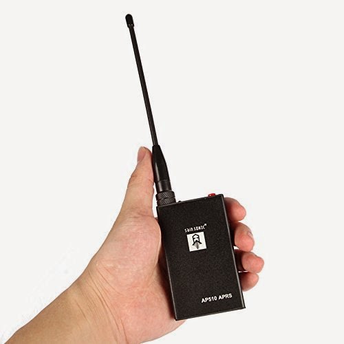
I got my AP510 APRS tracker a little more than a year ago. It kind of worked, but not very well in my car. But after the tracker got a new firmware dated 3 Nov 2015, it has become so much better. Now I can say that it is really useful.
Apparently, the Smartbeacon function didn’t work properly in earlier versions of the firmware. With some good debugging and error reporting by KC5EVE, Mark, working with the software developer for the AP510, BG6QBV, the annoying errors now seem to be gone. This is all documented in the Yahoo AP510 group.
I have fitted mine with a 16-45 cm telescopic antenna and even when attached to one of the rear headrests in my sedan, the 1 Watt of output power tracks very well.
The map below shows a drive from Telemark, about 100 km west of Oslo, to Oslo with as good coverage as one can expect given the valleys and the availability of APRS digipeaters on the way.

Latest firmware for AP510 APRS tracker is superb
I got my AP510 APRS tracker a little more than a year ago. It kind of worked, but not very well in my car. But after the tracker got a new firmware dated 3 Nov 2015, it has become so much better. Now I can say that it is really useful.
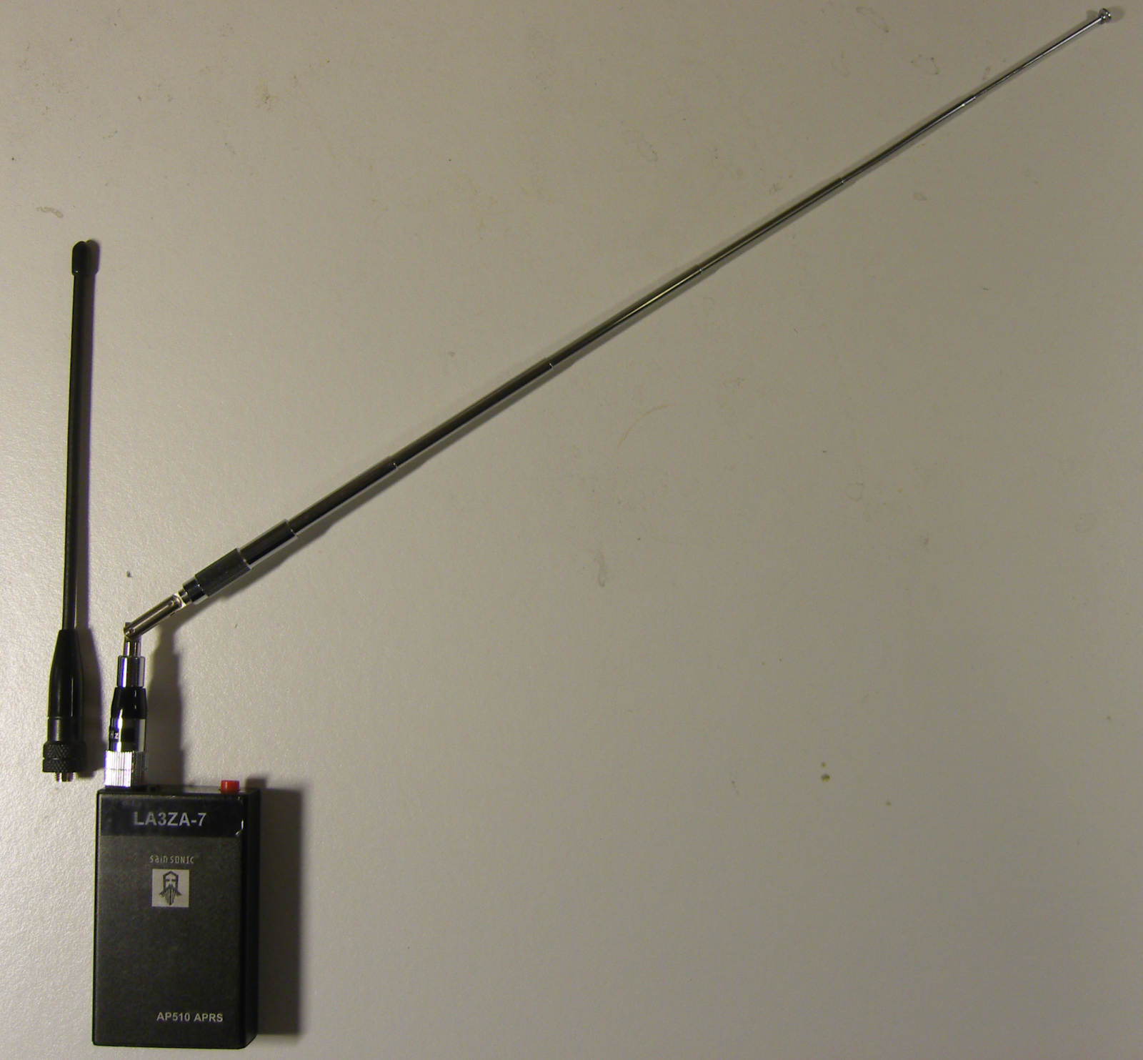 |
| AP510 with original short antenna and telescopic antenna |
Apparently, the Smartbeacon function didn’t work properly in earlier versions of the firmware. With some good debugging and error reporting by KC5EVE, Mark, working with the software developer for the AP510, BG6QBV, the annoying errors now seem to be gone. This is all documented in the Yahoo AP510 group.
I have fitted mine with a 16-45 cm telescopic antenna and even when attached to one of the rear headrests in my sedan, the 1 Watt of output power tracks very well.
The map below shows a drive from Telemark, about 100 km west of Oslo, to Oslo with as good coverage as one can expect given the valleys and the availability of APRS digipeaters especially in the western part.
|
| Note the missing tracks east of LA5PPA-1 which are due to a 3.5 km long tunnel, Strømsåstunnelen, between Drammen and Mjøndalen. |
2014 SET
Worst snow winter since 1958 and an indoor Yagi antenna

Norway has had its fair share of precipitation this winter. Along the coast most of it has been in the form of rain. But that is different in the mountains. Our cabin at 800 m above sea level is now about to disappear in the snow and we can hardly see out of the windows anymore. This is a result of having had to shovel the snow off the roof three times so far this winter. And there is yet more to come.
They say that one has to go back to the winter of 1958 for more snow than we have had this winter, and we are still only in February. The snow has also given us an unexpected problem. Our digital TV signal is now gone. The TV transmitter is at Mount Gaustadtoppen at 1883 m ASL which is about 10 km to the North and with almost free line of sight. It used to be possible to receive the signals from the national TV provider (Riks-TV) with just a simple indoor dipole, i.e. two wires each of length 13-14 cm connected to a coaxial cable. But not so anymore after all the snow has accumulated outside the windows.
Therefore I had to find a good Yagi-antenna calculator and make a better antenna. I put it on a cardboard of length 45 cm and used the antenna calculator of K7MEM (Martin Meserve). It is a little hard to figure out the exact frequency as there are 5 multiplexes in the TV system and for that particular transmitter they range from 506 to 620 MHz (http://www.finnsenderen.no/finnsender). I therefore just designed the antenna for the multiplex in the middle, 563 MHz. The wavelength is 53.3 cm and typical antenna element length is half of that.

The antenna calculator gave me a design with one reflector behind the receiver element, and four directors in front of it. In the picture, the reflector is to the left and the antenna points to the transmitter to the right.
I made the elements from thick wire, and just taped them to the cardboard. The connector to the coaxial cable is under the cardboard and attached to the center of element two from the left – the one which is split into two.
The Yagi antenna was first described by H. Yagi in the paper “Beam Transmission of Ultra Short Waves“, (Proceedings of the Institute of Radio Engineers, 1928). But as the contribution from his colleague Uda was at least as great as Yagi’s, the antenna should really be called the Yagi-Uda antenna. I seem to remember that Uda could not write English (both of them were Japanese), so the article was written in the name of Yagi only.
But what about my Yagi, eh Yagi-Uda antenna, did it work? Yes, actually it did! With digital signals there is a threshold effect and above a certain signal level the signal quality quickly goes to 100% with a low BER (bit error rate) and with this antenna I came above that threshold. The gain of this antenna is in the order of 8 dB or about 6 dB more than the old single element antenna. Luckily, that was enough to compensate for the attenuation through the snow pile. And as you can see, one doesn’t need aluminium to make a working TV antenna.
[In Norwegian: Verste snøvinter i manns minne og en innendørs TV-antenne]
Video of busy 70 cm ISM band due to car key fobs
Data recorded from an RTL-SDR USB dongle with the SDR# program using the Apowersoft Free Online Screen Recorder.
Related posts:
- “Car keys in the 70 cm band” (with more documentation of hardware and software)
- “Not so busy 70 cm ISM band”

Not so busy 70 cm ISM band
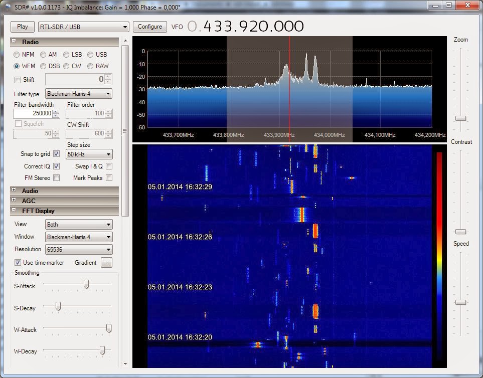
Yesterday’s post entitled “Car keys in the 70 cm band” showed a very busy band around 433.92 MHz with up to 10 simultaneous transmissions. That snapshot was taken on a Sunday afternoon at 16:32 local time. Here is a much less crowded snapshot taken with the USB SDR-RTL dongle under the same conditions as the previous blog post. The difference is that this is from late Monday night at 23:34 local time:
 |
| Press image for a larger view |
Thanks to all viewers who have made the former blog post the most popular on my blog for this week. Thanks also to the RTL-SDR blog which gave it publicity in the blog post “Looking at the 432 to 438 MHz ISM band“.
Related posts:
Car keys in the 70 cm band
 |
| Press image for a larger view |
Related posts:
- “Not so busy 70 cm ISM band” showing the status on a late Monday night
- “Video of busy 70 cm ISM band due to car key fobs“


