Posts Tagged ‘Ultimate 3’
 Comparing two antennas with WSPR
 |
| Ultimate 3S with 5-band relay module in front, variable LM2596 power supply (with voltmeter) for the power amplifier behind left, a variable LM2596 supply set for 5 Volts for the Ultimate 3S in the middle, and the antenna switch to the right in the back. |
WSPR – The system for Weak Signal Propagation Reporter makes it easy to compare antennas if your transmitter can easily switch antennas. The system shown here can send on antenna 1 for almost two minutes and then switch immediately to antenna 2 for the next transmission.
The Ultimate 3S already has software that supports that and application note 3 from QRPLabs (Controlling additional relays using the Ultimate3S “Aux”) describes how. I built mine following that note and the experience from EA1CDV.
The circuit is controlled from pin D7 and consists of a transistor, a relay, a resistor and an electrolytic capacitor. In addition I have two LEDs that indicate which antenna which is in use. In the first picture the green LED in the back right under the BNC antenna connector shows that antenna 1 is connected.
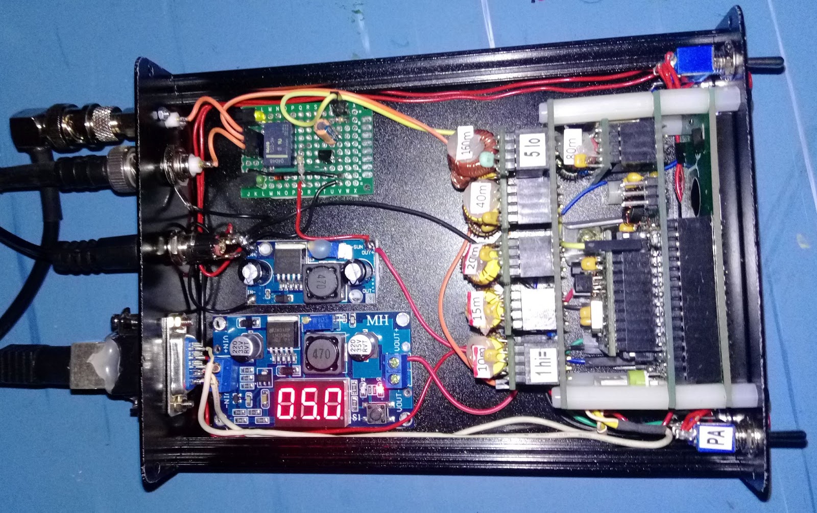
In the next picture, the whole layout is shown a little better. In this case LED 2 is lit, the faint yellow one. It sits right under the additional SMA antenna connector in the top left-hand corner that I had to fit.
I have used this setup for a few days now on 7, 10, 14, and 18 MHz with some crossed doublet antennas (somewhat like this setup, but not in the same location). I change the frequency between antennas, e.g. 50 Hz below the center frequency of the band for antenna 1 and 50 Hz above for antenna 2 in order to simplify discrimination between the transmissions.
The short 13 m antenna transmits best East-West, and the longer 26 m antenna North-South. The directivity is in general confirmed by the WSPR reports I see. Sometimes the difference can be more than 10 dB in SNR, but more often it is closer to 5 dB. But it also happens that only one of the transmissions is detected. This should make for some interesting analysis in the coming months.
The post “Comparing two antennas with WSPR” first appeared on the LA3ZA Radio & Electronics Blog.
Comparing two antennas with WSPR
|
| Ultimate 3S with 5-band relay module in front, variable LM2596 power supply (with voltmeter) for the power amplifier behind left, a variable LM2596 supply set for 5 Volts for the Ultimate 3S in the middle, and the antenna switch to the right in the back. |
WSPR – The system for Weak Signal Propagation Reporter makes it easy to compare antennas if your transmitter can instantly switch antennas. The system shown here can send on antenna 1 for almost two minutes and then switch immediately to antenna 2 for the next transmission.
The Ultimate 3S already has software that supports that and application note 3 from QRPLabs (Controlling additional relays using the Ultimate3S “Aux”) describes how. I built mine following that note and the experience from EA1CDV.
The circuit is controlled from pin D7 and consists of a transistor, a relay, a resistor and an electrolytic capacitor. In addition I have two LEDs that indicate which antenna which is in use. In the first picture the green LED in the back right under the BNC antenna connector shows that antenna 1 is connected.
In the next picture, the whole layout is shown a little better. In this case LED 2 is lit, the faint yellow one. It sits right under the additional SMA antenna connector in the top left-hand corner that I had to fit.
I have used this setup for a few days now on 7, 10, 14, and 18 MHz with some crossed doublet antennas (somewhat like this setup, but not in the same location). I change the frequency between antennas, e.g. 50 Hz below the center frequency of the band for antenna 1 and 50 Hz above for antenna 2 in order to simplify discrimination between the transmissions.
The short 13 m antenna transmits best East-West, and the longer 26 m antenna North-South. The directivity is in general confirmed by the WSPR reports I see. Sometimes the difference can be more than 10 dB in SNR, but more often it is closer to 5 dB. But it also happens that only one of the transmissions is detected. This should make for some interesting analysis in the coming months.
The post “Comparing two antennas with WSPR” first appeared on the LA3ZA Radio & Electronics Blog.
Even better low-pass filters for transmitters
The last issues of QEX have featured two interesting articles by Gary Cobb, G3TMG. He outlines the advantage of using Zolotarev designs for the harmonic suppression filters of transmitters, giving even better suppression of the second harmonic than the more common Chebyshev or quasi-elliptic filters.
 |
| Chebyshev low-pass filter from the GQRP data sheet (issue 1) |
My interest in this was triggered by the test of the Ultimate 3 QRSS/WSPR kit from QRP Labs in the Nov 2016 QST. The review was positive overall, but it was remarked that the harmonic suppression does not meet FCC requirements (-43 dBc or better). I am not sure whether this is due to PCB layout issues, or if better filters can alleviate it, but I note that the design uses the simplest filter of the ones I have listed here.
The evolution of filters for use for harmonic suppression follows at least these three steps:
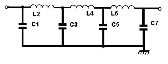
- Chebyshev type I filters with equiripple in the passband and a monotonically falling, maximally flat stopband. A 7-pole version with three inductors and four capacitors in a pi-network has been around for a while, in e.g. the old recommendation from the GQRP club. It was based on the QST paper “Low-pass filters for amateur radio transmitters,” Ed Wetherhold, W3NQN, Dec. 1979. Two designs for a 20 m filter were given there:
1) Max. ripple in passband: 0.00731 dB, attenuation at 28 MHz: 40.7 dB
1) Max. ripple in passband: 0.00960 dB, attenuation at 28 MHz: 34.5 dB 
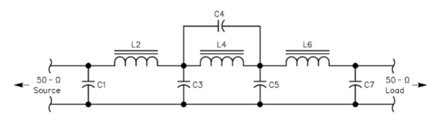
Second-harmonic optimized low-pass filter from the
GQRP data sheet (issue 2)An improved stopband was the topic of W3NQN’s article “Second-harmonic optimized low-pass filters” in QST Feb. 1999. Here there is one additional capacitor as the central inductor is made into a parallel resonance which gives a zero in the stopband, based on an idea by Jum Tonne, WB6BLD. The design goal is that this zero should be at the second harmonic frequency. W3NQN proposed to call this a Chebyshev filter with a zero (CWAZ) filter, but it is more correct to call it a quasi- or pseudo-elliptic filter as remarked by G3TMG. It increases the attenuation at the second-harmonic in the 20 m design to better than 60 dB. This design is the basis for the current (Issue 2) G-QRP technical sheet. This would also be interesting to test in the QRP Labs Ultimate 3 transmitter kit.

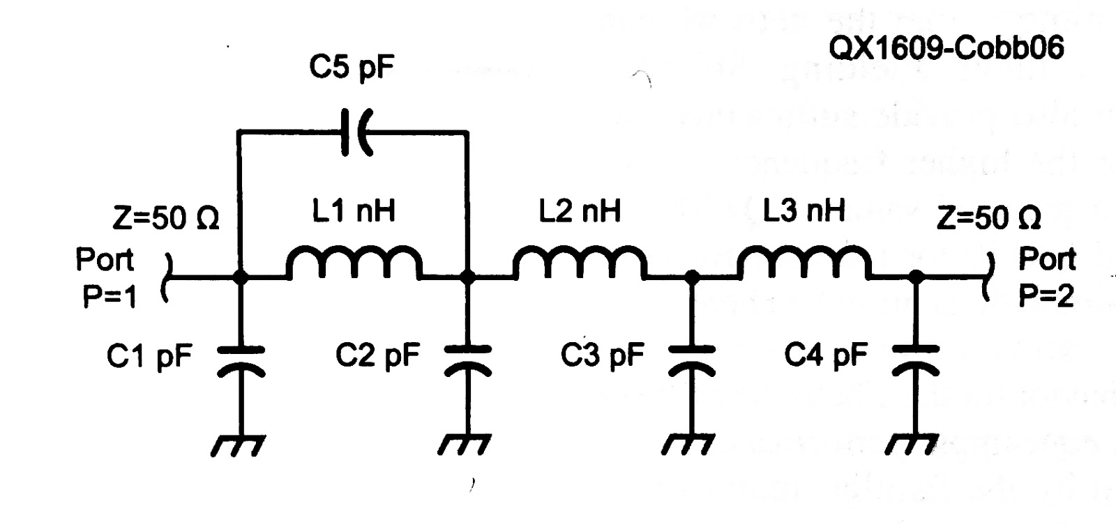
Zolotarev low-pass filter from the Nov/Dec 2016 QEX article G3TMG in the new QEX articles has noticed that the passband is over-specified in the above filters as the lower 60% or so of the passband is unused. The Zolotarev design allows for more passband ripple in this part where it does not matter. The advantage is even better stopband attenuation. A measured example for a 60 m filter has a passband ripple of 0.17 dB and a stopband attenuation at the second harmonic of 71 dB. This filter has the same component count as the previous one, but the filter is no longer symmetric like the two previous ones. The increase in second-harmonic suppression is not as great as the going from the first filters to the second, but should still be worth the effort.
- Gary Cobb, G3TMG, Zolotarev low-pass filter design, QEX, July/Aug 2016.
- Gary Cobb, G3TMG, A more efficient low-pass filter, QEX, Nov/Dec 2016.
Even better low-pass filters for transmitters
The last issues of QEX have featured two interesting articles by Gary Cobb, G3TMG. He outlines the advantage of using Zolotarev designs for the harmonic suppression filters of transmitters, giving even better suppression of the second harmonic than the more common Chebyshev or quasi-elliptic filters.
|
| Chebyshev low-pass filter from the GQRP data sheet (issue 1) |
My interest in this was triggered by the test of the Ultimate 3 QRSS/WSPR kit from QRP Labs in the Nov 2016 QST. The review was positive overall, but it was remarked that the harmonic suppression does not meet FCC requirements (-43 dBc or better). I am not sure whether this is due to PCB layout issues, or if better filters can alleviate it, but I note that the design uses the simplest filter of the ones I have listed here.
The evolution of filters for use for harmonic suppression follows at least these three steps:
- Chebyshev type I filters with equiripple in the passband and a monotonically falling, maximally flat stopband. A 7-pole version with three inductors and four capacitors in a pi-network has been around for a while, in e.g. the old recommendation from the GQRP club. It was based on the QST paper “Low-pass filters for amateur radio transmitters,” Ed Wetherhold, W3NQN, Dec. 1979. Two designs for a 20 m filter were given there:
1) Max. ripple in passband: 0.00731 dB, attenuation at 28 MHz: 40.7 dB
1) Max. ripple in passband: 0.00960 dB, attenuation at 28 MHz: 34.5 dB Second-harmonic optimized low-pass filter from the
GQRP data sheet (issue 2)An improved stopband was the topic of W3NQN’s article “Second-harmonic optimized low-pass filters” in QST Feb. 1999. Here there is one additional capacitor as the central inductor is made into a parallel resonance which gives a zero in the stopband, based on an idea by Jim Tonne, WB6BLD. The design goal is that this zero should be at the second harmonic frequency. W3NQN proposed to call this a Chebyshev filter with a zero (CWAZ) filter, but it is more correct to call it a quasi- or pseudo-elliptic filter as remarked by G3TMG. It increases the attenuation at the second-harmonic in the 20 m design to better than 60 dB. This design is the basis for the current (Issue 2) G-QRP technical sheet. This would also be interesting to test in the QRP Labs Ultimate 3 transmitter kit.
Zolotarev low-pass filter from the Nov/Dec 2016 QEX article G3TMG in the new QEX articles has noticed that the passband is over-specified in the above filters as the lower 60% or so of the passband is unused. The Zolotarev design allows for more passband ripple in this part where it does not matter. The advantage is even better stopband attenuation. A measured example for a 60 m filter has a passband ripple of 0.17 dB and a stopband attenuation at the second harmonic of 71 dB. This filter has the same component count as the previous one, but the filter is no longer symmetric like the two previous ones. The increase in second-harmonic suppression is not as great as the going from the first filters to the second, but should still be worth the effort.
- Gary Cobb, G3TMG, Zolotarev low-pass filter design, QEX, July/Aug 2016.
- Gary Cobb, G3TMG, A more efficient low-pass filter, QEX, Nov/Dec 2016.
Ultimate software is up to date
As I have mentioned several times on this blog, I have thoroughly enjoyed WSPR modes ever since Hans, G0UPL came out with the first Ultimate QRSS/WSPR kit.
That means that I have three different versions of the kit. Since Hans has kept on updating the software and even published the compiled versions, it is also possible to upgrade even the old ones.
I have done that and the displays here show the Ultimate 3, the Ultimate 2, and the Ultimate 1 with the latest software.
It is possible to upgrade the chips in-circuit, but I found that it is simpler to remove the chip temporarily from the socket and move it to a simple veroboard with crystal oscillator components. It is connected to my Ebay version of the USBtinyISP.
All continents in one night on WSPR
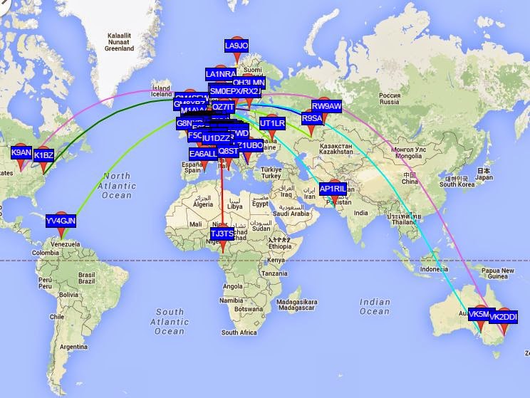
For me South America, Australia, and Africa are quite rare on WSPR. But they all heard my tiny 0.2 W signal the night between 31 March and 1 April in addition to North America, Asia and Europe. That’s a new one for me and worthy a brag post on the blog, I think! Hopefully, it may also inspire others to try low power WSPR.
In Australia and South America I was heard on the 10 MHz band, in Africa on 21 MHz, in Pakistan on 14 MHz, while 7 and 10 MHz worked into Siberia. North American stations also heard me on the 7 and 10 MHz bands.
This was on my untuned 80 m horizontal loop fed with open-wire feeder and a 4:1 balun. This shows both that the bare-foot Ultimate 3 kit is very tolerant of loads with SWR much different from 1, and that WSPR gives amazing results.


