Posts Tagged ‘RFI’
 What say you?
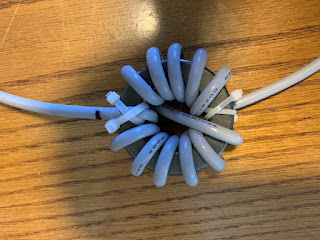
Here at VE9KK's household, my XYL has returned to part-time work from home and involves a computer and the internet to communicate regarding work. Last week while she was working and I was on the radio she told me her LAN connection kept dropping out. I did some experimenting and sure enough, it was my CW signal on 15m that was doing it. I quickly grabbed my last FT240-43 toroid and wrapped the CAT6 cable around it which did the trick!
I then did some reading and learned that the CAT cable should be loose around the toroid and not tight as this affects the small wire inside the CAT6. I also read that 7 turns were the magic number of turns. Finally and this is the question to my readers I read two thoughts on wrapping CAT cable around a toroid. One school of thought was it is perfectly fine and the other was it slowed down the internet speed? I never did a speed check on my wife's connection with and without the toroid. The reason for this is she never complained the speed dropped so why poke the bear! Has anyone out there had an issue with your HF signal dropping internet connections at home and what did you do about it?
 Time to make a choke balun
In your ham radio adventures, you may have heard the words..choke balun, feedline isolation, common mode choke or a 1:1 balun. In my humble opinion different names for the same device. These devices for the most part are present in a system to control common mode currents. I am not an engineer just a simple ham guy trying to sometimes understand some very complicated and technical explanations.
I hope to keep the next bunch of lines understandable. Here we go...what are common mode currents! Most ham use some form of 52 ohm coax as it's very easy to route, secure and can within reason be placed anywhere. Ideally, RF will flow out on the OUTER SURFACE of the coax INNER CONDUCTOR and flow back on the INSIDE SURFACE of the coax shield. This is what happens in a perfect world but if a system is unbalanced RF current will return on the OUTSIDE of the outer coax braid. It does not return but it radiates.
This is when we hams can experience RFI issues and these issues vary with the amount of common mode currents flowing on the outside of the shield of the coax. How does one control this common mode current? One very effective way is to introduce a common mode choke, 1:1 balun, choke, feed line isolation or whatever else it could be called.
In a previous post, I did go over how I installed a 1:1 balun at the antenna feed point of my Hustler 4BTV and that seemed to satisfy my RFI issues but further reading informed me that a choke balun at the radio feed point would be very advantageous. I ordered 2 FT240-31 mix toroids as I decided to make a choke balun instead of buying one. The two common mixes for HF toroids are 31 and 43. The difference being the 31 mix is effective from 1-300 Mhz and 43 is effective from 25-300 Mhz. I chose to go with the 31 mix and purchased 2 from a reputable dealer as not all toroids are created equal. I would be very wary if you find toroids at a very low price....just remember you get what you pay for. I ordered mine from Mouser Electronics Canada, part number 623-2631803802 made by Fair-Rite for 13.00 each.
I used RG8X coax to wind around the toroid but the issue with using a ring toroid compared to a split bead is I had to remove the PL-259 to wind the coax around the toroid and then solder the PL-259 back on. I intended to make 10 loops and for some reason, I ended up with 11 turns through the toroid. I then soldered the PL-259 connector back on but not before placing the barrel and coax spacer on....how many of us have soldered a PL-259 on and then realized we forgot the spacer and barrel!
Another advantage to having a choke balun at each end of the coax is that it helps remove some RF noise that is picked up on the shield of the coax.
 |
| Dont forget these BEFORE soldering the PL-259 |
 RFI noise antenna issue
I have decided to give my MFJ 1026 noise canceller a call to action and combat this RFI I have been having. In the past, I did own a 1026 and used it with great success to remove RFI our plasma TV was giving me. With the MFJ 1026, you need to have what is called a noise antenna and it has to hear the same RFI your main antenna is hearing. When I used this device to remove the plasma TV issue I had no problem getting the noise antenna to receive the RFI loud and clear.
This brings me to my head-scratching moment with the RFI issue I am having now. The first noise antenna I tried was my H-800 active antenna. I picked up nothing, I then placed it from vertical to horizontal without success. I then moved it around the property and still I was not able to hear the RFI. I then tried a long wire in the horizontal plane fairly close to my Endfed antenna and I picked up nothing. Again I moved this long wire around the property without success again.
I do have a spare Endfed that I used for portable use and I ran some coax outside to set up the Endfed close to the main Endfed and low and behold I picked up the RFI BUT it was way too close to my main antenna. The MFJ unit (via an internal light/fuse) was indicating far too much RF was making its way down the noise antenna.
The other thing I tried was the change the length of coax that feeds my main Endfed antenna but this made no change to the RFI issue. In July we are getting a new aluminum gutter installed and I may try using that as the noise antenna and see if that works. Up to this point I have not been able to pick up the RFI that the main antenna is picking up.....well other than almost putting a noise antenna ontop of the main antenna that as I said did not work out very well.
 Further investigation of my ongoing RFI.
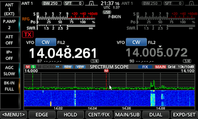 |
| A nice RFI free evening |
In a previous post regarding my RFI issues I kinda narrowed it down to my smart hydrometer. I am now starting to move away from that theory. The RFI is still there and I have been doing some reading regarding our smart meter and the frequency they use to transmit data does not jive with an HF harmonic and I have been logging the RFI and there are some on/off times for the RFI and when I visit the meter during off times the noise my AM radio picks up is still there and just as strong. I have therefore removed the smart meter as an issue.
About a month ago I received an email from a fellow ham who was dealing with some RFI and it seemed to be on a 12 hour on/off cycle. This got me thinking of a timer operated device, the ham had contacted hydro and they came by but really found no issues well none that seemed to connect to a 12 hour on/off cycle. I got to thinking and asked him to check with neighbours if they recently purchased a grow lamp system. A short time later he emailed me informing me that his neighbour in fact did purchase a grow lamp device. When the device was unplugged his RFI issue went away. He is now filtering up the grow system to remove his RFI issue.
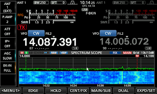 |
| RFI filled day |
Now back to my RFI issue, I have started to log the on/off times for my RFI and it for sure is not on a precise 12 hour on/off cycle BUT it seems to turn off at night. Many times between 23:00 to 23:30. Other times I have seen it off at 21:00 but I can say that it is off each night and the off time my vary. As for the on time it can vary from 07:30 to 10:00. I have also had occasion were it has been off most of the day as well. My understanding is that the device is being turned off/on by the owner and not a timer. Because most of the time the on time is about 12 hours I am thinking it too is a grown lamp.
I have asked the folks on both sides of me and have been told that neither have a grow system. I do understand they may not be telling me the truth as it really is none of my business. One of my neighbours I have been in his home and I can say that I have not seen a grow system anywhere. I have even wondered close to their homes when I have the RFI and I pick up nothing.
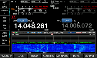 |
| Sometimes the RFI is not to bad |
I do have an MFJ 1026 noise cancelling unit and for this device to work you need to have a listening antenna that hears the same RFI as the main antenna. I have been playing around with noise antennas for a few weeks and my result will be in my next post.....I was very surprised and confused with the results.
 RFI issue solved!
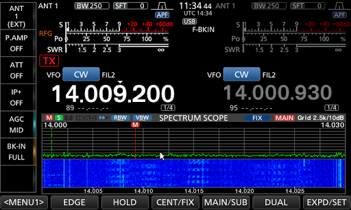 Back in May I posted regarding an RFI issue I was having and at the time I thought is was the neighbors heat pump. A few weeks ago my neighbor was away on business and his heat pump was off but my RFI was still present and more of it! I took my Eaton FRX5-BT put it on AM with the antenna up and took it for a walk about. When I passed by my Hydro smart meter the RFI was present big time but last time there was no issue at the meter. Upon investigation I read that the meter has cycles were it transmits data and thus the off and on issue with the RFI. The other issue is we are in very close proximity to other homes and I am certain my Endfed antenna is picking up not just my smart meter. The good new in all this is my Icom 7610 has great filtering and my NB is able to filter it out and the issues are gone. It's a problem that I can live with along side the rigs filtering.
 RFI on SOTA Summits
One thing to watch out for when doing SOTA activations is the presence of strong Radio Frequency Interference (RFI) on some peaks. The typical scenario is that the summit is also an established radio site with transmitters that interfere with your ham radio operations.

I use the VHF/UHF bands for SOTA, so I am writing from that perspective. My impression is that HF interference is much less likely because these radio sites don’t usually have any HF transmitters. However, they may have broadband noise sources such as networking equipment, power line arcing or switching power supplies that can create problems on HF. Anyway, this post is focused on 2 meters and higher bands.
In my experience, the transmitters at radio sites may include land mobile repeaters (VHF or UHF), NOAA Weather (162.xx MHz), TV/FM broadcast stations and mobile wireless (cellular) systems. The TV/FM broad stations are really bad news because they run a crapton of RF power.
The worst summit I have encountered is Sandia Crest (W5N/SI-001) near Albuquerque, NM. See trip report here. They even have a sign in the parking lot to warn you that the RFI may wipe out your car’s keyless remote.

Some other notable RFI-heavy SOTA summits are Monarch Ridge South (W0C/SP-058), Squaw Mountain (W0C/PR-082), Terry Peak (W0D/NW-002), and Greentop (W4T/SU-076).
In a high RFI environment, your radio receiver gets overloaded such that you can’t hear stations calling you but they can hear you just fine. This results in the SOTA activator calling and calling while the chasers get frustrated that the activator never hears their call. Not good. It may not be obvious that this is happening. This blocking of the receiver may come and go, depending on which transmitters happen to be active.
Mitigation Strategies
There are a few things that you can do to deal with the RFI:
Move Away From The Source
Probably the first thing to try is just moving away from the source of interference. This may mean moving away from the highest point on the summit but it may be better overall to give up a few feet of elevation to not have the interference. You’ll need to stay in the activation zone to be a legitimate SOTA activation.
Use A Better Radio
Some radios are better than others when it comes to receiver performance including the ability to reject unwanted signals. The low cost radios from China (Baofeng or similar) generally have lousy receivers so they are a poor choice for operating from an RFI-intense summit. Many people report better results with the Yaesu FT-60, a solid performer. Commerical radios from Motorola are even more robust. I’ve been using a small mobile radio for SOTA (Yaesu FT-90) which outperforms most handheld radios.
Change Your Antenna
Using a directional antenna can help…just point it away from the source of the interference. Oddly enough, using a worse performing antenna can help improve your ability to communicate. For example, a rubber duck antenna on a handheld radio will allow less of the interfering signal to get into your receiver which may improve your ability to receive. As long as the antenna is “good enough” to complete the radio contact, it may be the way to go. One trick I’ve used is to deploy two radios, one for receive with a crummy antenna and the other for transmit with a better antenna. That way, you still radiate a stronger signal while reducing the interference into the receiver.
Use A Bandpass Filter
You can insert a filter into your antenna feedline to reduce the interfering signal. The best approach is to use a bandpass filter that passes the frequency you are operating on but attenuates other signals. SOTABeams offers a compact bandpass filter for the 2m band. (Note that it has a 5W power rating which is fine for handheld radios but not more powerful transceivers.) DCI Digital Communications offers higher power filters but they are much larger in size.
Change Frequency
Sometimes a small change in frequency might help a bit if the interference is limited to certain frequencies. Another tip is to try another band. That is, if you are getting interference on 2 meters, you may find that the 70 cm band is better. Or vice versa. It all depends on the transmitters at the site.
73 Bob K0NR
The post RFI on SOTA Summits appeared first on The KØNR Radio Site.
 RFI mystery
 |
| RFI issue spread across the band |
- Switched to my active antenna and I still had the issue.
- I change to battery power only and I still had the issue.
- I turned off the main AC circuit breaker to the house and I still had the issue while using battery power obviously. Oh and an added note.....my dear wife was not happy about that.
 |
| Sometimes the RFI stops but then soon starts |
-Switched to my dummy load and the issue was gone but so were all signals.
So from the above, it seems it is being picked up by the antenna and not something within my home. At this point, I have not tried to pinpoint times as to when or if the RFI is present. I will be within the next few weeks paying very close attention to times when I am on and if the RFI is present or not. Until then I wanted to see if I was able to solve the issue with the Icom 7610's filtering. The choices I have are the noise reduction option or the noise blanker option. As a side note, my previous rig was the Elecraft K3 and it had amazing filtering for RFI issues. It was time to put the Icom 7610 to the test and see how it performed. I tried both the NR and NB and found it was the NB (noise blanker) that did the trick. I was able to totally remove the RFI and still hear the CW signal that was getting buried in the noise. Within the noise blanker settings, you can adjust the level, depth and width. I did find certain settings worked better than others at removing the offending RFI. I did change over to my Elecraft KX3 just to see how it dealt with the RFI and I was shocked how it really was not able to remove the RFI and the Icom 7610 won hands down!
 |
| The split-mini |


