Posts Tagged ‘Propeller’
 Propellor on Packet
My Gadget Gangster Parallax Propellor board has just modulated its first APRS packets. This is not down to any clever programming by me. I simply used the Spin APRS Object published by Richard, G3CWI based on code by Alex Erlank.
Richard had to make some changes to get Alex’s code to work and I had to change a few things as well. Mostly they involved replacing Richard’s callsign and position with my own! The AFSK output was connected to the mic input of my old TH-205E using a 0.1uF DC blocking capacitor. There is enough idle time at the start of the packet for VOX to be used if the transceiver supports it. Mine doesn’t, so for test purposes I manually keyed the radio’s PTT.

I found that my packets were not decoded by the Kenwood TM-D710 TNC when I used the option to include a path such as WIDE1-1,WIDE2-1. I’m not up to debugging the code. However, Richard had mentioned that calls less than 6 characters long needed to be padded with spaces so thanks to an inspired guess I found that that this applies to paths like WIDE1 as well.
There is a GPS object included with the code. I haven’t tried the Propellor with my GPS module yet, mainly because the GPS doesn’t pick up any satellites from inside the shack so I’d need to rig up a battery supply and take all the kit out to the garden to test it, where it’s damp and cold. (Yes I know, I’m a wimp.)
The AX25 object contains a section intriguingly called “demodulator” which has been removed. So it seems that there may be some Spin code that would enable the Propeller to be used as a TNC to decode and display APRS packets. That isn’t something I had particularly planned to do, but it would be interesting to see if it works better than the WB8WGA PIC based TNC that I built a year ago which is a bit fussy about the level of the input audio.
One of the options with the Propeller is a touch screen colour TFT display panel. With one of those a suitably clever person could make a very nice standalone APRS terminal. I think there’s an Ethernet module as well, so it could even be an IGate…
Prop drift uncovered
Yesterday I wrote that I was shelving the Propeller beacon project after discovering that the frequency stability is unacceptabe. Eldon WA0UMH persuaded me to try some tests to identify the cause of the drift. My conclusion is that it is a combination of factors.
The major factor causing the drift is the power supply voltage. Whilst developing the beacon using just the Gadget Gangster board I was powering it with a 6V supply – the minimum needed. After adding a PA I needed to increase the supply voltage to 9V. The drift is greater with 9V, regardless of whether the PA is actually connected.
| Looking down on the Propeller board |
If you look down at the Gadget Gangster Propeller USB board there are two SMT chips to the left of the Propeller and its clock crystal which appear to be voltage regulators. There is a 5V regulator a few millimetres to the left of the 10MHz crystal and a 3.3V regulator below it. The greater the supply voltage, the more heat the 5V regulator has to dissipate. Plugging the LCD UI board on top of the Propeller board traps in more of that heat making the drift even worse. This is not the first time I have discovered that voltage regulators and crystal oscillators don’t go well together.
Whilst it is useful to know what is causing the drift, my discovery has not indicated an easy solution. Either I use a temperature compensated 10MHz crystal oscillator as suggested by one of my readers, or I use the Prop to control an outboard and more stable synthesized oscillator. The first option looks the easiest, but the TCXO is not an inexpensive component.
Disastrous drift
I have decided to shelve the Propeller Beacon project. Actually the project made the decision for itself. Bored with receiving spots for my 250mW WSPR signal on 30m I decided to try 20m where there are almost as many monitors. But after a handful of spots there was nothing. After a while I decided something must be wrong.
I checked that the beacon was still transmitting at the right times and it was. So I switched on the K3, ran the WSPR software and the reason for the lack of spots became clear. My signal was drifting the best part of 10Hz in each two minute cycle!
When I first ran the beacon on the bare Propeller board I had found the signal to be pretty stable after only a few minutes warm-up. After adding the LCD board – which plugs on top of the Propeller board – I noticed that my 30m transmissions were being quite consistently reported with -3Hz drift. The RF amplifier board with its heatsink is separate from the Propeller board and nowhere near its crystal oscillator. I hypothesized that the LCD board is trapping some heat in, enough to make the master clock oscillator drift.
The drift is probably a multiplication factor of the clock frequency so the higher in frequency you go, the worse the drift. Whatever the explanation, the Propeller + LCD combination is not usable as a WSPR beacon as it is.
It seems to me that there are two possible solutions. One would be to make my own Propeller processor board with a temperature controlled crystal clock. The other would be to use the Prop to control a Si570 synthesizer or something like that. Unfortunately I don’t think either of those solutions are within my capabilities just at the moment. So I’m afraid the beacon project will be going on the shelf.
Propeller programming problems
Eldon WA0UWH posted yesterday on lessons learned about the Parallax Propeller programming language Spin. I too have been having fun and games trying to create a user interface for my multimode multiband beacon using the LCD module. Whilst some of my problems have been due to my failure to spot my own stupid mistakes, a couple were caused by the tools themselves.
A considerable amount of time was wasted recovering a working program after a change I made seemed to have messed it up. Eventually I discovered by accident that the program fails to run correctly on the Propeller board unless the main Spin source file is the foremost one in the Propeller Tool editor. I had begun splitting my code into separate objects with their own source files and because I had been editing or referring to one of these files I had tried running the code with one of these files in the foreground instead of the main one.
I wasted a couple of hours trying to backtrack what I had done and ended up installing one of those programs that archives each version of a file whenever you save it so that you can roll back to a previous state. The best program I have found for this is AJC Active Backup which comes with a diff tool that shows the differences between two files but unfortunately I have lost the licence key since the last time I installed it so as I was feeling tight-fisted I had to use something less good.
The other problem that caused a lot of lost time was an apparent error in the LCD UI Spin object. Specifically, the cursor method that is supposed to let you change the cursor to a flashing underscore or block just seems to clear the LCD and then crash. I had been hoping to use the cursor to show what bit of information the user was editing but I can’t get it to work.
I’m not sure exactly where I am going with the beacon project. Jeff KO7M has developed a WSPR encoder that generates the required code when you input your call, power and locator. However there is not much point in using it unless I provide an interface that allows you to input this information as text. If I choose to support Opera then the bit code will have to be programmed in as no-one other than Opera’s programmer knows the algorithm used to encode the callsign. As my beacon is unlikely to be used by anyone other than G4ILO in IO84 at however much dBm it produces I may as well hard code all beacon texts.
The other thing I’m not sure about is how to add the PA. The LCD UI module is now plugged into all the headers on the Gadget Gangster board and I don’t want to attach wires to the board itself. I could solder headers to the two rows of holes adjacent to the existing headers on the Gangster board and then plug a board to the bottom of it. That would be the probably be the neatest solution – unless anyone has a better idea?
Propeller crash
Yesterday I had another of those days that nearly made me decide to hang up my soldering iron for good. Some readers may have spotted the despondent blog post I made before I deleted it.
I assembled the Propeller LCD UI module. It went together easily and I had no trouble with the soldering using a magnifying lens (a strong pair of clip-on reading glasses clipped on to my normal reading spectacles) and resting my soldering hand on the desk to stop the shakes. But Murphy was not going to let me get off that easily.
Preparing to test the UI board I realized that I had skipped a page of the instructions and had not soldered a connector to the LCD daughter board. I thought that a connector for the main board (a male 8 x 2 box header) had been omitted from the kit so I had installed one of my own. When I picked up the daughter board I saw the two rows of 8 holes and without thinking installed the 8 x 2 plain header that came with the kit. Also male. When I realized my mistake bad words were said. In all my years of kit building I have never before done anything quite so stupid.
I recalled Don Wilhelm W3FPR’s advice to K2 builders who install multi-pin connectors on the wrong side of the board to sacrifice the connector and not try to remove it intact. This I eventually did with Olga’s help. She suggested I place the soldering iron body along the row of soldered joints to melt all of them so the connector would fall out. That didn’t work, but it did soften the plastic part of the connector allowing it to be pulled away. I could then remove each pin one at a time and clean up the through holes using one of Olga’s sewing needles. Finally I was able to install the four 1 x 4 female headers that had presumably been supplied with the kit as a replacement for an 8 x 2 female that was really needed.
After all that stress (both to me and the board) I was relieved that when I plugged it in to the Propeller board and ran the demo program the UI module worked. But my happiness was short-lived. After I tried some modifications to the program I found that it seeemed to be crashing. The program would start at switch-on but would eventually hand up and not respond to the buttons. Sometimes garbage appeared on the LCD. The time before this happened got shorter with each attempt until sometimes the Propeller wouldn’t even respond to the reset button. I restored the original program in case my changes were to blame, but the device was still crashing.
Next I re-heated all the solder joints I had made, though they all looked OK. On reassembly the Propeller still crashed. Thoroughly despondent by this point I typed a post describing what happened in the hope that someone would offer to come to my rescue (thanks to those who did.)
After a rest it occurred to me that I had crashed the Propeller by dropping the board a centimetre or so on to the desk. There was probably still a bad connection somewhere. I re-soldered all the joints, including all the ones on the main Propeller board. That had been ready assembled. I guess that the manufacturer had used lead-free solder because I couldn’t melt the joints until I applied a bit of my own leaded solder to each one. Then all the joints looked nice and shiny.
After that treatment everything worked and up until now, cross fingers and touch wood, has continued to do so. So it seems that a poor soldered joint in the manufactured board was the cause of my problem! Thank you, Murphy, but I don’t need your help. We do this for fun, do we?
Now output
Everyone who commented to my last post about the lack of output from the Kits and Parts RF amp felt that the problem had to be the QRPer’s curse – the toroid inductor. Normally I don’t have a problem with toroids, but when they are so small that your thumb obscures the whole core while you are holding it, never mind winding it, they are not the easiest of components to work with.
So I gritted my teeth, tried to forget the hour I’d spent yesterday wrestling the thing into position, and yanked it out. One of the wires broke off in the hole leaving nothing to grab on to. I was unable to clear the small plated-through holes in any case. What I was able to do was melt the solder enough to push some bare wire through, creating “pins” that I could solder to. I twisted together the two wires that are connected so I had three ends to solder to the three pins I created. The toroid now stands up on the board a bit but it was easier soldering to the pins than trying to get four thin wires to go through four holes simultaneously. To my joy, on applying power and RF the power meter showed output.
I’m getting about 150mW if the amp is supplied with the recommended 8V, and just about 200mW from a 9V supply. That’s only about 10dB of gain, a bit less than expected but probably enough given that the Propeller does not generate the purest of signals. The WSPR beacon has already been spotted a few times in Germany. But the 2N5109 runs a bit hot to the touch so I’ll have to QRT until the heatsink I ordered arrives. In the meantime I still have the LCD UI board to assemble and play with.
Some assembly required
Yesterday a packet from the USA dropped on to the doormat. It was the LCD UI module from Gadget Gangster. The cheap international shipping option is pretty quick!
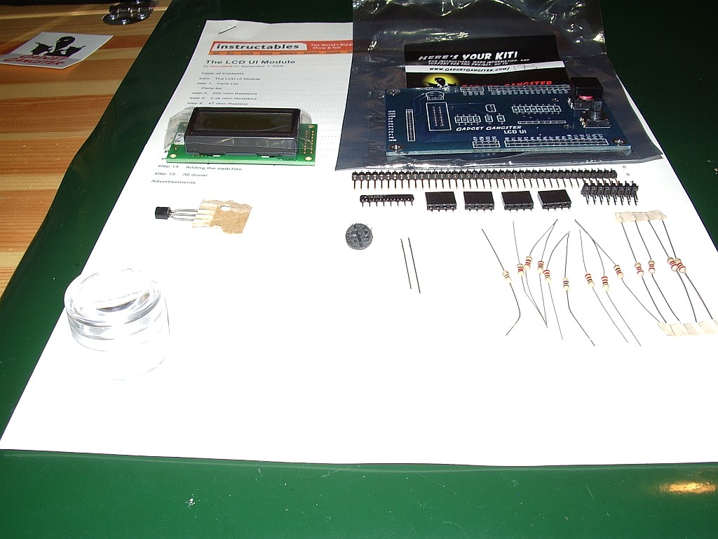 |
| LCD UI module ready for assembly |
On opening the envelope I was taken by surprise as I hadn’t realized the module was a kit. But there aren’t too many components and they are all through-hole so I should be able to manage it. I will take my time and double check everything to ensure I don’t do anything stupid like solder headers on the wrong side of the board. More than a few K2 builders have done that!
The instructions on the Gadget Gangster website are very comprehensive with several colour photos showing different stages of assembly. But on checking the parts against the parts list I found that I was missing one 2×8-pin header socket. Fortunately I found one (a pack of 2 actually) for a couple of quid from a UK based eBay component supplier so I should have it in a couple of days. eBay is my main source of electronic components these days as the usual sources like Farnell or Maplin all have hefty minimum order and postage charges that make ordering the single part you need to complete a project quite uneconomic.
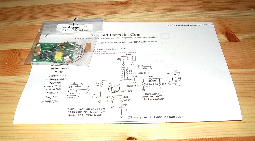 |
| Kits and Parts Universal RF Amplifier |
A few days earlier I received another kit from the USA: a QRP RF amplifier from Kits and Parts. I got this with the idea of using it with my Propeller beacon but it is probably too good for that. The beacon really needs only a simple class C amplifier to raise its output to a couple of hundred milliwatts. I had been tempted to go for a couple of watts but whilst WSPRing on 20m today and monitoring the signal on the K2 I noticed a weak in-band spurious around 14.05 MHz which no low-pass filter will eliminate. So it is probably best to stick to QRPp if using the Propeller as an RF source.
Another new arrival in the G4ILO shack was a GPS module from Hong Kong. This was used, ex-equipment, and cost about £12 including postage. I’m not sure what I am going to use it for but if I don’t put it in the beacon to provide a time reference (and locator) for WSPR it would be interesting to try to make an APRS tracker using the Propeller chip.
So many projects! But I am convinced that having this amateur radio hobby to give me so many different and interesting activities is the reason I remain cheerful and positive unlike so many people who have the same health condition and seem to fall into a slough of despond and hopelessness. I may never complete them but at least they give me something to stop me dwelling on darker thoughts.


