 |
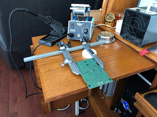
| The condo kit corner. |
About a month ago my
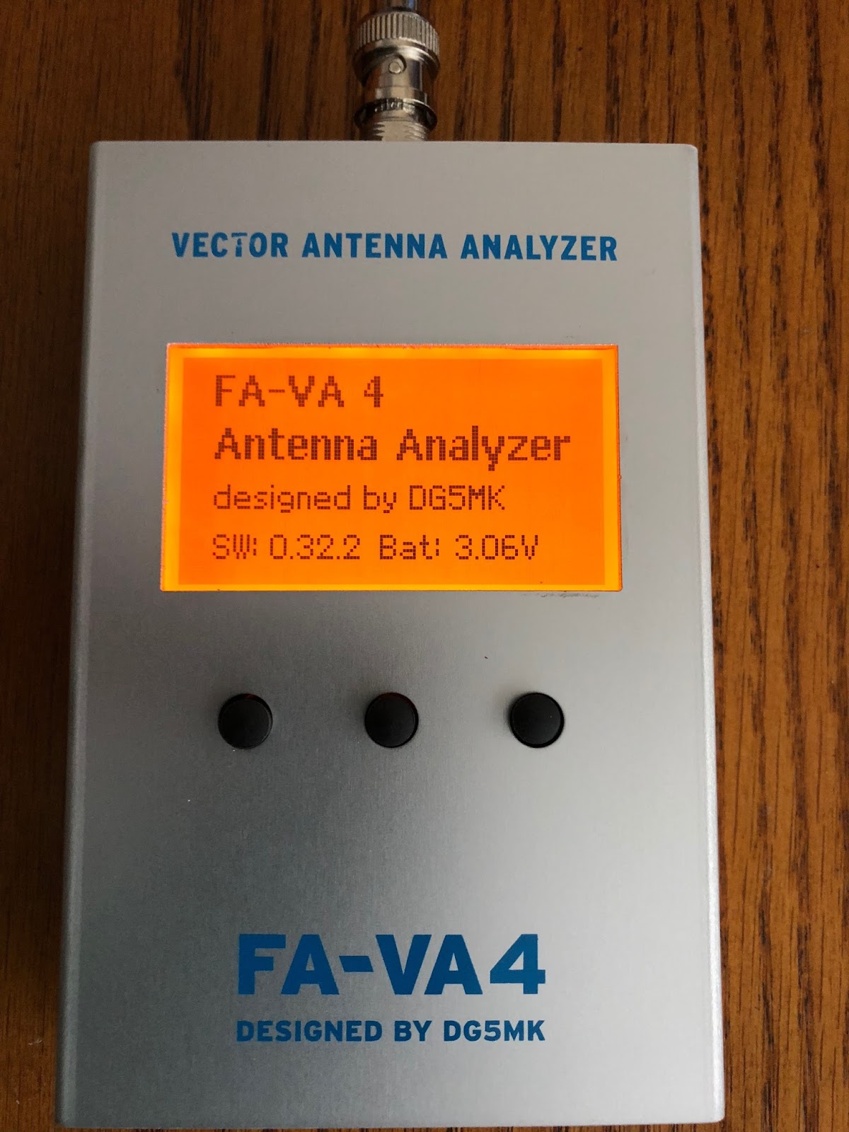
FA-VA4 vector antenna analyzer kit came in and it has sat idle until Friday. I had the day off and with everything done that needed to be done, I say "everything that needed to be done" because there is always something to get done! I decided it was time to put the kit together. This really is the first kit I have attempted to assemble since moving into our small condo in Toronto. I no longer have the huge desk, nice lighting and the room to place all my equipment around me. Now it's a roll top desk with 2 slide out shelves, that is my only choice for kit work now. Trying to get the exhaust fan, soldering station and other small miscellaneous items in place is a real challenge. What was also a challenge was remembering where the heck I placed things in the dam condo! I have a nice
Panavise setup for holding my boards in place while soldering. I could find the arms but I was not able to locate the base. I looked everywhere but had no luck and nothing bothers me more than knowing it's somewhere but just not able to find that "somewhere". I had to settle for placing just the Panavise arms on the slide out and do my best. I found very quickly that working in a tight space one has to be very aware of cords and tools, a few times moving the soldering iron in place almost had the soldering iron cord take the make shift Panavise (holding the circuit board) onto the floor. The kit from Box73 comes from Germany, the shipping time was fantastic as well as packaging. There is no SMD work to be done that was done and I only had to mount some connectors, power on switch, pushbuttons and the LCD display. After being away from kit building for a very long time this was a nice way to jump back into things. I first took an inventory of the parts and this is something I always do. I hate getting to the point when a part can't be found and your not sure if it was not shipped or misplaced by me? Doing the inventory allows me to contact the vendor and in the case of large projects the part arrives in time for that point in the assembly. Everything was there and it was now time for the next important step...read over ALL the assembly instructions. In my case I go the extra step and check out YouTube videos and the internet to see if there are any pointers that others have come across to make things easier or things to avoid. One of the builder beware tips I read was from
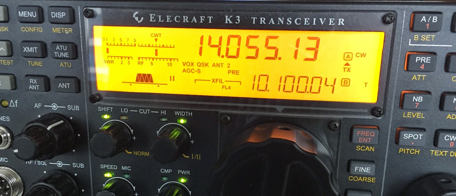
John AE5X blog to not use lithium batteries as the voltage is to high and the FA-VA4 will repeatedly reboot. This type of information is invaluable when kit building. It saves trouble shooting time and going down possibly a long road of parts testing.
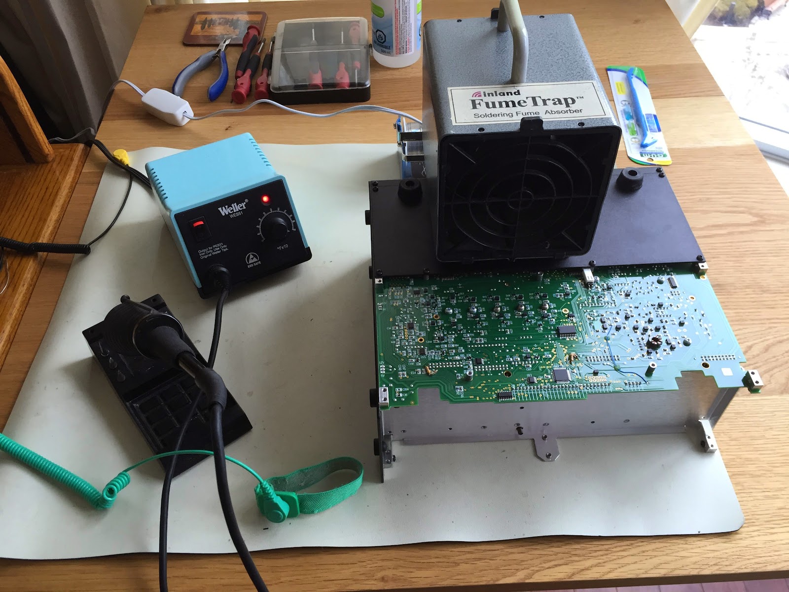
This kit does have SMD parts that I said are factory installed BUT some of the items that the builder needs to install are very close to some SMD parts. This brings me to another important part of kit building....spend the money to get the right tools for the job. In this case my
Weller WES51 has a large variety of soldering tips. I find the fine chisel tip (Weller ETM) worked great for soldering the LCD terminals, the larger tip for the BNC connector (Weller ETD) and finally the intermediate tip for the components beside SMD parts( Weller ETB).
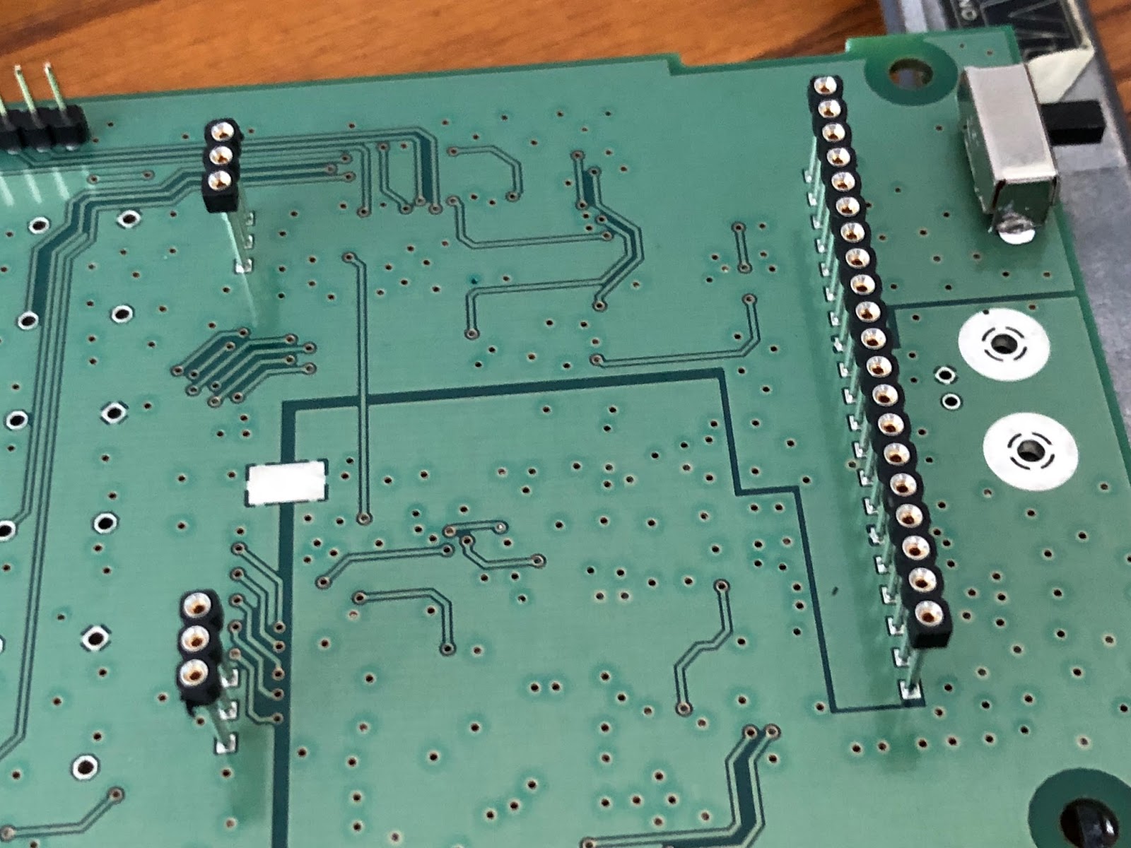
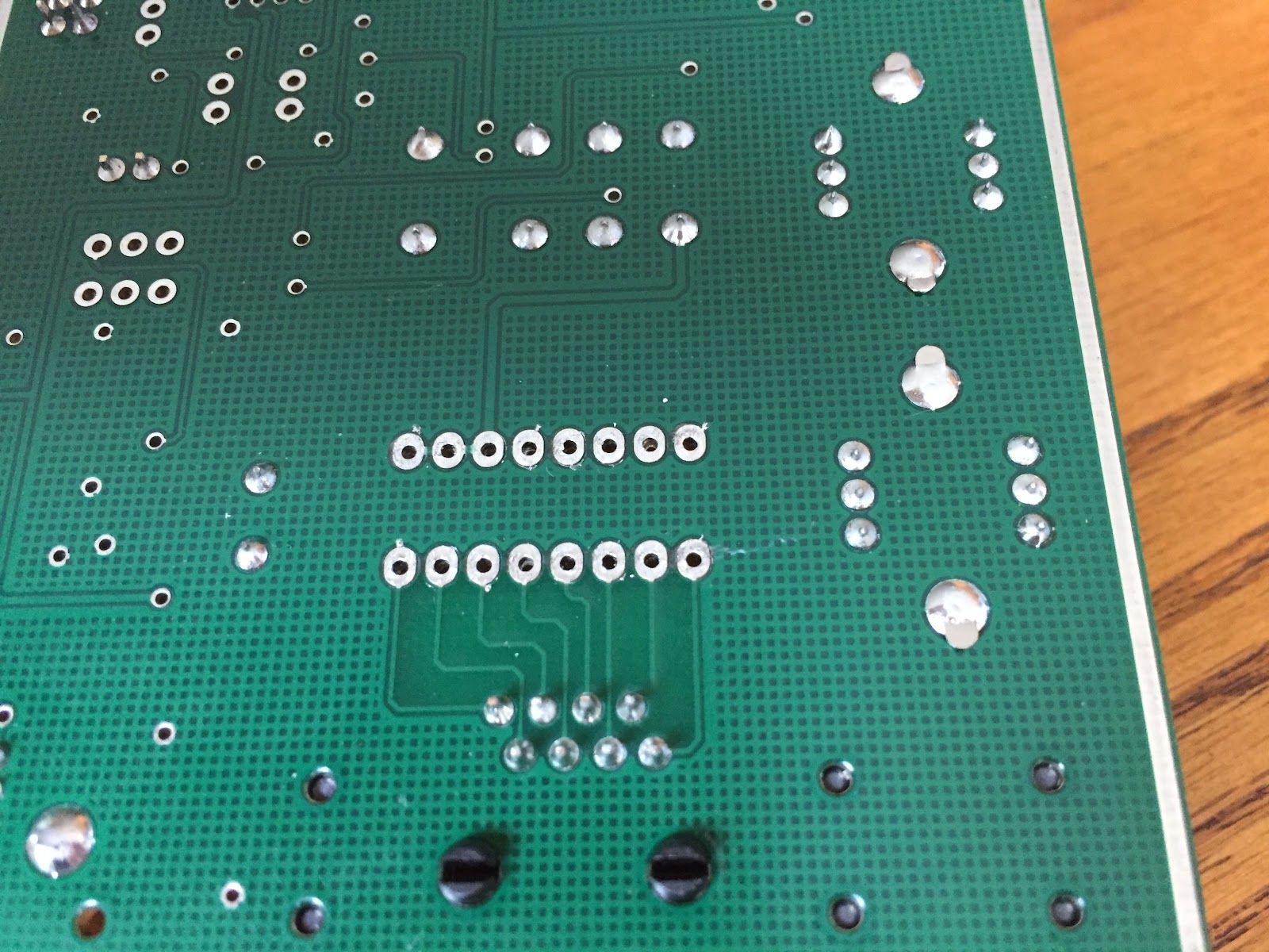
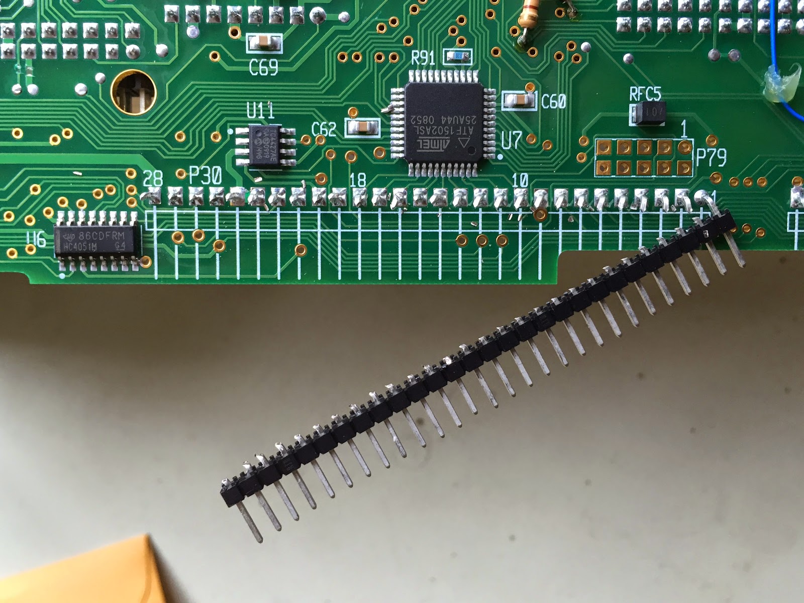
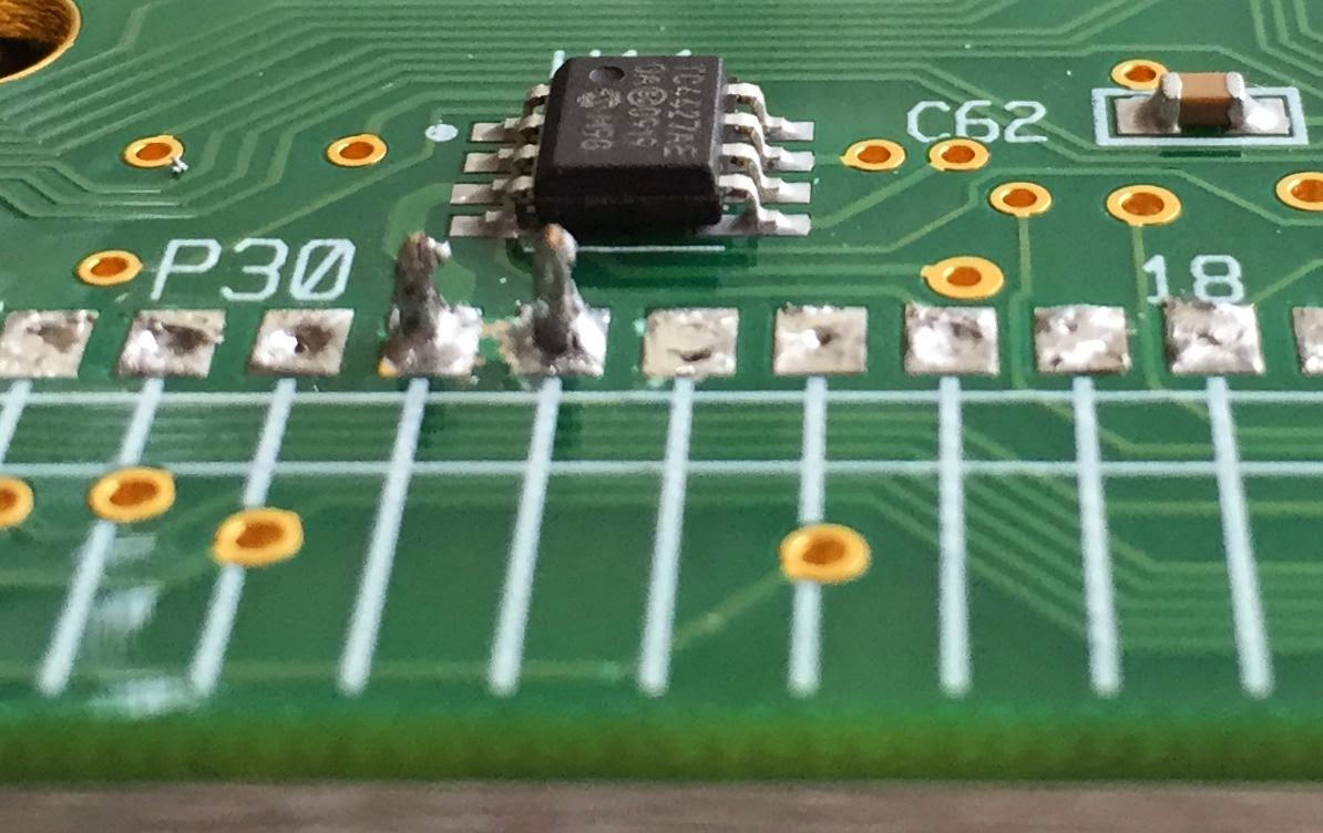
The instructions had me installing the ON/OFF slider switch first and this was a great start for this old rusty kit builder. I then moved onto the 3 rails in which the LCD would eventually plug into. You will notice from the picture these are raised up on the board. Each pin has a "collar" so the rail will be at the proper hight but the builder has to be cautious and make sure the rail is firmly seated and upright and straight. One rail is 20 pins and once it's in....it's in! In the past I have had to remove these types of components due to my own lack of attention. IT IS NOT FUN and I have a
Hakko desoldering tool which make desoldering a pleasure but even with that tool removing a 20 pin rail is not fun at all. Take the time to set these parts up for first time correct soldering. My method was taping the rail in place, solder the 2 opposite end pins, check for upright correctness and firm seating on the board. If all is good solder the remaining pins. The other components were easy to solder in place when using the proper tips. I have a
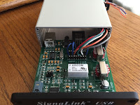
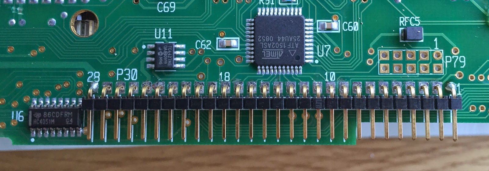
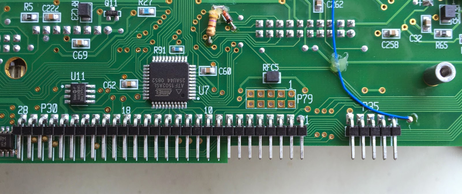
magnifier head set and use it to make sure all connections are soldered properly and that all were done. You would be surprised how many times when multiple pins are involved how easy it is to miss a pin. The LCD needed to be soldered to the backlight, it involved a 20 pin connection on one side. The instructions said I only "had" to solder the 2 outside pins. I chose to solder all 20 and then on the opposite side of the LCD there were 2 sets of 3 pin connections that need all pins soldered. To make sure the LCD was firmly against the backlight I used some tape. Once the LCD was ready to go again I took time to inspect the pins that were going to plug into the 20 pin and two 3 pin rails. I did find one of the 3 pin setups ups on the LCD was bent! I corrected this but if I failed to see this could had resulted in broken or bent pins.
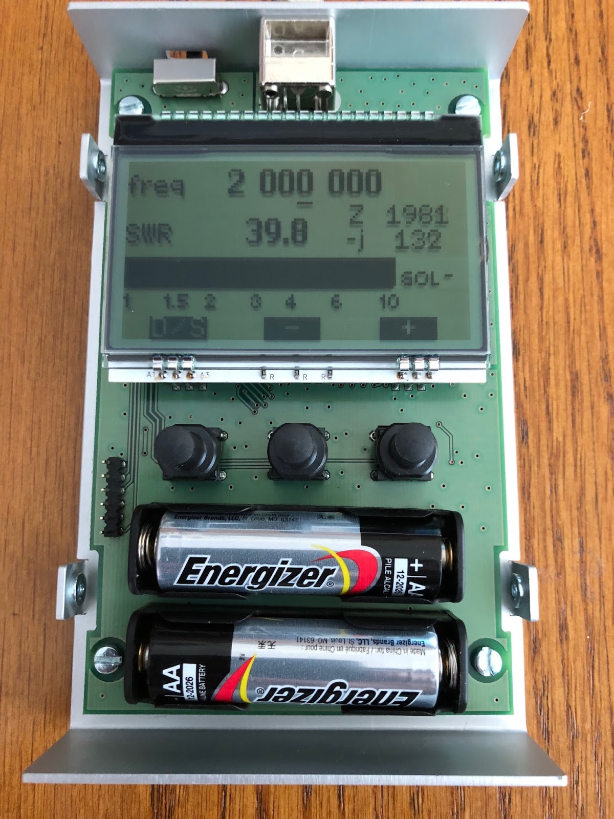
There is two AA battery holders that need to be soldered in and all I can say is check and double check this. Mixing this up polarity can bring smoke to the smoke test. Believe me it can happen. One of the Elecraft K2 kits I put together almost ended in disaster when I was not paying attention and soldered up a power cable with Anderson pole connectors. I soldered red wire to Anderson black connector and black wire to Anderson red connector. It gets better.....I then plunged it into the K2 and powered the K2 on!! The Astron power supply made a noise and both the inline fuses on the main Astron power supply blew. I was very luck and now double check everything.
It was now time for the "smoke test" and I was so proud of my first kit in over 4 years I had my dear wife Julie come over for the ceremony.......I flipped the switch and........yup you guessed it...NOTHING!!!!! Yup nothing.....but no smoke and that is a good sign. Julie giggled and moved on to other tasks. I made a mental note to always solo a smoke test and avoid the embarrassment. The problem was one of the AA batteries was not firmly in place. Once looked after the power on test was a success. I called Julie over for her to check out the kit but it just did not have the same excitement. That was it for the kit building for the day I still have to preform the calibration. Over all the kit was a joy to put together and by way of some side notes. The case is a brushed aluminum with attention to detail such as counter sunk screws for securing case, the LCD and buttons lined up perfectly and a nice touch was not having stick on rubber feet (that always over time seem to come off and get lost) This kit came with pull through rubber feet. I still have to calibrate the unit and actually use it but that will be another day.
 |
| Completed kit |
 |
| Smoke test |
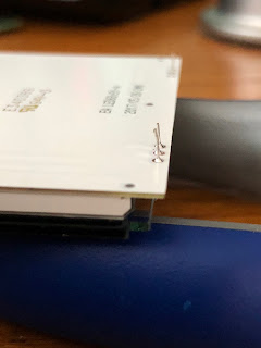 |
| Bent LCD pins |
 |
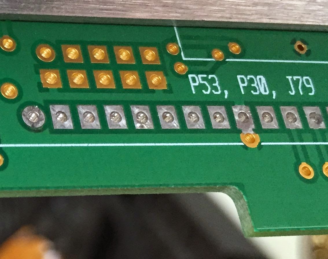
| Supporting the 20 pin connector. |
 |
| Completed LCD pins |
 Time to make a choke balun