Posts Tagged ‘power supply’
 Some radical thinking
Do we need those inline fuses between our radio and power supply, most if not all radios come with them but are they always needed? There was a time when I thought the more fusing the better and safer, but does it add to the safety or is it just redundant fusing? First off let me begin with, this is my own opinion and I do follow it whether you choose to or not it is absolutely up to you.
I was having an issue with my Icom 7610 cycling off and then back on again while transmitting . The issue was narrowed down to resistance within the cable from the power supply to the radio. I first replaced the poor terminal connections on my Astron power supply. The issue returned again it was then further determined that the guilty party was the inline fuse/fuse holder connection. I cut out both inline power cable fuses...OMG, you say?
Well, not really if (the big if) you have a power supply with very good built-in protection meaning over-voltage protection (crowbar), over-current protection (fold-back current protection), over-temperature shutdown and an internal AC fuse I believe you are good to go without inline DC fusing between power supply and your rig. Again in the background I hear "OMG, you did what"

If you don't need the inline protection then why is it there on most if not all rigs? The main reason is for mobile installations. The power supply is the car battery and there is no protection at the battery end for your rig. Also in the car, you have heat, cold, possible rodents, moving parts and so on around your power cables to your rig. Compared to home installation with a quality power supply your protection for a mobile installation is the inline fuses.
I do hear some saying "Wait what if there is an issue in my supply line from the power supply to the rig" This is true BUT keep the power cable as short as possible and if you have worries about overheating cables, moving parts or rodents then you have bigger issues than un-fused power cables. Having said that if something between the power supply to the radio power cable causes a sudden increase in current or voltage the power supply protection will quickly look after that.
Some who have a large rig such as the Icom 7610 or other manufacturers could be saying "there is no way this rig will be used as a mobile by the average ham but it has fused leads". My answer to that is the big 5 (Icom, Kenwood, Yaesu, Flex and Elecraft) have no idea what power supply you are going to use. Also, some may opt to use a deep cycle battery at home on a trickle charge or whatever.
After everything I have said about fuses I am not against them and as a matter of fact I have a Rigrunner fused rail and use it and I am thankful for it. I connect my external ATU, noise cancelling unit and SWR meter (for the light) to it.
Now if you have no issue with your supplied power to your radio and things are not acting up like they were with me then by all means keep the fused line but for me, some radical thinking cured the problem and some power supply understanding allows me to sleep at night knowing the radio is in good power supply hands.
Here we go again………

September last year I had an issue with my Icom 7610, it was shutting down and restarting. The issue was a supply low voltage situation. With the 7610 if the incoming voltage drops below 11.44 volts the radio turns off. This voltage drop happens during transmit (CW in my case) then the radio cycles off, the current draw stops and the voltage goes back up and the radio cycles back on again. This is a normal situation with the 7610 and is supposed to happen with a voltage drop at or below 11.44 volts DC. In my last post when this happened in September 2022 I narrowed it down to the Anderson power pole connectors for more details click the "In my last post link above.
On Wednesday I was taking part in the 1-hour CWops mini contest and out of the blue while transmitting my 7610 cycled off and then on again. I thought "Here we go again". I had a good idea where the problem was and to finish the contest I lowered my power from 100 watts to 50 watts. I have the Astron SS-30M power supply and for some reason beyond me, Astron decided to use screw-down terminals to connect your radio DC cables. It is a small slotted screw and to me just a problem waiting to happen. My old Astron power supply had studs with nuts and made a very solid connection. There is a new version of the Astron SS-30 and it offers Anderson connections on the front. But the screw type connections are still present on the back of the supply.
I decided it was time to do 2 things remove the inline automobile fuse holder and fuse on both the DC positive and negative radio cables supplied by Icom. It has been documented many times how these fuse holders have caused issues with voltage drop due to a poor connection over time. The other thing was a bit more ambitious which was to remove the screw-down positive and negative terminals on the Astron power supply. They were to be replaced with studs and nuts for a solid connection. 
Old screw terminals
The Astron power supply is out of warranty as for sure doing this mod would certainly void the warranty. So lets get started....The screws fastening on the cover of the power supply are Torx-type screws and you will need the proper tool to get the cover off. Once the cover was off I removed the positive and negative cables from the back of the screw-type connectors. These 2 connectors were removed from the power supply and put in their proper place.....the garbage! 
Out to the trash!
Two holes now had to be drilled in the case for the new studs and this is where success and disaster are a very fine line from one another. I placed tape on the inside and outside of the case as fewer filings from the drilling make their way into the power supply case. I also placed some protection on the inside of the power supply to also catch filings. I then marked off the holes and I used 3 drill bits to slowly move the hole up to the 3/8 size I was looking for. A word about the drill bits, I put a large amount of tape around the bit where I wanted it to stop once the hole was completed. No matter how good you are once that drill bit makes it way through the metal case it is going to want to keep going. You have a lot of pressure on that drill and well no one's reflexes are that good. I use the tape as a drill stop and it worked just fine as no damage was done to the parts in the power supply.
Drill bits
I used fibre inserts in the holes to insulate the studs from the case. These came from my other 20 amp Astron supply which are now on order from Astron. Then with the studs temporarily installed (no wires attached), I did a continuity check to ground and all was good, now the negative stud eventually does connect to ground and really does not matter but for poops and giggles I did it anyway.
I now connected the internal positive and negative wires to the studs and secured them. I then did the smoke test by turning on the power supply................all went well or this would be a much different blog post! I then tested the voltage at the Astron power supply new stud terminals and it was 13.86 VDC, then the cover when back on. I then added ring terminals to the Icom power cables (less the inline fuses and more on that in another post)
 |
| Marked and ready to go |
When I powered the Icom radio up and looked at the onboard voltage meter was reading 13.6 volts DC and during transmit using an FT8 carrier (into a dummy load) the voltage only dropped to 13.12 volts DC which is a great improvement.
 |
| Finish product |
DIY Powerpole voltage and current meters
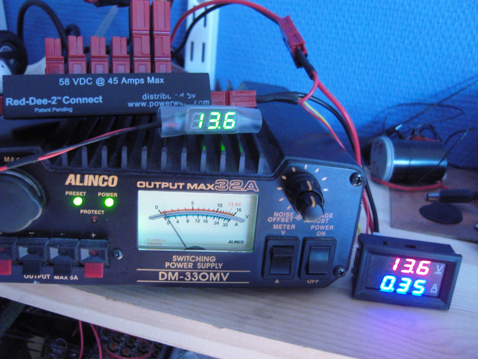
Powerpole voltage and current monitoring is quite nice to have. One can buy commercial meters, but due to the availability of nice and cheap modules, it is very easy to make them oneself.
To the right you’ll see my combined voltage and current meter as well as my volt-meter on top of the power supply.
Both of the modules have been bought on Ebay:
- Miniature 0-30 V DC LED 2 wire Digital voltmeter (371333527599) where the display is 22 by 10 mm. Cost slightly more than $1
- 0-100 V, 0-10 A Dual Voltmeter Ammeter (262455987311) costing less than $3. The module size is 48 x 29 x 26 mm and the letters are 7 mm tall just like the miniature voltage display.

DIY Powerpole voltage and current meters
Powerpole voltage and current monitoring is quite nice to have. One can buy commercial meters, but due to the availability of nice and cheap modules, it is very easy to make them oneself.
To the right you’ll see my combined voltage and current meter as well as my volt-meter on top of the power supply.
Both of the modules have been bought on Ebay:
- Miniature 0-30 V DC LED 2 wire Digital voltmeter (371333527599) where the display is 22 by 10 mm. Cost slightly more than $1
- 0-100 V, 0-10 A Dual Voltmeter Ammeter (262455987311) costing less than $3. The module size is 48 x 29 x 26 mm and the letters are 7 mm tall just like the miniature voltage display.
- Related post: “New gadget measures negative resistance“
Series capacitors that failed according to the book
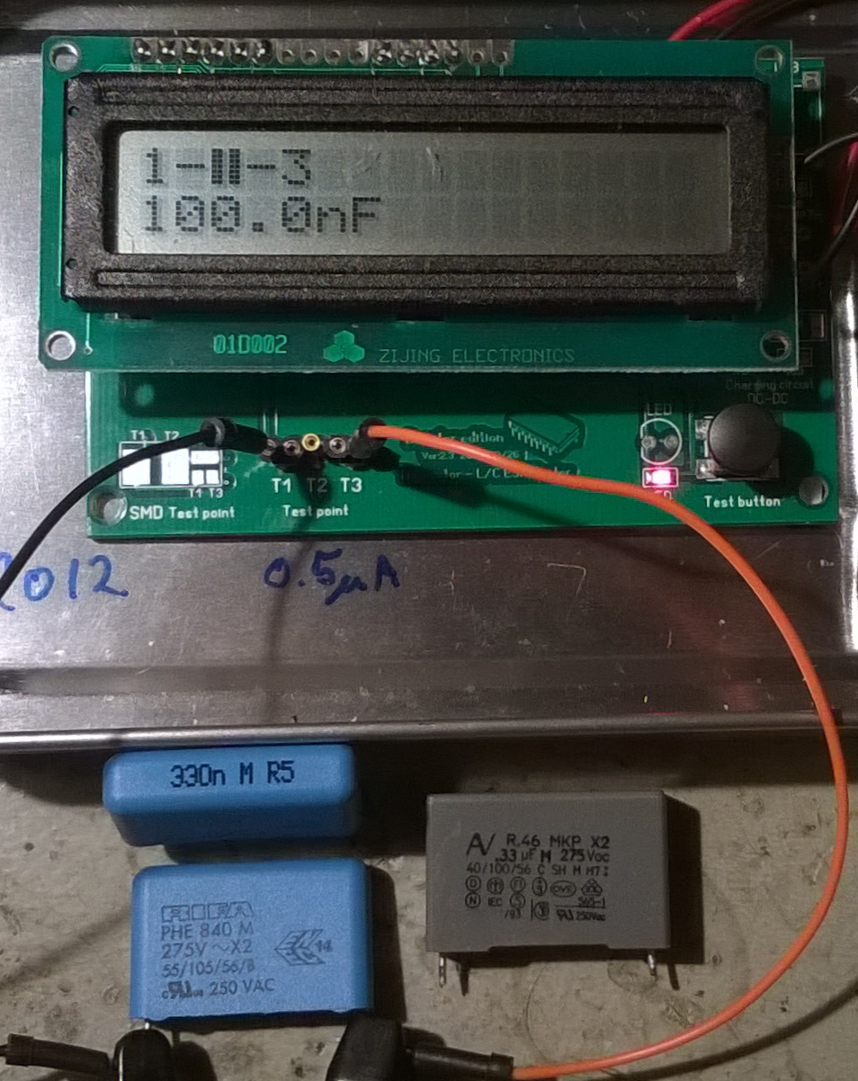 |
| 0.33 uF X2 capacitors which measured only 0.097, 0.1, and 0.118 uF. |
Many devices now use a capacitor power supply saving the space that a mains transformer occupies. The principle is that a series capacitor from the mains supply is used to drop the voltage and reduce the current. Provided that the circuit is completely isolated from human touch, this is an economical way to provide DC power.
The image shows three such capacitors as I were measuring them. They came from three malfunctioning devices in my home: two wall-mounted thermostats for floor heating and a remote controlled mains switch.
Their power supplies were designed with a capacitor of 330 nF in series with a bridge rectifier which supplies the low voltage DC. This value is typical, it seems for 230 Vac, 50 Hz circuits that are designed for about 20 mA. The value will be higher for an equivalent 115 Vac, 60 Hz circuit.
The malfunctioning happened because the value of the capacitor in my cases was reduced to 1/3 and less of the nominal value. These capacitors are all marked X2 and a voltage of 275 Vac.
The X2 means that they are safety capacitors which will not fail by short-circuiting as this would be a fire hazard in this circuit. They have self-healing properties and that means that they fail by “burning away” on their own foil, leading to a reduction in capacitance and eventually failure of the circuit as the power supply cannot supply the required current any more. They should never be replaced by anything but X2 capacitors with the same or higher voltage rating.
Go to the Wikipedia page Capacitive power supply for more description of this circuit.
By the way, the devices which these capacitor came from were 15 year old Microtemp MTN-1991 thermostats and a 20 years old Nobø System 500 RCE512 remote receiver.
Series capacitors that failed according to the book
|
| 0.33 uF X2 capacitors which measured only 0.097, 0.1, and 0.118 uF. |
Many devices now use a capacitor power supply thus saving the space that a mains transformer occupies. The principle is that a series capacitor from the mains supply is used to drop the voltage and reduce the current. Provided that the circuit is completely isolated from human touch, this is an economical way to provide DC power.
The image shows three such capacitors as I were measuring them. They came from three malfunctioning devices in my home: two wall-mounted thermostats for floor heating and a remote controlled mains switch.
Their power supplies were designed with a capacitor of 330 nF in series with a bridge rectifier which supplies the low voltage DC. This value is typical, it seems, for 230 Vac, 50 Hz circuits that are designed for about 20 mA. The value will be higher for an equivalent 115 Vac, 60 Hz circuit.
The malfunctioning happened because the value of the capacitor in my cases was reduced to 1/3 and less of the nominal value. These capacitors are all marked X2 and a voltage of 275 Vac.
The X2 means that they are safety capacitors which will not fail by short-circuiting as this would be a fire hazard in this circuit. They have self-healing properties and that means that they fail by “burning away” on their own foil, leading to a reduction in capacitance and eventually failure of the circuit as the power supply cannot supply the required current any more. They should never be replaced by anything but X2 capacitors with the same or higher voltage rating.
Go to the Wikipedia page Capacitive power supply for more description of this circuit.
By the way, the devices which these capacitor came from were 15 year old Microtemp MTN-1991 thermostats and a 20 years old Nobø System 500 RCE 512 remote receiver. They now all work again thanks to the fitting of new 0.33 uF capacitors. And all of them are safety capacitors of type X2 of course – no gambling with safety here.
Troubles with the FT-950
Having some issues with my Yaesu FT-950. On Friday I noticed the 950 had a high SWR reading on 40m. Tried tuning and it wouldn’t correct the issue. I went back to 20m and over the weekend worked almost 200 SSB contacts without issue and was receiving solid signal reports on my audio all weekend long. Last night I tried working W1AW/5 on 40m and again couldn’t get the 950 to tune.
I decided to connect the 950 to a dummy load and check it out. I used my LDG AT-600ProII and the analog meter in bypass mode to record the following measurements with the FT-950 in CW mode and sending a continuous carrier.
10m – flat SWR and 50w fwd power
12m – flat SWR and 35w fwd power
15m – flat SWR and 25w fwd power
17m – flat SWR and 15w fwd power
20m – flat SWR and 10w fwd power
30m – flat SWR and 0w fwd power
40m – flat SWR and 0w fwd power
80m – flat SWR and 0w fwd power
160m – flat SWR and 0w fwd power
About 15 minutes later I repeated the tests, which produced different results as noted below:
10m – 35w
12m – 20w
15m – 15w
17m – 10w
20m – 5w
30m – 0
40 – 0
80 – 0
160 – 0
I’m a bit perplexed as to what is going on. I’m going to try another power supply tonight, but I have a feeling the 950 will need to take a trip to California and spend some time in the Yaesu hospital. I’ve also performed a full factory reset, but still getting the same results. Anyone else have any other bright ideas?
If the 950 does need to take a trip to California, I’m hoping Yaesu can turn it around in time to have it back for my stint operating W1AW/Ø.
Until next time…
73 de KDØBIK


