Posts Tagged ‘optical’
 More VE7 Lightwave Activity
 Two more VE7's are well on their way to getting in on the lightwave fun in the Vancouver lower mainland region. Toby, VE7CNF, and Mark, VA7MM, are constructing stations similar to the ones built by myself and Markus, VE7CA.
Toby and Mark live close enough that a clear-air scatter QSO between them might also be a possibility. Having another near-by amateur, or even in the same city, is a great source of motivation ... not to mention having someone else to actually talk to, once the system has been built.
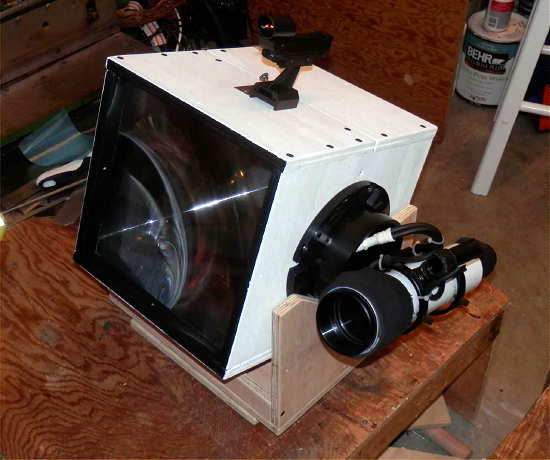
Except for the LED focusing sled, Toby's fine-looking transmitter box and LED driver / modulator, are now complete. The receiver is next on the list. I believe this will use one of the inexpensive ($5) fresnels lenses, purchased locally at Princess Auto, that seems to work very well for the price.
 |
| photos courtesy VE7CNF |
Clear Air Scatter Tests On 458THz
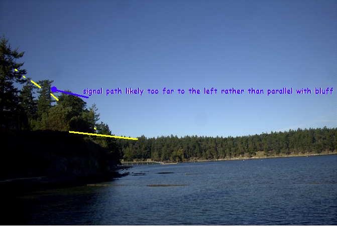
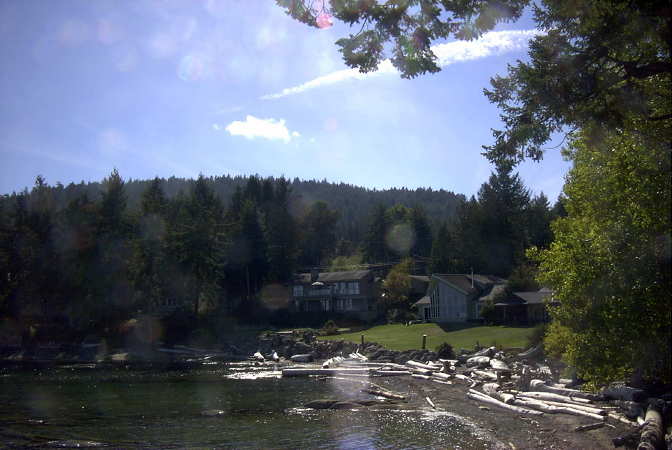
 After patiently waiting for the bright moon to clear the early evening skies, I was finally able to venture out for my first clear-air scatter test this past Sunday night. I had plotted the path on my Mayne Island map and determined bearings as best I could, but the path was going to be very tight. If the path plan was right, my signal should just clear the high beachfront bluffs at the chosen sea-level receiving site.
After carefully aiming the light, I set off for the receive site at around 7:45PM and was all set up with the new lightwave receiver about 30 minutes later. The site appeared fairly quiet and the Argo screen confirmed that there was little QRN coming from the local houses up on the bluff. I listened for over an hour, trying various slow changes in pointing ... varying the azimuth a few degrees at a time, and then the elevation. Unfortunately not the slightest indication of my ~549Hz tone was seen. I was confident that the system was working as several strobes were heard from distant aircraft (near Vancouver), as their flashing lamps skimmed the edge of the far treeline.

It seems likely that either my aiming or bearing calculations (or both) were off and that the signal was probably slightly to the west of me, with the bluff blocking any hope of reception ... I knew it was going to be close but was hoping for a little luck.
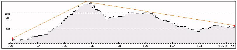
I left the transmitter outside overnight (it was set up two properties to the SE) and decided to try a second shot on Monday night. This path, although shorter by a mile, would require the signal to pass over two high hills ... the first topping out at 667' and the second at 567'. The overall direct-path distance was 1.7 miles (2.7 km). A cross-section of the signal path is shown below as it hugged the edges a little lower than the peaks:
 |
| courtesy: http://www.heywhatsthat.com/profiler.html |
I have been using a 'compass' app on my I-Pad to determine directions when aligning the transmitter and receiver setups. I'm not 100% convinced of its accuracy at all times, as readings can sometimes be a bit flaky. Before doing any more testing, I'll need to solve this, either with a better app or with a real compass.
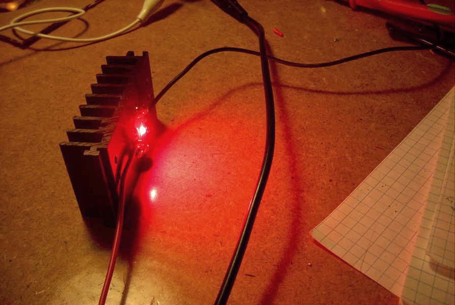
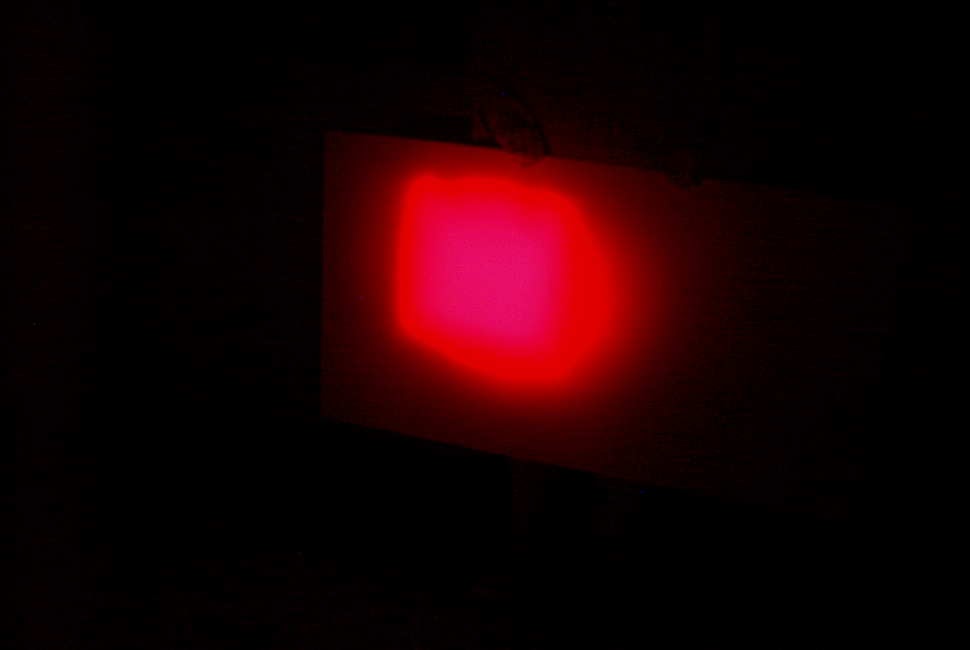
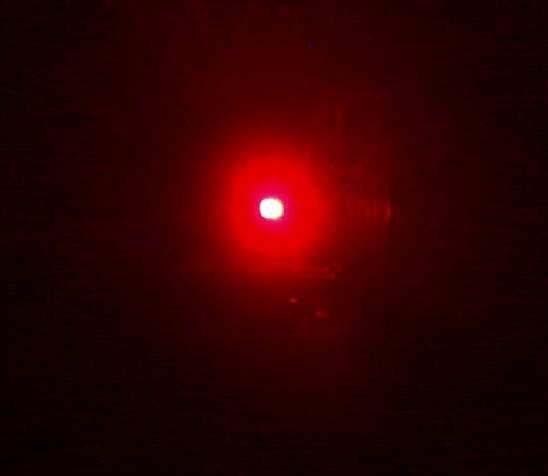
The transmitter was set up just before darkness, pointing right at the edge of the treeline along the 667' ridge and elevated at a 28 degree takeoff angle. The deep-red, 640mw LED, was switched-on just before departure at around 8:30PM.

It didn't take long to get set up in the back of the CRV, with the receiver temporarily set in no particular direction and plugged into the computer.
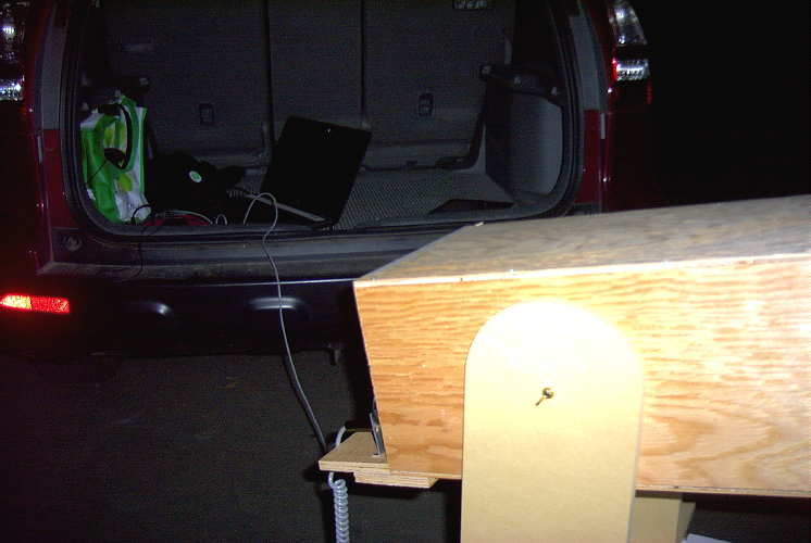
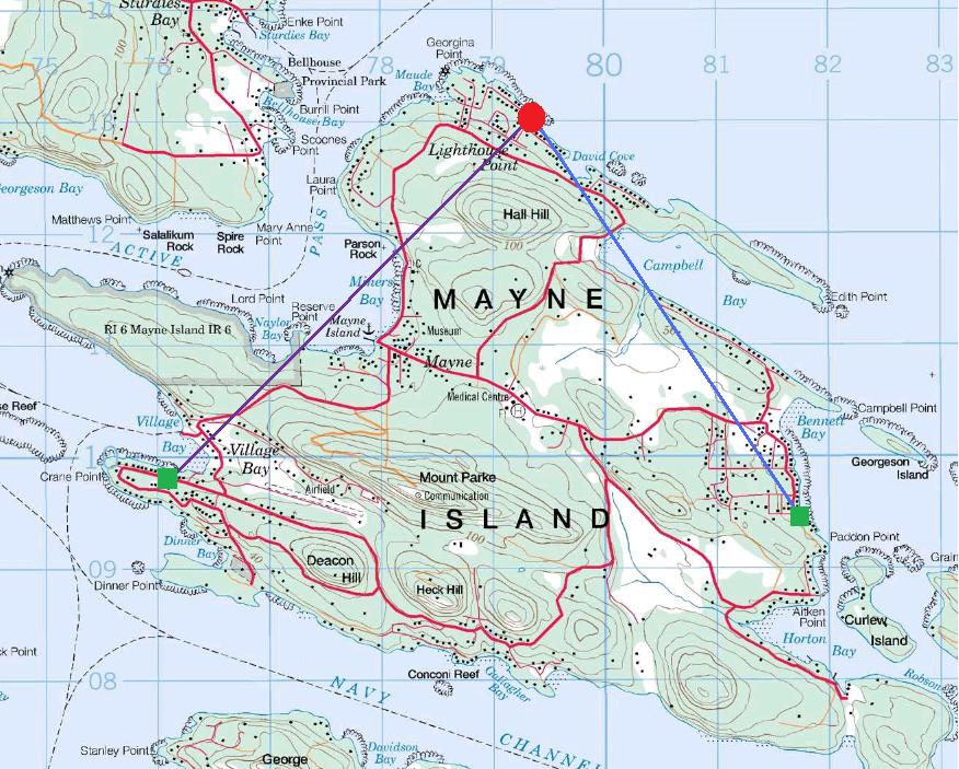
When Argo came to life, I went to the front of the car to grab the I-Pad so that the receiver could be aligned but was surprised to see a bright line at 549Hz when I came back! It seems that my 'rough' placement of the receiver was spot-on, and not exactly where I had originally intended. In fact, there appeared to be about a 10 degree error in where I had planned to point. I later traced the error to my path drawn on the paper map as it was difficult to determine my exact receiving location on the older map, which didn't show the new road where I had set up on.
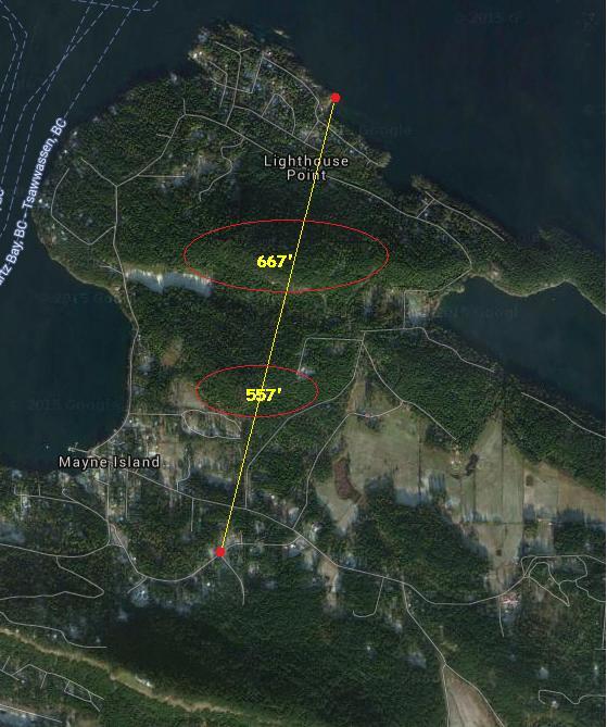 |
| Monday night's path |
With the strength of signals recovered on this path, two-way communication could have easily been established on any of the CW QRSS modes ... if quieter, probably on normal audible CW. Signal strength indicated that there was still plenty 'left in the bucket' for greater distance paths, probably much further than I am able to test here on the island.
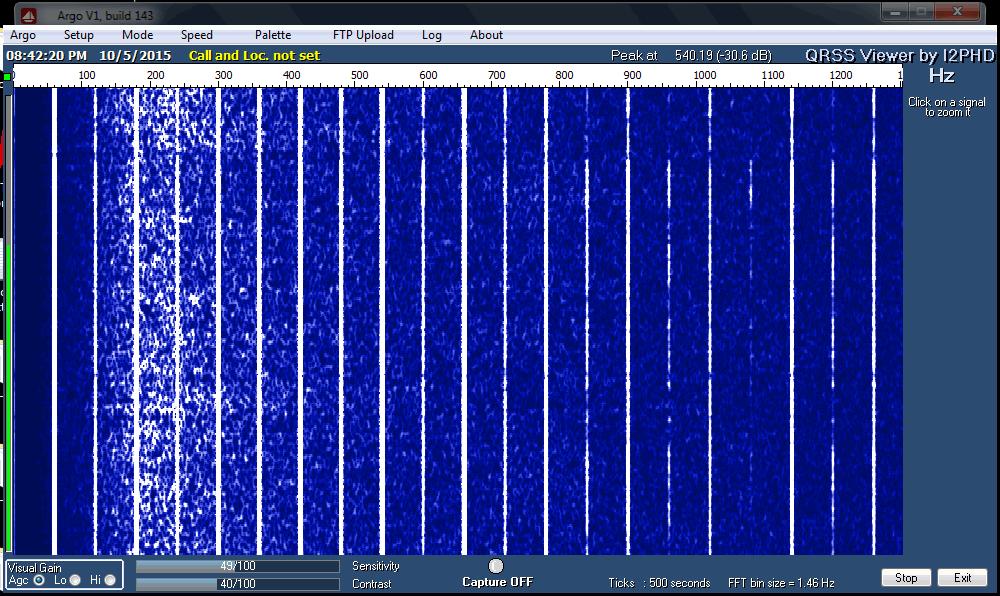
This was the first thing I saw, at the QRSS60 mode in Argo ... a fairly narrow passband and a ~25+ db dig into the noise.
Backing off to a wider bandpass (less sensitive) but faster QRSS10 mode showed the signal still very apparent:

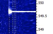
The almost 'real time' QRSS3 mode, although showing a much weaker signal, indicated that the signal would have been almost audible had it not been for the high level of background noise at this site. Don't confuse the lightwave signal with the much stronger 9th harmonic of 60Hz on 540Hz!
The ferry terminal was just down the hill about 1/2 mile and with several kilowatts of spectrum-polluting 60Hz sodium vapor lighting, the cloudy skies were a sea of bright-pink. There was a high level of audible hum in the phones, right from the start, that unfortunately, masked any hope of an audible detection. The waterfall screen capture shown below, illustrates the massive QRM at this otherwise nice site!
The night was not going to be complete without a strobe signature, captured on Argo from a high passing jet aircraft:
 | |
| strobes |
All-in-all, it was a very successful outing, considering the obstructed path and the $5 fresnel lens used in the portable receiver! I've examined the island map for any other possibilities and there are not many suitable candidates. I had hoped for one other possibility towards the west, which would stretch the path by almost another mile, but I'm not really sure that I can get a clear shot without hitting the very close treeline at this end.
I think the next round of testing will be in the other direction ... across Georgia Strait, with John, VE7BDQ, who has expressed interest in doing some deep overnight Argo searches for my signal in the clouds.
I'm not sure which mode would offer the best chance ... 'clear air scatter' or 'cloudbounce'. John has a very good receiver, with a slightly larger and better-quality fresnel than the one used in these tests. Working from his suburban backyard, directly across the strait at 13 miles (21 km) distant, his direct path to me is somewhat obstructed and will require an elevation angle of around 30 degrees at his end. I think, ideally, we would both like to be skimming just above the ocean, with only a slight elevation. A lower and less obstructed shot from his yard would mean an oblique path so this also remains a possibility. We will play with what we have and hope for the best ... even just a trace of signal would be a measured success.
I think that a non-line-of-sight (NLOS) contact would make an exciting challenge and a great project for two amateurs living in the same city or town, and ... you really don't even need a ticket!
For more technical details on the equipment used in this test, see "A West Coast Lightwave Project" describing the activities between here and Markus, VE7CA. We have just learned that this article will be published in the 2016 Radio Amateur's Handbook ... hopefully inspiring more new lightwave activity!
Lightwave Scatter Planning
Over the past few days I've been trying to figure out some possible pathways that might be covered when transmitting from home.
The only real directions that I can go any distances are towards the southwest and to the southeast because of two large hills (500' and 900') to the south.
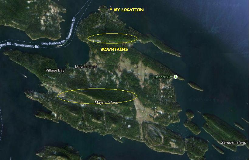 |
| courtesy: https://www.google.ca/maps |
 |
| courtesy: http://www.jeffstopos.com/ |
The challenge will be to put a signal over this 500' hill, about 1.5 km to the south ... I'll need to go around it on either side or over the top. Going around it at its edges will allow me to keep the light beam on a fairly low angle.
The main obstacle is my lot ... it is heavily treed in these directions and aiming would have to be too high of an angle to get over the trees. I do however, have one small gap between the trees which has turned out to be close to the right bearing (220 degrees) for the southwest test. For this, I can set the transmitter on my back sundeck and shoot through the gap without bothering anyone. For the southeast shot, or one over the top,of the hill, I'll need to move the transmitter two lots to the east of me, and use the neighbour's clear view of the hill.
This should work out OK, as the neighbour spends the winter in Boston and the house is vacant ... but the outside power sockets are alive. This path though, has me shooting across a small bay and above several houses. Most are summer residents only but there are a couple that are permanent. I'll need to contact them and give them a 'heads-up' before I run any tests, so they don't call the RCMP!
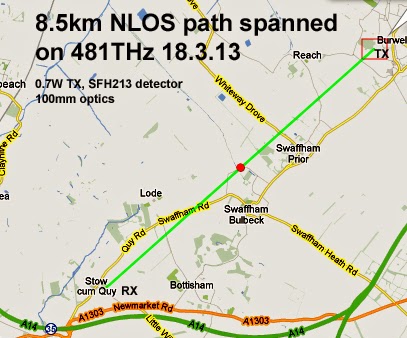
The June 2014 edition of Radcom has an inspiring article by G3XBM, "Over The Horizon At 481THz", where Roger describes his early clear air scatter tests and excellent results over an 8.5 km path. This is a very impressive distance considering the small LED transmitter and 4" magnifying-glass lenses used.
Unfortunately, the distances here, on both paths, are not very much ... about 5 km. I'm fairly limited to how far I can go here on the island. I'd be very happy to cover this comparatively short distance and a lot will depend on being able to keep a low enough angle and still get over the hill.
With the right weather, I may start as one reader has suggested, with a short almost vertical incidence shot and set up a few blocks away to test out the system.
Portable Lightwave Receiver Progress
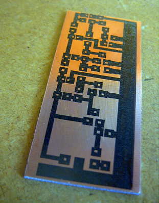
Yesterday, between dabbling in the Arkansas State QSO Party on CW, I manufactured and assembled the PCB for the new 'portable' lightwave receiver. When building PCBs, I use the printer-toner method, after drawing the design with MS Paint. Compared to some of the freeware PCB design software now available it is fairly crude, but it more than meets my needs and could even work for designing SMD boards if needed. I've also made the switch from using the messy and corrosive Ferric Chloride etchant to a weak solution of Hydrogen Peroxide and Muriatic acid. The latter seems so much cleaner, faster and overall produces a better-etched board. Boards can be completely etched in around three minutes, compared to the much longer Ferric Chloride.
I chose to use the same receiver circuit as the one in my main system, garnered from the design shown in Roger's, (G3XBM) blog. If you have an interest in getting started in lightwave experimenting, you will find Roger's blog of his lightwave adventures to be both informative and inspiring.
 |
| courtesy: http://g3xbm-qrp.blogspot.ca |
As before, I made a couple of minor changes to the receiver, substituting a BPW34 optical pin diode for the one shown as well as subbing a 2N5457 JFET for the MPF102. In addition, 2N5089s were substituted for the 2N3904s. The newer JFET is lower in noise as are the higher gain 5089s. In all likelihood, the differences are only minor but I like to think that every little bit helps when all system-losses are considered.
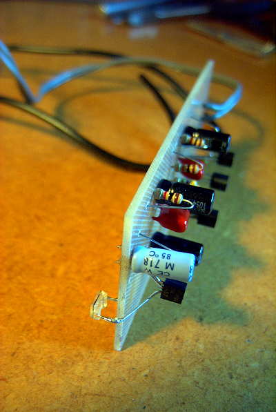
Note that it is important to make the connection between the diode and the JFET's gate lead 'floating' in the air as any contact with the PCB could introduce unwanted loses at this point.
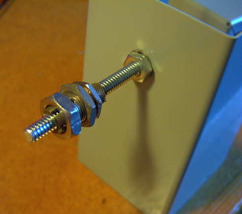
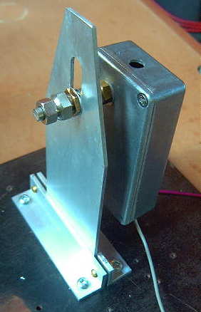
As in my original receiver, a locking split-shaft, removed from a junk box potentiometer, was mounted to the back side of receiver box. This will allow the receiver box and its pin-diode to be aligned forward and backward for focus and then locked. Once built, the focusing carriage will allow the receiver to move laterally, left to right as well as vertically, up and down. Positioning the optical diode at the exact focal point of the lens and maintaining this position is crucial. The finished carriage, will look similar to this one, used in my main system's receiver and transmitter box.
So it's on to the plywood receiver box and then the focusing carriage. It will be interesting to see how my $5 fresnel lens page-reader, purchased from Princess Auto, compares with the slightly larger (and probably better) lens in the main system's receiver.
Optical communications over the horizon
I have been too unwell to do this recently, but not long before my brain bleed (Sept 2013) I was amazed at optical communications over the horizon, non line of sight (NLOS) using clear air scattering.
The inspiration for all my optical experiments came from Stuart Wisher G8CYW who did a great series in RadCom a few years ago.
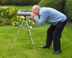 | |
| Testing optics |
My home made transmitter only consumed about 0.7W from a red LED bought on the internet. My homemade RX and TX used homemade optics based around cheap drain pipes and cheap magnifying glasses. The whole RX and TX were simple and low cost. Only simple test gear was needed too. It is a bit like microwaves, but easier to build and test.
There was no sign at all of the TX beam in the sky. All alignment used dead reckoning with some panning at the RX end to find the TX.
Using free PC software and QRSS3 helped as bandwidths as low as 0.37Hz were possible.
When fitter I want to try infra-red LEDs instead.
See https://sites.google.com/site/g3xbmqrp3/optical/481thz-nlos.
Optical testing – too easy?
Before dark, I tried TXing from one side of the house to the other reflecting my 481THz optical beacon off the windmill. Even by ear in 600 ohm phones the signal was very clear and very easy to find. This was only about 100m path length, but I wanted to check the gear still worked as it is a long time since I used it. Not sure what to try next as I still feel very wobbly on my feet and tire easily. At least I know my homebrew optical gear all works still.
Next field test – optical?
After my very disappointing results on VLF earth-mode yesterday – I must get to the bottom of why results were quite so bad – I think my next test will be at the other end of the spectrum. We have a windmill very close so I may try bouncing optical signals off this to test my optical gear is working still. It is a long time since I have done any optical experiments.This will not be too far initially, more a test of the gear before venturing any distance.


