 |
 Portable Lightwave Receiver Progress
Yesterday, between dabbling in the Arkansas State QSO Party on CW, I manufactured and assembled the PCB for the new 'portable' lightwave receiver. When building PCBs, I use the printer-toner method, after drawing the design with MS Paint. Compared to some of the freeware PCB design software now available it is fairly crude, but it more than meets my needs and could even work for designing SMD boards if needed. I've also made the switch from using the messy and corrosive Ferric Chloride etchant to a weak solution of Hydrogen Peroxide and Muriatic acid. The latter seems so much cleaner, faster and overall produces a better-etched board. Boards can be completely etched in around three minutes, compared to the much longer Ferric Chloride.
I chose to use the same receiver circuit as the one in my main system, garnered from the design shown in Roger's, (G3XBM) blog. If you have an interest in getting started in lightwave experimenting, you will find Roger's blog of his lightwave adventures to be both informative and inspiring.
 |
| courtesy: http://g3xbm-qrp.blogspot.ca |
As before, I made a couple of minor changes to the receiver, substituting a BPW34 optical pin diode for the one shown as well as subbing a 2N5457 JFET for the MPF102. In addition, 2N5089s were substituted for the 2N3904s. The newer JFET is lower in noise as are the higher gain 5089s. In all likelihood, the differences are only minor but I like to think that every little bit helps when all system-losses are considered.
Note that it is important to make the connection between the diode and the JFET's gate lead 'floating' in the air as any contact with the PCB could introduce unwanted loses at this point.
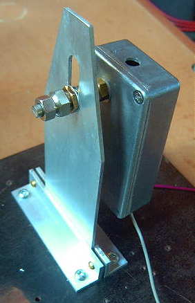
As in my original receiver, a locking split-shaft, removed from a junk box potentiometer, was mounted to the back side of receiver box. This will allow the receiver box and its pin-diode to be aligned forward and backward for focus and then locked. Once built, the focusing carriage will allow the receiver to move laterally, left to right as well as vertically, up and down. Positioning the optical diode at the exact focal point of the lens and maintaining this position is crucial. The finished carriage, will look similar to this one, used in my main system's receiver and transmitter box.
So it's on to the plywood receiver box and then the focusing carriage. It will be interesting to see how my $5 fresnel lens page-reader, purchased from Princess Auto, compares with the slightly larger (and probably better) lens in the main system's receiver.
2 Responses to “Portable Lightwave Receiver Progress”
Please support our generous sponsors who make AmateurRadio.com possible:
 Ham Radio Deluxe |
 W5SWL Electronics |
 Ham Radio Prep |
 KB3IFH QSL Cards  Hip Ham Shirts  HamRadioAuctions HamRadioAuctions Reliance Antennas Reliance Antennas Enigma Shop Enigma Shop |  morseDX  Ni4L Antennas  R&L Electronics R&L Electronics antennas.us antennas.us QRV QRV |
- Matt W1MST, Managing Editor

Thanks for the mention of my blog again Steve and very best of luck with lightwaves. It has rather had to take a back seat with my poor health of late but I hope to get back to NLOS optical again before too long.
Thank you Roger! I wish we lived closer as I’m sure we could stir up a lot of lightwave mischief between the two of us. Hope your back at it soon so we can compare notes.
73