Posts Tagged ‘nanowave’
 VE7CNF’s Lightwave Cloubounce / Scatter Tests
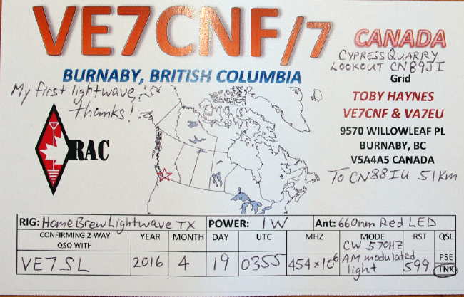
After our recent lightwave CW QSO, described here, Toby (VE7CNF) has been re-focusing on refining his lightwave system for weak signal non-line-of-sight (NLOS) cloudbounce and scatter mode experiments.
His testing to date has been limited to within his own suburban yard, with the transmitter being set up on the south side of the house and the receiver set up on the north, while basically pointing things straight up.
Several tests have already been done with exciting results, including audible CW being returned from a low (5,000') cloud ceiling and weaker returns noted on clear air scatter but readily detected in the CW QRSS mode. Toby has also interfaced his PC audio, via amplifier and FET driver, to enable him to use WSPR and JT9 modes, resulting in positive signal returns using these two digital modes of modulation.
Toby described some of his results and methodology in a recent e-mail updater:
I've done some lightwave backscatter experiments this last week. The transmitter is on my front deck, pointed straight up as verified using a level across the lens end of the box. The receiver is in the back yard and pointed up also. Between the two, the house is about 30ft high and blocks any direct light.
Last night May 8 UTC was clear and I was getting a QRSS10 level signal with the receiver pointed at elevations from 70 to 85 degrees, through the transmitter beam. There was nothing received from straight up, so the clouds were too high for cloud backscatter. At 80 degrees elevation I got the best signal. I've attached an Argo screen grab of QRSS10 (FSK CW with the 570 Hz tone as key-down).
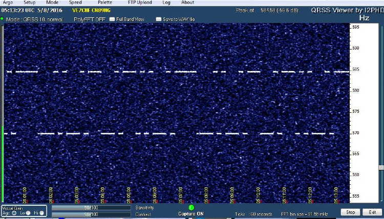 |
| QRSS10 CW clear air scatter return signal |
WSPR2 was decoding consistently and JT9 was about 70%. I tried JT65, BPSK31, and MFSK8 but the SNR was too low for those to work.
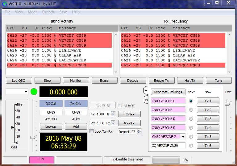 |
| JT9 cloudbounce return signal 14,000 - 24,000 FT |
May 8, 2016 UTC CYVR clouds and temperature/dewpoint data:
0500 FEW CLOUDS (1/8 - 2/8) 14000 FT, SCATTERED CLOUDS (3/8 - 4/8) 24000 FT, 14 C / 11 C
0600 FEW CLOUDS (1/8 - 2/8) 14000 FT, SCATTERED CLOUDS (3/8 - 4/8) 24000 FT, 14 C / 9 C
0700 FEW CLOUDS (1/8 - 2/8) 12000 FT, FEW CLOUDS (1/8 - 2/8) 22000 FT, 13 C / 7 C
... I'll try CW and digital again when there's some lower cloud conditions. That’s tough to get without rain at the same time.
I did get dew on the receiver last night, so I'll be adding heating resistors inside the boxes to keep the lenses warm. Electric heating has worked great to keep dew off the optical surfaces of my telescope. I'll also look at adding shrouds to shield the lenses from the cold sky.
More from May 15th:
Last night was good for backscatter from low clouds, at 1300 to 1900 ft according to airport weather. I had to stay up late though, as the cloud didn't move in until midnight.
I've attached a couple of CW recordings. Early on the signal was weaker with QSB. Later it was strong and solid.
I've also attached a screen grab of WSPR2. Signals were up around 0dB this time.
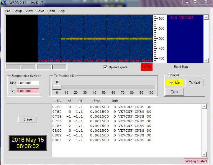 |
| WSPR cloudbounce return signals 1300 - 1900 FT |
I played with a bunch of digital modes and FMHELL and SSTV. Everything was working pretty well off the clouds.
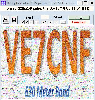 |
| SSTV cloudbounce return signal |
The nextstep is to move the rx farther from home, then to try sending signals over to John or Steve by cloud bounce.
Toby's nearest lightwave neighbour, VA7MM, is in mid-build and is working to complete a system capable of running overnight cloudbounce / scatter tests between their two respective backyards ... the NLOS distance is about 15 km. Although the path includes some bright commercial lighting QRM, with narrow-band modes such as QRSS or WSPR, it may not be a problem. I suspect one of the biggest problems will be getting suitable weather as, here on the west coast, dense clouds usually turn into rain very quickly, especially near the coastal mountains where Toby and Mark are located.
I find Toby's results to be both encouraging and exciting! It will be interesting to try some cloudbounce between their respective stations and my own and maybe hopping the NLOS path across cloudy Georgia Strait. It may well be possible to do this in one of the quicker QRSS CW modes such as QRSS3 or QRSS10, both of which can have fairly fast exchanges of the required information (calls, signal report and final confirmations). Failing that, slower QRSS30 or one of the weak signal digital modes such as JT9 / WSPR which have the ability to dig deep (-30db) into the background noise may be the answer ... there is much to learn yet!
Clear Air Scatter Tests On 458THz
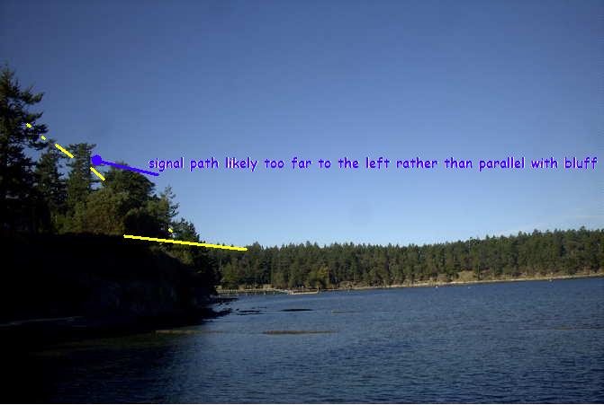
 After patiently waiting for the bright moon to clear the early evening skies, I was finally able to venture out for my first clear-air scatter test this past Sunday night. I had plotted the path on my Mayne Island map and determined bearings as best I could, but the path was going to be very tight. If the path plan was right, my signal should just clear the high beachfront bluffs at the chosen sea-level receiving site.
After carefully aiming the light, I set off for the receive site at around 7:45PM and was all set up with the new lightwave receiver about 30 minutes later. The site appeared fairly quiet and the Argo screen confirmed that there was little QRN coming from the local houses up on the bluff. I listened for over an hour, trying various slow changes in pointing ... varying the azimuth a few degrees at a time, and then the elevation. Unfortunately not the slightest indication of my ~549Hz tone was seen. I was confident that the system was working as several strobes were heard from distant aircraft (near Vancouver), as their flashing lamps skimmed the edge of the far treeline.

It seems likely that either my aiming or bearing calculations (or both) were off and that the signal was probably slightly to the west of me, with the bluff blocking any hope of reception ... I knew it was going to be close but was hoping for a little luck.
I left the transmitter outside overnight (it was set up two properties to the SE) and decided to try a second shot on Monday night. This path, although shorter by a mile, would require the signal to pass over two high hills ... the first topping out at 667' and the second at 567'. The overall direct-path distance was 1.7 miles (2.7 km). A cross-section of the signal path is shown below as it hugged the edges a little lower than the peaks:
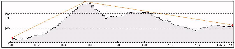 |
| courtesy: http://www.heywhatsthat.com/profiler.html |
I have been using a 'compass' app on my I-Pad to determine directions when aligning the transmitter and receiver setups. I'm not 100% convinced of its accuracy at all times, as readings can sometimes be a bit flaky. Before doing any more testing, I'll need to solve this, either with a better app or with a real compass.
The transmitter was set up just before darkness, pointing right at the edge of the treeline along the 667' ridge and elevated at a 28 degree takeoff angle. The deep-red, 640mw LED, was switched-on just before departure at around 8:30PM.

It didn't take long to get set up in the back of the CRV, with the receiver temporarily set in no particular direction and plugged into the computer.
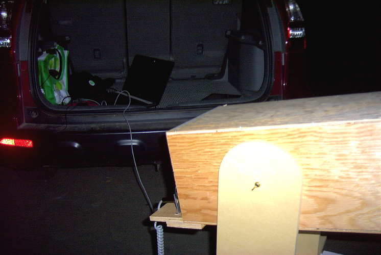
When Argo came to life, I went to the front of the car to grab the I-Pad so that the receiver could be aligned but was surprised to see a bright line at 549Hz when I came back! It seems that my 'rough' placement of the receiver was spot-on, and not exactly where I had originally intended. In fact, there appeared to be about a 10 degree error in where I had planned to point. I later traced the error to my path drawn on the paper map as it was difficult to determine my exact receiving location on the older map, which didn't show the new road where I had set up on.
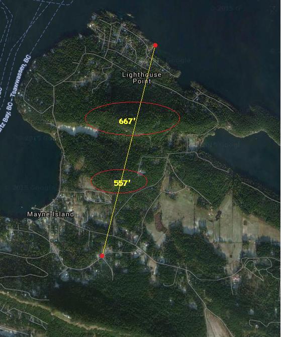 |
| Monday night's path |
With the strength of signals recovered on this path, two-way communication could have easily been established on any of the CW QRSS modes ... if quieter, probably on normal audible CW. Signal strength indicated that there was still plenty 'left in the bucket' for greater distance paths, probably much further than I am able to test here on the island.
This was the first thing I saw, at the QRSS60 mode in Argo ... a fairly narrow passband and a ~25+ db dig into the noise.
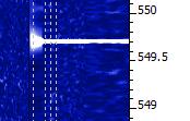
Backing off to a wider bandpass (less sensitive) but faster QRSS10 mode showed the signal still very apparent:

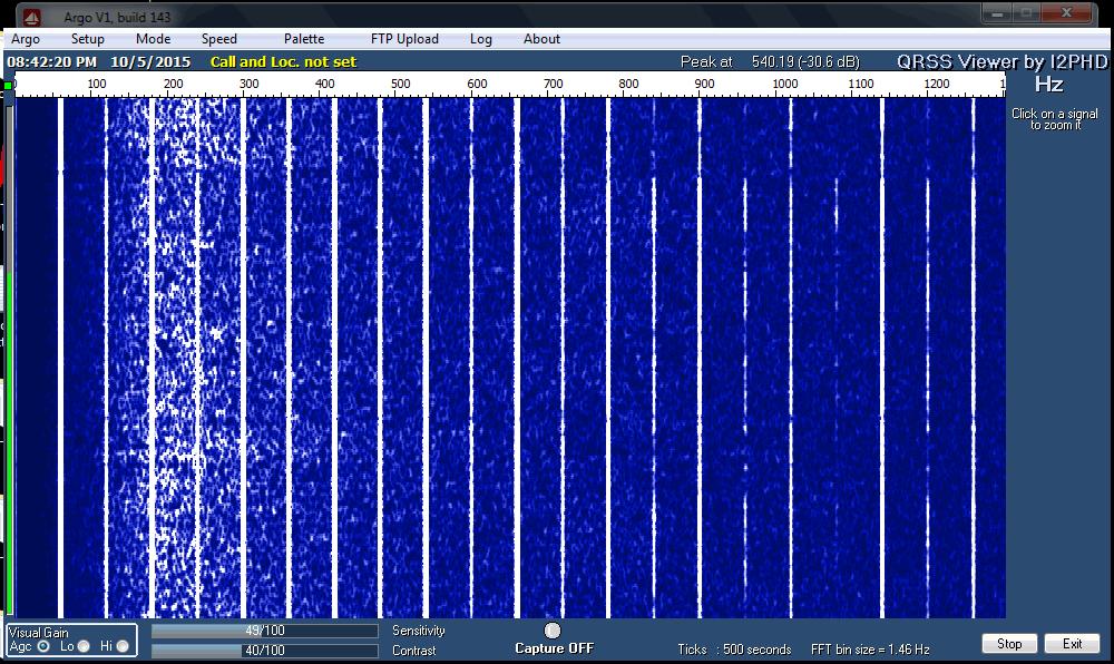
The almost 'real time' QRSS3 mode, although showing a much weaker signal, indicated that the signal would have been almost audible had it not been for the high level of background noise at this site. Don't confuse the lightwave signal with the much stronger 9th harmonic of 60Hz on 540Hz!
The ferry terminal was just down the hill about 1/2 mile and with several kilowatts of spectrum-polluting 60Hz sodium vapor lighting, the cloudy skies were a sea of bright-pink. There was a high level of audible hum in the phones, right from the start, that unfortunately, masked any hope of an audible detection. The waterfall screen capture shown below, illustrates the massive QRM at this otherwise nice site!
The night was not going to be complete without a strobe signature, captured on Argo from a high passing jet aircraft:
 | |
| strobes |
All-in-all, it was a very successful outing, considering the obstructed path and the $5 fresnel lens used in the portable receiver! I've examined the island map for any other possibilities and there are not many suitable candidates. I had hoped for one other possibility towards the west, which would stretch the path by almost another mile, but I'm not really sure that I can get a clear shot without hitting the very close treeline at this end.
I think the next round of testing will be in the other direction ... across Georgia Strait, with John, VE7BDQ, who has expressed interest in doing some deep overnight Argo searches for my signal in the clouds.
I'm not sure which mode would offer the best chance ... 'clear air scatter' or 'cloudbounce'. John has a very good receiver, with a slightly larger and better-quality fresnel than the one used in these tests. Working from his suburban backyard, directly across the strait at 13 miles (21 km) distant, his direct path to me is somewhat obstructed and will require an elevation angle of around 30 degrees at his end. I think, ideally, we would both like to be skimming just above the ocean, with only a slight elevation. A lower and less obstructed shot from his yard would mean an oblique path so this also remains a possibility. We will play with what we have and hope for the best ... even just a trace of signal would be a measured success.
I think that a non-line-of-sight (NLOS) contact would make an exciting challenge and a great project for two amateurs living in the same city or town, and ... you really don't even need a ticket!
For more technical details on the equipment used in this test, see "A West Coast Lightwave Project" describing the activities between here and Markus, VE7CA. We have just learned that this article will be published in the 2016 Radio Amateur's Handbook ... hopefully inspiring more new lightwave activity!
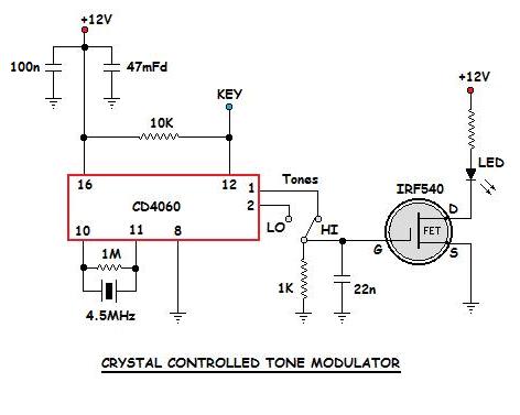
New Lightwave Modulator
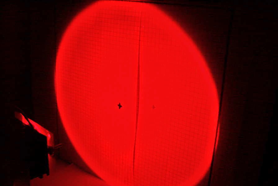 Yesterday I completed the construction of the crystal-controlled tone generator which will be used to modulate my lightwave transmitter during future clear-air / cloudbounce tests.
 It was installed on the lightbox, right beside the original 556 CW beacon / tone generator.


The crystal-controlled oscillator uses a CD4060 IC as an oscillator-divider and produces a ~550Hz or a ~1098Hz squarewave from the 4.5MHz crystal.
 |
| 4500KHz xtal divided by 8192 showing 549Hz output |
As can be seen by comparing the two oscillators (crystal on the left and 556 on the right), the 556 has a lot of drift (although it looks like it might eventually stabilize) and, as well, produces several spurious signals ... probably robbing power from the main tone. The crystal-controlled signal is rock solid and doesn't appear to generate any parasitic signals in the process. The trace below the crystal signal is unrelated to the oscillator.
When I first wired the unit up, I found an unstable low frequency oscillation from the 4060 during key-up conditions, due no doubt, to the lengthy leads inside the box. This was cured by adding a pull-up resistor to the keying line as shown in the final schematic below.
Now it's on to building another fresnel-lens receiver box which will be needed for any field work here on the island.
ET Call Home

Late last week I received an interesting e-mail from Thomas Pell in Winter Haven, Florida.
It seems that Tom has been doing some building after reading my series of blogs about my lightwave adventures and has started his own adventure. As he told me initially:
"... I'm retired with too much time on my hands, and I'm tired of the big gritty hobby projects ... after reading about Harvard U's optical SETI project, which looks for extraterrestrial laser signals with a 48 inch, then 72 inch mirror. I thought it would be fun to build a setup like theirs, but at audio frequencies instead of the RF laser signals ... my purpose was to get light signals from other amateur laser dx experimenters or even ET ... better than watching my wife's TV shows. Also a giant telescope that costs almost nothing is fun too."
Tom built up the PIN diode detector shown in my notes, which was a slight variation of the one developed by Roger, G3XBM (see his great lightwave notes here) and based on an earlier plan by K3PGP.
Along with the receiver, Tom built a substantial optical antenna ... a 48" Mylar-based parabolic mirror!
"... it is a wood structure ... round piece of 1/2 inch plywood, 48" in diameter ... around the perimeter a 4" wide strip of 1/8" plywood is wrapped and glued with epoxy putty. On the upper end of 1/8 ply is another circular plywood flange inside. This flange is to glue mylar sheet. The mylar is then tensioned with tape on the side. It is something like a round guitar in appearance... a box ... you suck the air out ... I use a shop vacuum with 1/4 in rubber tube taped to vacuum hose ... hose barb epoxied to hole inside of mirror ... not ideal but if you seal it up well with epoxy, it works..."
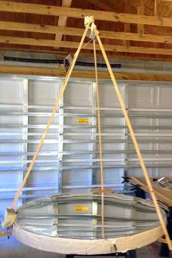 |
| courtesy: Thomas Pell |
It seems that there is now an active movement amongst some SETI enthusiasts to search for optical beacons rather than radio beacons. When you think about it, it would seem to make just as much sense, if not more, to beacon with a modulated optical signal than with a radio signal ... and the optical signal might be far easier to detect. Some of the papers suggest that an optimum frequency would be in the near IR or deep red part of the spectrum, right where most optical amateur two-way work is presently being done.
During his first few tests of the new mirror, Thomas stumbled upon one signal (the only one) which came from just one single point in the sky ... almost directly overhead in Orion.
"At 9:30 pm 3/5/2015, using the amplifier circuit you use in your optical communication receiver connected to a 48 inch parabolic mirror, I received an apparently modulated optical signal originating in center of Orion constellation. Signal was audio frequency low to high pitch and lasted for more than an hour. I located the signal by moving the mirror back and forth across the sky for nearly an hour until I found a "blip", then focused the mirror exactly on the spot to listen to it, incredible experience."
"Received signal again last night from same location. I am becoming convinced it is information of some kind.Very irregular rapidly pulsed. This was only a test of amplifier ... I never expected this result, was totally unprepared. Meanwhile time is passing and I can't seem to contact anyone to have it confirmed before it disappears from the sky. It seems, no one has a setup like this ... this signal is either very important or it's nothing ... I think. Will let you know about outcome."
At this point, Tom is just trying to figure out what type of signal he has been hearing and will be attempting to get a better recording of it over the next few nights. I have heard his initial recording, just done with an I-pad held close to the amplifier's speaker output and it does sound suspiciously like a data train of clicking pulses. Hopefully Tom will solve the mystery soon!
Measuring The New Lenses

Yesterday I had the chance to have a closer look at the two lenses recently purchased for a new portable lightwave receiver. The initial testing procedure of the page-size fresnel (actual size is 200mm x 270mm) proved incorrect and required more space than the bench top could provide. Eventually the focal length was measured as ~ 368mm +/- for an f/d, or F number, of 1.36 ... a convenient value and much better than the 'other' common fresnel page reader focal length of ~ 600mm. This jibed nicely with the recommendations given in Clint's (KA7OEI) website optical information:
"For practical reasons, it is recommended that an optical system using Fresnel lenses be designed using lenses that have an F-number in the range of 0.5 to 1.5 - that is, around 1. Remember: The "F-number" is the focal length divided by the diameter of the lens, so for an F-number of unity or one, the diameter of the lens would be the same as its focal length."
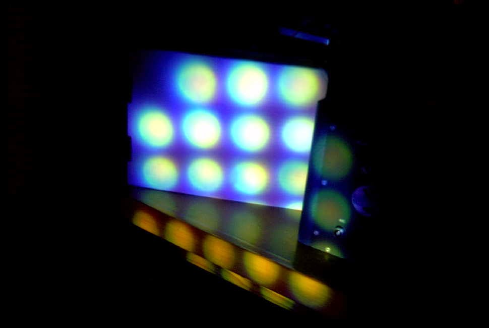
The lens was able to bring a small LED flashlight (consisting of an array of 21 white LEDs) into surprisingly sharp focus although the shot below does not reflect that due to my camera's poor focus in the darkened room.
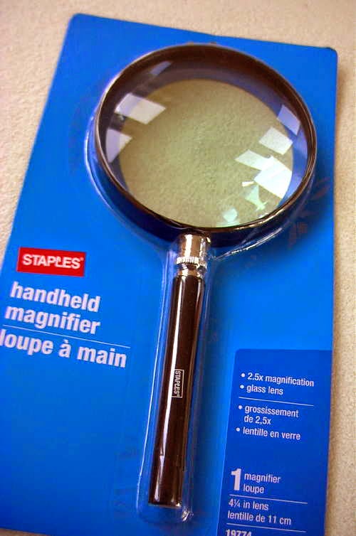
The glass 4.5" magnifying lens proved to have a focal point of 203mm for an F number of 1.8. This lense produced an even sharper image of the same light source and may be the best candidate for the portable receiver although the larger aperture of the fresnel might not be worth counting out at this point.
The fresnel may work well for a transmitter and will likely require a small (inexpensive) secondary focusing lens between the LED and the fresnel, in order to have the LED efficiently illuminate the fresnel. The secondary should effectively gather and focus as much of the emitted LED light to just within the boundaries of the fresnel without any wasted light energy being lost to spill-over at the edges.
It would be great to have a permanent lightwave 'beacon' that one could test various receiver lenses and combinations but at present there is very little activity here in VE7 land ... although that is changing, with the interest of another local, VE7IGH (Greg) near Vancouver and right across Georgia Strait from my location. Grant has already built a receiver and will soon start on transmitter construction ... way to go Greg!
’29 MOPA / NLOS Lightwave Progress
 |
| Courtesy: http://www.arrl.org/ |
I've now completed a set of tank coils for the new'29 MOPA project. These were wound with 3/16" copper tubing which has become very difficult to source. Luckily, after much searching, I was fortunate enough to find several rolls locally at a very attractive price. Although I do see it quite often on e-bay, sellers either refuse to ship to Canada or their shipping charges are far too high to make it worthwhile. The larger 1/4" rolls are still readily available, but for any given inductance, will take up a lot more room on the breadboard if space is an issue.
These coils cover the amplifier tank, the Hartley oscillator's tank, and the antenna coupling link. Respectively, the coils measure 4.9uH, 4.0uH and 1.9uH.
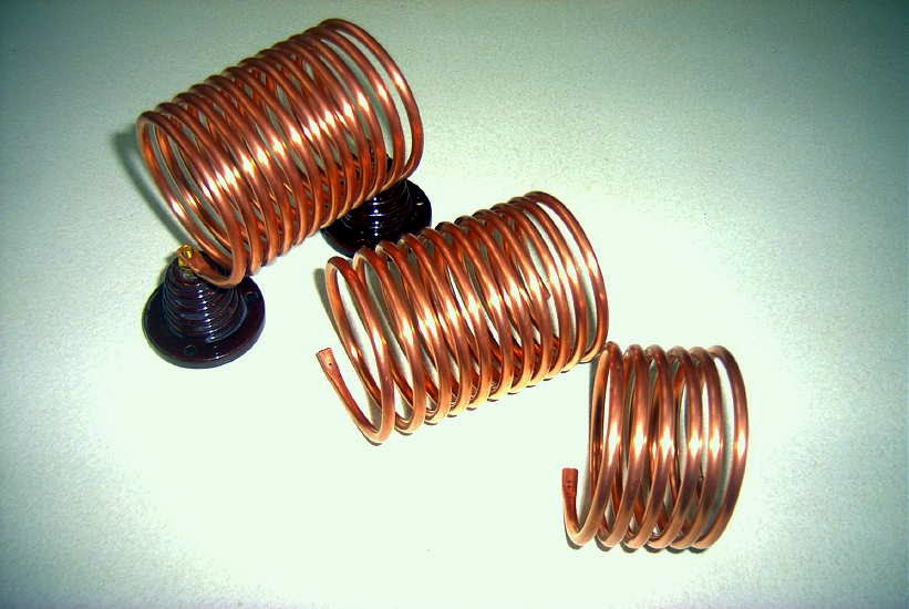
Winding these is always fun but the method used requires that the needed length be predetermined and cut from the roll beforehand. The first time I did this, when building my TNT transmitter, I learned the hard way to always add at least another foot to cover the additional length eaten-up by turn-spacing and for coil end flattening and mounting.
While visiting Vancouver for a few days I was able to find a couple of pieces needed for my non-line of sight (NLOS) lightwave experiments.
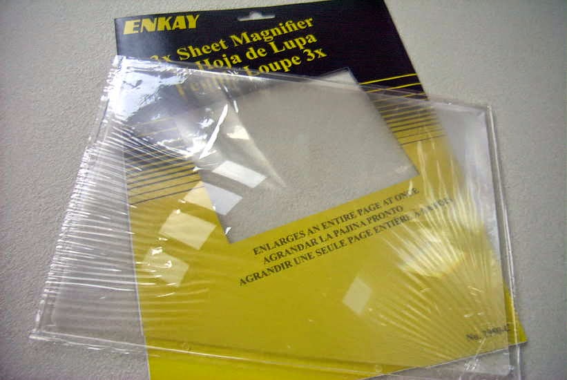
I purchased a nice 4.25" magnifier lens, with suitable focal length, as well as an inexpensive page-size fresnel magnifying lens. What is particularly pleasing is that the fresnel is a rigid lens, about 2 mm thick, unlike most page magnifiers that are thin and floppy. I have yet to test its blur circle or determine its focal length.
I plan to use one or the other of these lenses in a small, portable lightwave receiver module that I can carry to the other side of the island to listen for the main large transmitter, aimed slightly above the horizon, in beacon-mode. If the smaller fresnel does the job, it will be an inexpensive source for anyone else needing a simple lens for either transmitting or receiving.
If the deep-red light tests prove successful, I'll switch the system to IR light but at this stage I'm not sure how focusing and optimizing receivers and transmitters can be done with a light source that is essentially invisible? Perhaps using an IR source that is right on the edge of deep-red will still have enough visible light to allow finding the optimum focus more easily.
More information on NLOS experiments can be found in Yahoo's Optical DX Group as well is in G3XBM' s 481thz blogs.
As well, anyone in the Vancouver lower mainland (as far as the northern Sunshine Coast area) that might be considering lightwave ... I'd love to work you! Pretty well any high spot in this region is direct LOS for me.
Lightwave Article From ‘TCA’
 |
| VE7SL Backyard Test |


