Posts Tagged ‘nanowave’
 VK4EBP’s NLOS Lightwave Experiments – Part 3
 |
| F1AVY's Cloudbounce System |
"Returning to Steve's questions and our general discourse:
..is it (the RX) fairly small and portable...and lensless?
I do have a lens in the RX I now prefer to use - although it happens to be a convex lens from a tabletop magnifier - about 7x12cm giving me a narrow reception beam and a fair bit of gain compared with naked photodiode. There seems to be a general agreement that increasing the size of receiving aperture will capture more light and is the best way to greater gain.
Here I need to qualify gain requirements for my particular applications. I am currently exploring relatively short-distance NLOS paths in urban environments with abundant QRM from city and suburban lights, and this already limits my gain requirements. I developed my own qualitative test of satisfactory sensitivity - by pointing my receiver at individual stars in the sky. If I can hear them twinkle (yes they do twinkle!!!) then I am generally satisfied with the project.
On cloudy nights, pointing the RX into the clouds brings an interesting combination of mains harmonics and general hash from neon lights, clicking pulses from aeroplane lights, sweeping sounds from airport and marine lighthouses. In an environment like this, going to extreme lengths as one would do for very long-range cloudbounce or LOS comms in dark and secluded areas is simply not required and uneconomical. I initially did invest time and money in large receiving boxes with the best components there are, only to find that, unless I moved out into the bush, I could not take a real advantage of the improved performance, and did equally well with smaller and more wieldy portable designs.
"Is the idea, when talking about NLOS, to light up as much sky as possible...and that is why no focusing lenses are employed? Would a focused emitter, as produced by the typical Fresnel lens light box, produce too narrow a beam than desired? It would seem likely that with precise aiming combined with the gain to be had by utilizing fresnels (for example), would produce longer paths??"
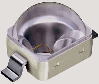
There are several separate issues there. One is the implied requirement for a large Fresnel lens in order to obtain a narrow beam. First, how narrow is narrow enough? If we can be satisfied with say +- 5 degrees then there are more wieldy solutions available - most of the high power LEDs now have clip-on small spot lenses awailable separately - usually from third-party manufacturers. These were unheard of until recently. Standard-sized LEDs are available with very narrow radiation pattern, e.g. the SFH4550 at barely +-3 degrees. And one would expect an array of 200+ of them to behave quite like our stacked Yagis, many times over! Hence narrow beam is quite possible even without an external lens.
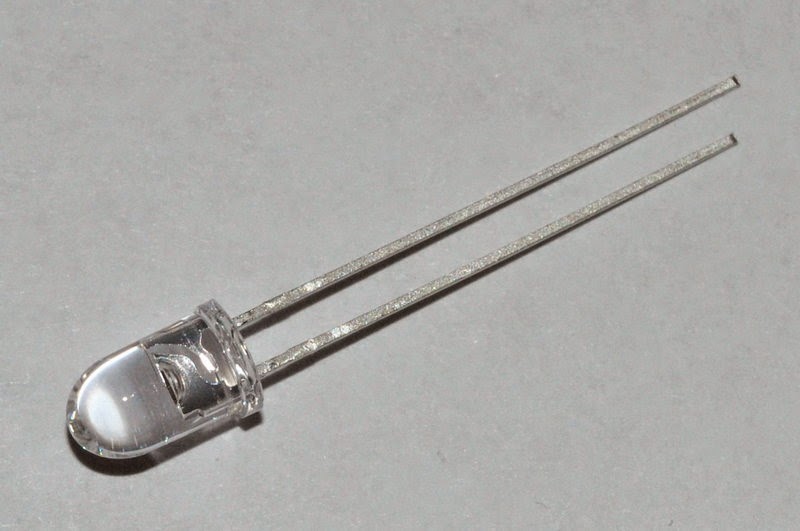 |
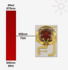
| Osram SFH4550 IR LED |
Of course the extremely narrow beams that one would prefer for LOS DX comms would be next to impossible to align in NLOS situation. (Invisible infrared is not a problem in LOS as it can be easily supplemented with e.g. a plain strobe light for alignment purposes.) I find my +-3 degrees array (with similar +-3 deg aperture at receiving end) hard enough to align over the horizon, and it is probably the limit of how narrow one can go to remain practicable in NLOS.
"to light up as much sky as possible..."
It is possible that cloudbounce and obstruction-bounce will develop into separate NLOS techniques, along with atmospheric scatter. Of course one can think of all of these in some topographies.
I had some success in inter-suburban cloudbounce with high beam elevations at both ends - 30 to 60 degrees. Also with 45 degrees or less elevation with TX and RX about 1km apart side by side and pointing at the same cloud in the distance. Power used around 10-20W, beamwidth +-5 to 10 degrees, red and infrared with similar results (including 950nm). The received signal was just strong enough for telegraphy or qrss, but never near enough for any type of voice modulation. Results were affected by the height of cloud cover necessitating frequent elevation adjustment, and an additional liaison channel on VHF. Signals disappeared entirely as soon as the clouds started producing rain.
I never got any usable results with clear night sky and the TX and (imaginary) RX beams crossing each other at similar elevations. Only at very close distances - the best signals being received with blue and infrared. Presumably Rayleigh scatter with blue. (This raises the possibility of usable atmospheric scatter with UV?)
Only recently I commenced preliminary tests with close-to-ground, low-elevation NLOS and immediately the infrared proved itself to be a clear winner with quite reliable and repetitive results. (Needless to say the signal strengths are marginal compared with direct LOS over similar distance.) Intuitively, one would suspect general scatter and bouncing of nearby objects being the main sources of some of the energy reaching over the horizon, with some contribution perhaps of atmospheric/dust/aerosol scatter.
This adds an additional dimension to your question.. to light up as many objects around the TX(or around RX, or around the obstruction) as possible, or send the focused beam as far as possible? I guess it will very much depend on topography. I can imagine a situation where I would prefer to use a broad floodlight rather than a focused beam - e.g. to illuminate as many as possible of the surrounding tall buildings if transmitting from a ground floor apartment. Or from the foot of a mountain. An opposite rule would apply if it is the receiver that is just behind an obstruction - here a focused TX beam and a broad RX aperture might prove advantageous. And where the main obstruction is midway between TX and TX than the usual narrow-beam configuration would apply at both ends. I think it might be worth trying an infrared TX with interchangeable lenses, and same for the RX...
The portable TRX image shows the general view. Most of the electronics is contained in a plastic box and includes an SLA battery, the RX audio bandpass filter, power amp and speaker, and most of the PWM AM TX circuitry except the final LED driver. The DIN socket provides connection to external RX front end TX output drivers and LEDs, usually held together on a tripod. The header socket is for the external microphone connection, and there are switches for power and speaker and a headphone jack. The crudely made corflute box beside it is the RX front end with lens, photodiode and preamp.
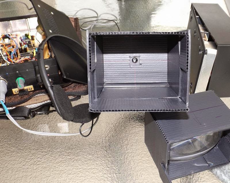
The RX detail 01 shows the business end of the photodiode, and the separate lens box (slides in and out for focus adjustment). Detail 02 shows the preamp with interchangeable photodiode modules - SFH213 for visible to 850nm, and the SFH213-FA for 850nm and below.
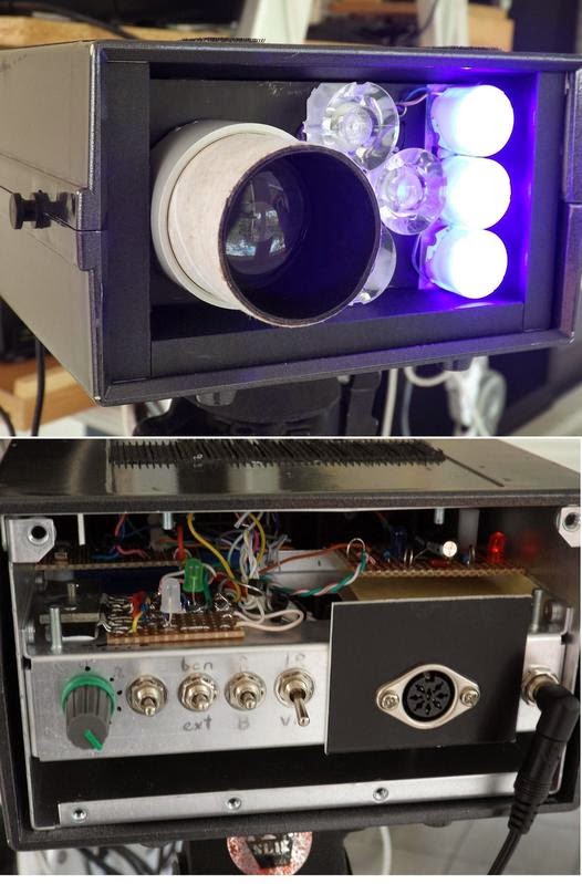
Multi-wavelength TX 01 (front and back image) includes several groups of fat LEDs (red, blue and 850nm) with matching lenses providing approx. +-5 degrees apertures. Also the PWM driver on 2x CAT4101 in parallel, external high current power connection, intensity control, and a PICAXE-controlled strobe or audio callsign/frequency sweep beacon.The whole assembly connects to the TRX control box (above) and can provide power to it, draw power from it, or have both DC sources in parallel.Enclosure includes a photo tripod mount on the bottom plate, and velcro strips on top to hold the RX front end.
Pocket-sized 10W IR TX is a small holiday project and still work in progress. The 7x LEDs are 2W each SFH4783 with an intrinsically narrow beam of +-10 degrees - quite appreciable for a naked LED of this size and possibly obviating the need for external optics in some applications. My usual CAT4101 drivers are included and capable of providing 2A at 50% duty cycle. Another Picaxe beacon is on the other side of the heatsink, and the voice modulator is still in progress.
The low-power multi-wavelength TX is another one day project, built to compare relative performances of 850 and 950nm IR. Three almost identical beams of red, 850 and 950 are transmitted in sequence with approx 100mA PWM running each diode. Unique CW ID has been coded for each wavelength.
6x SFH213 photodiode with individual preamps - quite a respectable low noise, high sensitivity front-end that works very well without external optics (SFH213 have a +-10 deg intrinsic apertures). A matching array of small fresnel lenses has been built and tested for narrow-beam reception, but a permanent box is yet to be added.. Some of the other gadgets seen in the foreground."
As mentioned earlier, Jan's experiments with NLOS signals utilizing IR is of particular interest to myself as I would like to continue experiments with VE7CA, on the other side of Georgia Strait...hopefully with Markus not having to move to a LOS position, but simply aiming across the Strait in a direct path, from his yard. Using Argo and QRSS3 mode, it will be interesting to see if any signals can be recovered from the cloud bottoms on some overnight runs.
More information on NLOS work may be found on the Australian Optical DX Group in Yahoo Groups as well as in the UK Nanowave Group....why is it that these two countries have so much homebrew fun??,,,and don't forget Clint's (KA7OEI) superb Optical Communications / Moduulated Light pages!
VK4EBP’s NLOS Lightwave Experiments – Part 2
 |
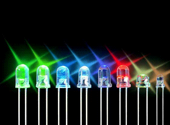
| Courtesy: http://www.ledsmagazine.com |
"Visible LEDs and optics: Some of my favourites include the LZ1 and LZ4 series from LedEngin used with matching spot lenses, or thick condenser lenses from old visual projectors. Also various Golden Dragon varieties with matching small plastic spot lenses. Average beam divergence with either configuration is about +-4 degrees. (Happy to provide detailed parts numbers.)
Infrared LEDs: Here we have a some good products from Vishay (TSHG series), with narrow beam (some go down to +-2 degrees) in the standard 5mm packages and max current of 100mA.

They can make nice pencil-beam arrays in combined series/parallel with 200 or more LEDS and no optics required, at less than 40c per LED. Lots of soldering though :). For the 950nm range (not extensively tested yet) the Vishay TSAL range of LEDs will do nicely.
LED drivers: I found a very neat IC to PWM-drive the LEDs at up to 1A - the CAT4101 from ON Semiconductors.
Usually have two in parallel for a peak of 2A at 50% duty cycle, giving me 1A average to drive the LED string.
At the reciving end I am now using a preamp loosely based on Clint's no-feedback design with some hum filtering and other post minor post-processing feeding to an audio amp, or to SpectrumLab."
"...tonight I am trying to compare 830nm against 940nm on a 600m short NLOS path. For this, I have just built a small TX with two "naked" LEDs - TSAL6100 (940nm) and TSHG8200 (830nm). Both have identical shapes of their radiation patterns with +-10 degrees. Each mounted inside of a square cross-section black cardboard tube side by side to ultimately give them a very uniform square beam of approx +-4 degrees. Each driven with 440Hz square wave at 100mA with unique morse identifier for each.
There is a third visible LED as well with its own cardboard collimator and morse ID, to serve as aiming tool and a kind of reference.
The purpose is to see whether 940nm would offer additional advantages in NLOS situations, due perhaps to better/different reflection, scatter, refraction or whatever physical processes might be involved.
An additional advantage might be removing my setup further away from visible light pollution. With the growing popularity of LED lighting in both household and the industry we are having a chance of less and less infrared pollution from traditional incandescent or similar sources - and making light comms more practical in urban environments - all with a simple IR filter at the receiving end.
Tonight's tests were not as productive as anticipated, but somewhat educational nevertheless. First of all the receiving location I picked on the map suffered from severe QRM from sodium street lights. I picked strongly all my "big" IR transmitters, but the visible and the "naked" ones were lost in the QRM, if present at all. I returned home, pointed the 150mW TX into nearby bushland and went for a walk. The red light reception vanished immediately after loosing sight of TX, followed quickly by the 940nm with the 830nm persisting the longest up to perhaps 100m - with the beam fired parallel to ground from upper storey into the crowns of the trees. Reception required pointing the receiver slightly up, intersecting the TX beam somewhere in the tree branches.
Briefly - I confirmed what I already knew: - IR is far superior to visible for NLOS work - indeed visible light is of no use.
- Low elevations and scatter from ground objects is superior to high beam elevations.
A new observation (that I would like to confirm) is that 900+nm is not worth bothering about. It is known that 950nm suffers from greater scatter in atmospheric particles than 850, but this proved to be more of a hindrance than help in NLOS work.
Another practical observation is that the 950nm version of the common SFH213 photodiode (SFH213-FA) works very well in receiving 850nm whilst filtering out lots of the visible pollution (well, perhaps except the sodium lamps!).
I started tonight's session before sunset and got very good NLOS reception of my large IR TXs - in what could be described as quite a bright twilight. (I carry two plug-in front-end modules each with one of the two photodiodes and the input FET.)
Another holiday project - a pocket-sized 10W TX! I found new IR LEDs - SFH4783 - rated at 2W, barely 1.65V of Vf, and intrinsically narrow angle of +-10 degrees. This means no optics, and up to seven of them in series on a small heatsink can be run from a 12V SLA battery.
 |
| Osram SFH4783 |
This reminds me of yet another observation - out of my several large 850nm TXs the best performers are the naked narrow-angle multiple LED arrays - and the one containing 3 high power broad-beam LEDs with spot optics performing the worst. Well the lenses are designed for visible LEDs and I have no guarantee that the material refraction angles and loses are acceptable in the IR range...
Returning to Steve's questions and our general discourse:
..is it (the RX) fairly small and portable...and lensless? (cont'd)...
VK4EBP’s NLOS Lightwave Experiments – Part 1
Jan's posting was chalk-full of useful "hands-on" information and was just what I needed to hear and led to some extensive and interesting conversation, well worth passing on to others. I could summarize Jan's work in point form but I think it is more interesting to let Jan describe it himself.
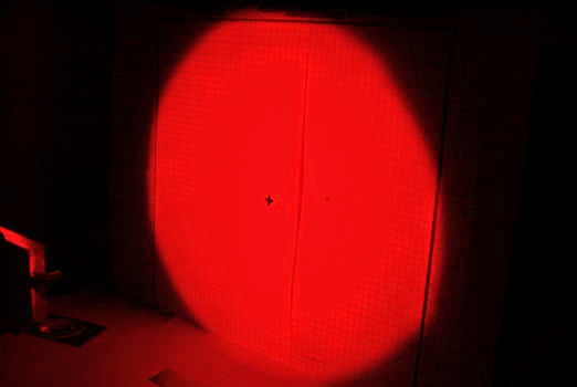
"Finally some success with over-the-horizon light. Briefly - several transmitters of several watts each were fired
simultaneously with the beams aimed at the tops of nearby trees, each
transmitter sending unique combination of tones (direct AM).
 |
| Osram SFH213-FA |
plastic lens approx. 7x12cm. Receiver was aimed towards the TX site and
pointed just over the horizon.
Aural reception of 850nm infrared signals was very good. There was no
trace of TX signals in visible or near-visible spectrum. Signal quality on
850nm was further improved with an infrared-filtered photodiode (SFH213FA, 950nm peak) which provided some attenuation of suburban lights QRM.
My earlier series of experiments over the years was aimed at achieving NLOS short-range communications in a light-polluted metropolitan
environment. I had limited successes with high-elevation cloudbounce over
several km distance using both red and infrared. Very poor results with
high-elevation scatter in clear air, with blue light appearing the best,
and green and yellow the worst for the purpose. More recent tests
suggested that low elevations with infrared light offer a reliable link,
and today's results seem to confirm that.
More to follow! 10km test tomorrow night. 73 de Jan vk4ebp"
Jan has been testing several different TX emitters / wavelengths, simultaneously, each with a different CW identifier. His path started with a 1km hop through his local residential neighbourhood, with significant obstructions shown below. Later the path was stretched to 10km. His observations involving IR were particularly helpful:
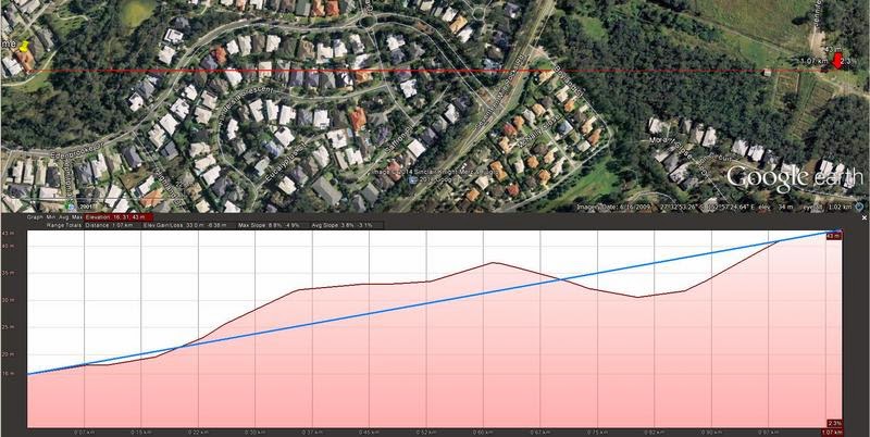 |
| 1km NLOS Path |
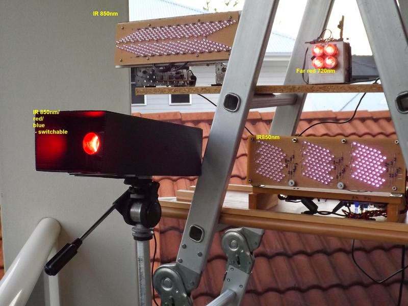
deep red 10W with condenser lens, 3x1W Golden Dragon 850nm IR LED with
+-4deg spot lenses, and 3x 4W LZ1 blue with +-5 deg spot lenses. Manually
switchable by my very patient family members on request via walkie talkie
from the receiving site. The two multi-LED arrays are approx 10W each in
total, one containing a multitude of +-3 deg SFH4550, and the other
+-10deg some other LEDs - do not remember after many years since building it. The small heatsink block contains 4x LZ1 far red, run at about 8W
total."
"At the NLOS location 1km away I was able to copy all the 850nm TXs and
none of the visible/borderline ones.Last night I tried 10km distance.
The topography is theoretically line-of-sight, but isolated from the receiving site by a thick bushland in nearby park. I was firing the transmitters about 3 degrees above what
would be line of sight, thus having about half the beam into the air and
another half scattered in the tree tops near the TX site.
I was able to weakly copy only one of the transmitters - the array of 200 or so of the +-3deg IR LEDs. At the moment I am not certain whether it was from atmospheric or tree scatter.
From earlier tests I observed that IR penetrates very well into the bushland, long after the visible beams were lost both visually and electronically. Similarly, it seems to propagate well into suburban
streets. Presumably the longer wavelength is "seeing" rough surfaces like tree trunks and brick walls as actually shiny and reflecting...."
".... a bit more about my transmitters. (cont'd....)
On Making Nanowaves – Part 6
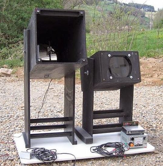
After several weeks of reading, planning and homebrewing, both the transmitter and the receiver boxes were finally finished....at both ends of the path!
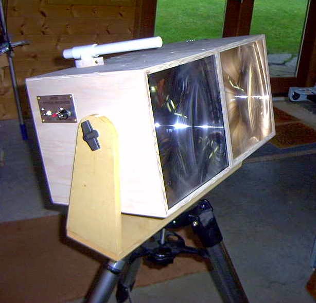
After the transmitter and the receiver had been accurately focused (the receiver's photodiode at the fresnel's focal point and the transmitter's secondary lens properly positioned) both enclosures were screwed together and mounted on a tripod.
Markus, VE7CA, had checked-out a suitable location not far from his home QTH on the road to one of the local ski-hills. This gave him an unobstructed view to my location on Mayne Island, about 54km to the southwest. I had planned to set up in my front yard, about 15' above sea level and on the eastern shoreline with a direct shot to Markus.
Even though we were using LEDs rather than lasers, I still felt somewhat uneasy as our path crossed directly over the runways at Vancouver International (around the path midpoint) as well as the main ferry lane between Vancouver Island and the B.C. mainland. Considering the distances involved, I probably need not have worried as the light, although bright, would cause no physical harm other than possible momentary distraction or curiosity. If one of the ferries had been approaching the path, I had planned to shut down until it had passed as it would have been hard to convince authorities that the light really was not a laser, before they carted me away!
After waiting for the usual winter B.C. rain to subside, we finally had a promising evening shaping up, although somewhat cold. Markus, accompanied by Jim, VE7BKX, loaded his vehicle and headed for the mountains. With neither of us having 2m portable radios, we somewhat guiltily reverted to cellphones to announce setting-up status.
 |
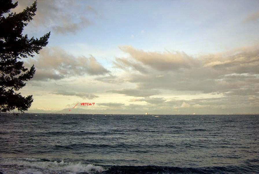
| VE7CA/7 |
Almost immediately I heard his beacon signal although there was no visible sign of his light.
Before final alignment I made a quick recording of his signal.
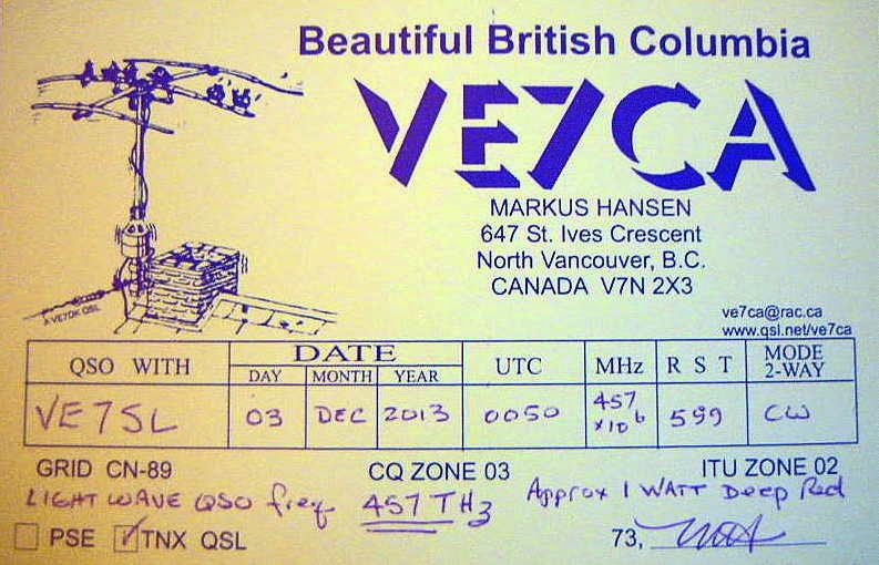
Neither if us had any real idea of what type of signal strength to expect and we were both very surprised to hear how strong the signals were. Once we had both aligned and our lights were now visible, we switched to CW mode and proceeded to work each other in typical QSO mode.
Hear is a recording of Markus sending my RST report.
Signal reports as well as grid squares were exchanged just to make everything 'official'. We then settled into a nice twenty-minute ragchew until the cold winter air took its toll on our fingers forcing us both to close down and pack up for the night.
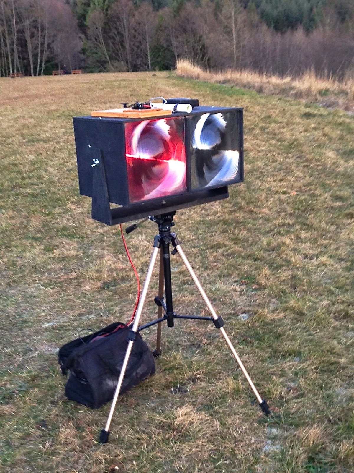
Markus grabbed a short cellphone video from his end which shows the still fairly bright twilight skies and the LED signal source:
Earlier, John (VE7BDQ) had made the decision to not build a transmitter as he preferred not to go portable. Both of us were interested in pursuing a possible non-line-of-sight (NLOS) path by using either 'cloudbounce' or 'clear-air scattering' which would allow John to set up in his backyard. The path between us is much shorter than the VE7CA/7 path as can be seen in the map below:
 |
| Courtesy: https://maps.google.ca/ |
For one-way beaconing, I plan to add a more accurate crystal-controlled tone module so that my CW signal's frequency is precisely known and can be watched for in the very narrow bandwidth window of Argo or Spectran over a given period of time. Even at these slower speeds, QSOs exchanging the minimum required information can still be made relatively quickly. Hopefully any reception at all of my signal at John's location will excite him into building a transmitter as well. Completing a two-way contact using the NLOS mode would be a very interesting challenge.
In the meantime, Markus and I have been seeking out possible new locations for his remote work, using "HeyWhat'sThat Path Profiler" web site. This site quickly indicates the distance and headings between any two points and draws a geographic contour of the path showing any obstructions.
 |
| Courtesy: http://www.heywhatsthat.com/profiler.html |
Markus hopes to get out to one such favourable location in the Fraser Valley mountains, before the weather turns nasty once again.
If there is anyone in the Vancouver lower mainland region that might be interested in building a lightwave station to join us in the fun, please do not hesitate to make contact with any of us...we would love to hear from you!
If you are a member of the Radio Amateur's of Canada (RAC) and receive their 'TCA' journal, please watch for our upcoming article in September's issue..."A West Coast Lightwave Project".
On Making Nanowaves – Part 5
With the fresnels in hand, a pair of plywood box enclosures were built...one for the receiver and one for the transmitter. Eventually they would be coupled together so that both would be pointing at the same distant spot.

The next step was to use John's design to mount the receiver and transmitter modules so they could be locked into position once aligned properly. His system used the 1/4" split shaft locking mechanism removed from an old Allen-Bradley potentiometer to hold a short length of rod fastened to the module's case.

This allowed the shaft to be moved forward and backward for focus while the slot in the mounting plate allowed for vertical centering. The plate mounting mechanism itself allowed for lateral centering. This system allowed for the locking of the receiver's photodiode at the exact focal point of the fresnel lens.The same scheme was employed for the transmitter's LED as well, since accurate focusing was critical there also.
In order to focus as much of the LED's light onto the primary fresnel lens, a small inexpensive (secondary) collimating lens was required. This assured that the fresnel was properly illuminated out to its edges and no further. Any light spilling over the edges of the fresnel would just be wasted.
Our particular fresnel had an effective aperture of 260mm and a focal length of 200mm, producing an F-number (f/D ratio) of .76.... Clint suggested that our collimating lens should have an F-number of ~ 1 - 1.2 and be a PMN (Positive MeNiscus) type and that we hedge our bets by trying lenses above and below that value. Ideally the collimator should be at least 25mm in diameter for ease of mounting and, when perfectly illuminating the fresnel, be as close to the LED as possible, if not touching it. Just placing a less than ideal secondary too close to the LED would end up over-illuminating the fresnel, while having it too far away would under-illuminate it.
Accordingly, four small glass collimating lens of various F-numbers were purchased from Surplus Shed at around $4 each. Each lens was then mounted on a drilled-out piece of PCB material using 'JB Weld'.

Once cleaned-up, the lens board was then positioned directly over the center of the LED on a machine-screw carriage mount. The carriage allowed the lens to be locked into position once it was correctly positioned. All four lenses were tested to see which one would correctly illuminate the fresnel while still being as close to the LED as possible.

The eventual winning secondary lens was #L10016 (.9 f/D) which allowed for a sharp and fully-illuminated fresnel while being just a few millimeters above the LED.
The next step was to adjust the entire LED and secondary carriage for the sharpest focus on a distant flat surface. This was done over a distance of about 200' and was a fairly fine adjustment.
Once done, it was actually possible to see the two fine wires connecting to the LED die on the distant projected image.

With the final focusing taken care of, the tone modulator and MOSFET LED driver were installed. This used an IRF540 switching FET, driven by the digital tone signal to control the current through the LED.

All we could do now was patiently wait for a nice clear evening to put the system to work.
The next step was to use John's design to mount the receiver and transmitter modules so they could be locked into position once aligned properly. His system used the 1/4" split shaft locking mechanism removed from an old Allen-Bradley potentiometer to hold a short length of rod fastened to the module's case.
This allowed the shaft to be moved forward and backward for focus while the slot in the mounting plate allowed for vertical centering. The plate mounting mechanism itself allowed for lateral centering. This system allowed for the locking of the receiver's photodiode at the exact focal point of the fresnel lens.The same scheme was employed for the transmitter's LED as well, since accurate focusing was critical there also.
In order to focus as much of the LED's light onto the primary fresnel lens, a small inexpensive (secondary) collimating lens was required. This assured that the fresnel was properly illuminated out to its edges and no further. Any light spilling over the edges of the fresnel would just be wasted.
Our particular fresnel had an effective aperture of 260mm and a focal length of 200mm, producing an F-number (f/D ratio) of .76.... Clint suggested that our collimating lens should have an F-number of ~ 1 - 1.2 and be a PMN (Positive MeNiscus) type and that we hedge our bets by trying lenses above and below that value. Ideally the collimator should be at least 25mm in diameter for ease of mounting and, when perfectly illuminating the fresnel, be as close to the LED as possible, if not touching it. Just placing a less than ideal secondary too close to the LED would end up over-illuminating the fresnel, while having it too far away would under-illuminate it.
Accordingly, four small glass collimating lens of various F-numbers were purchased from Surplus Shed at around $4 each. Each lens was then mounted on a drilled-out piece of PCB material using 'JB Weld'.
Once cleaned-up, the lens board was then positioned directly over the center of the LED on a machine-screw carriage mount. The carriage allowed the lens to be locked into position once it was correctly positioned. All four lenses were tested to see which one would correctly illuminate the fresnel while still being as close to the LED as possible.
The eventual winning secondary lens was #L10016 (.9 f/D) which allowed for a sharp and fully-illuminated fresnel while being just a few millimeters above the LED.
The next step was to adjust the entire LED and secondary carriage for the sharpest focus on a distant flat surface. This was done over a distance of about 200' and was a fairly fine adjustment.
Once done, it was actually possible to see the two fine wires connecting to the LED die on the distant projected image.
With the final focusing taken care of, the tone modulator and MOSFET LED driver were installed. This used an IRF540 switching FET, driven by the digital tone signal to control the current through the LED.
All we could do now was patiently wait for a nice clear evening to put the system to work.
On Making Nanowaves – Part 4
Researching suitable LEDs for our lightwave project forced me, once again, to the bottom of the learning curve. Like the variety of photodiodes being used in simple lightwave systems, there were a myriad of LEDs experimentally lighting up the skies both in the UK and in the U.S.
It seemed that the present flavor-of-the-day in terms of LEDs was the Luxeon III, a 3W / 1.4A device being produced by Phillips.....or rather.....was being produced. Apparently our new found interest in lightwave communications had been coincidental with the retirement of this popular LED and all stock had been depleted! Although still available in some wavelengths, there were none in the desired 'deep red' portion of the spectrum that we had chosen for our system.
All was not lost however as a 'replacement', largely untested by the lightwave community, spec'd-out at a lower power but with a somewhat more efficient design. The new device was the Luxeon 'Red Rebel' and rated at 700ma. ....apparently no slouch at all.
I had also been watching the various offerings available on e-bay which provided a number of tantalizingly inexpensive options. Many of the LEDs from China appeared to offer good promise and may well be good performers, but most appeared to be lower-quality knock-offs of the name-brand models.
These higher-powered LEDs, on close examination, usually contained two or more separate LED die behind the lens. A single light source is required to achieve maximum focusing / lens illumination efficiency and although tempting, should probably be avoided. 'Safe' names to look for include Philips, Osram and Luminus and often, bargains can be found on e-bay when NOS is being disposed of.
 Like most 'power' LEDs, the Rebel needs to be mounted on a heatsink otherwise catastrophic destruction would be immediate. The usual method of heatsinking is to attach the LED (by solder or adhesive) to a copper star-shaped interface which is then fastened to a small heatsink.
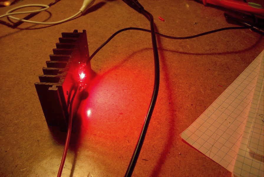
The interfaces can be purchased separately but soldering the LED can be challenging without overheating it. They can also be fastened with JB Weld and enough pressure to ensure a firm bond without damaging the LED. An easier alternative is to procure the LED already mounted on the interface as shown here.
Once adequately heat-sunk, voltage can be applied to the LED after taking measures to limit the current to safe levels. Although these LEDs are very small, they emit an exceptionally bright light and must be treated with care. The Rebel is shown here, shortly after first applying voltage. The current in this test was just 100ma. Although they are rated at 700ma, I have run this one up to 1A without failure but it is normally run at the rated current.
The next task was to tackle the 'antenna' which, in a lightwave system, is the lens. Many of the UK amateurs were having good results with inexpensive 4"-5" magnifiers mounted inside ABS or PVC tubing. The remainder, and those in the U.S., were using plastic Fresnel lenses mounted in homebuilt plywood boxes of various designs. Clint's (KA7OEI) website contains a vast amount of valuable hands-on info describing the latter and we chose to go via that route.
Like the large variety of both photodiode and LED selections, fresnels were no different. Once again there was a lot of information to digest while learning about the various types. Eventually, John, Markus and myself each purchased two plastic fresnel lenses from 3DLens in Taiwan. One would be used in the receiver box while the other was for the transmitter. These were 26cm square lenses, model A260.
Unfortunately I no longer see these particular lenses being offered....hopefully it is only a momentary depletion of stock. There are many different sizes and types of fresnels out there....some if them perfect for this type of use and others not so good, so think carefully before buying anything and know what you are getting. Studying Clint's pages regarding fresnels will help immensely.
Things to pay attention to are the focal length and groove 'pitch'. For a typical 10"-12" lens, look for something around 10-12" focal length, otherwise the mounting enclosure will get too deep and awkward to handle. Front surface 'groove pitch' should not be too fine...something around .5mm is good but our finer (.2mm) seemed to work well also.
Now that the LED had been mounted and the fresnel lenses were in hand, the next task would involve the focusing mechanism and alignment. Thankfully John had devised a smart method for mounting and adjusting focus a few weeks earlier, when we were still working on receivers.....
It seemed that the present flavor-of-the-day in terms of LEDs was the Luxeon III, a 3W / 1.4A device being produced by Phillips.....or rather.....was being produced. Apparently our new found interest in lightwave communications had been coincidental with the retirement of this popular LED and all stock had been depleted! Although still available in some wavelengths, there were none in the desired 'deep red' portion of the spectrum that we had chosen for our system.
 |
| Courtesy: http://www.luxeonstar.com/luxeon-rebel-leds |
All was not lost however as a 'replacement', largely untested by the lightwave community, spec'd-out at a lower power but with a somewhat more efficient design. The new device was the Luxeon 'Red Rebel' and rated at 700ma. ....apparently no slouch at all.
I had also been watching the various offerings available on e-bay which provided a number of tantalizingly inexpensive options. Many of the LEDs from China appeared to offer good promise and may well be good performers, but most appeared to be lower-quality knock-offs of the name-brand models.
These higher-powered LEDs, on close examination, usually contained two or more separate LED die behind the lens. A single light source is required to achieve maximum focusing / lens illumination efficiency and although tempting, should probably be avoided. 'Safe' names to look for include Philips, Osram and Luminus and often, bargains can be found on e-bay when NOS is being disposed of.
 |
| Courtesy: http://www.luxeonstar.com |
Once adequately heat-sunk, voltage can be applied to the LED after taking measures to limit the current to safe levels. Although these LEDs are very small, they emit an exceptionally bright light and must be treated with care. The Rebel is shown here, shortly after first applying voltage. The current in this test was just 100ma. Although they are rated at 700ma, I have run this one up to 1A without failure but it is normally run at the rated current.
 |
| Luxeon Red Rebel at 100ma. |
Like the large variety of both photodiode and LED selections, fresnels were no different. Once again there was a lot of information to digest while learning about the various types. Eventually, John, Markus and myself each purchased two plastic fresnel lenses from 3DLens in Taiwan. One would be used in the receiver box while the other was for the transmitter. These were 26cm square lenses, model A260.
Unfortunately I no longer see these particular lenses being offered....hopefully it is only a momentary depletion of stock. There are many different sizes and types of fresnels out there....some if them perfect for this type of use and others not so good, so think carefully before buying anything and know what you are getting. Studying Clint's pages regarding fresnels will help immensely.
Things to pay attention to are the focal length and groove 'pitch'. For a typical 10"-12" lens, look for something around 10-12" focal length, otherwise the mounting enclosure will get too deep and awkward to handle. Front surface 'groove pitch' should not be too fine...something around .5mm is good but our finer (.2mm) seemed to work well also.
Now that the LED had been mounted and the fresnel lenses were in hand, the next task would involve the focusing mechanism and alignment. Thankfully John had devised a smart method for mounting and adjusting focus a few weeks earlier, when we were still working on receivers.....
On Making Nanowaves – Part 3
Having studied many of the receiving systems being used by others, it seemed that designs ran from the 'very simple' to the 'very sophisticated'. Once again I looked to Roger's experimental work involving receivers since the one he had been using had evolved over a period of several months and several tweaks. The design that he used was an adaptation of the original low-noise PIN diode laser receiver designed several years ago by K3PGP and shown here on K3PGP's Experimenter's Corner.
Roger's adaptation, shown below, appeared to be getting excellent results when used in his over-the-horizon clear air scattering tests.
Although Markus, John and myself all built the same design, it is interesting to see the end results, as each used a different construction method.
John chose to use perfboard and point to point-to-point wiring:
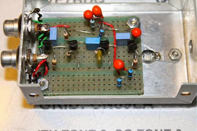 |
| VE7BDQ's Perfboard RX |
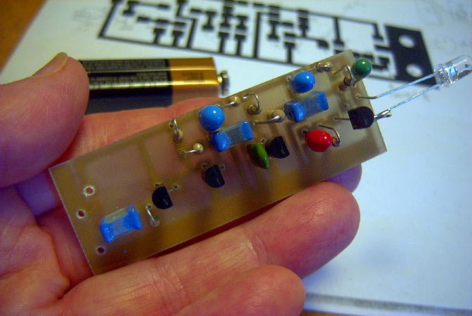 |
| VE7SL's PCB RX |
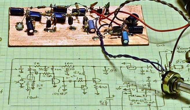 |
| VE7CA's Dead-Bug Style RX |
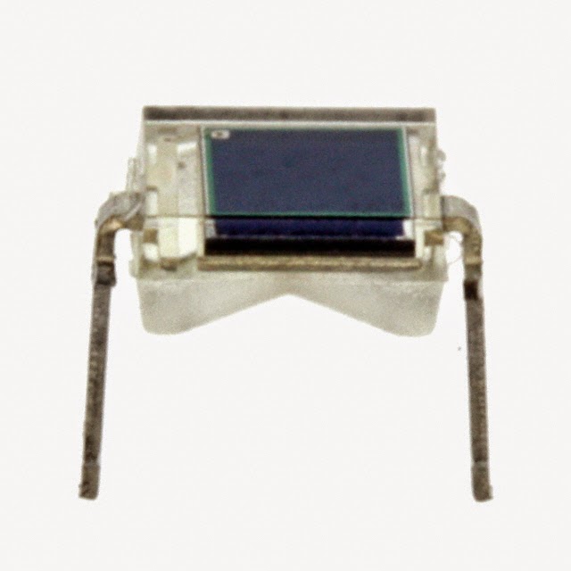 All of us used the Osram BPW34 PIN diode for the detector after having it recommended by Clint in e-mail 'detector discussions' as being a good performer . It is still readily available from the usual places, at around eighty-cents.
 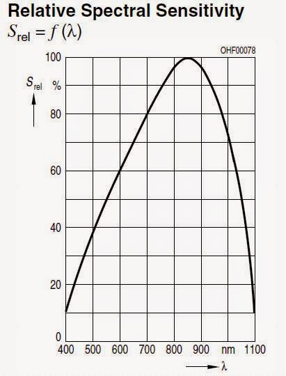 |
| BPW34 Spectral Range |
Many silicon PIN photodiode detectors are available with filters that let them achieve maximum sensitivity at the lower IR range while blocking the unwanted higher frequency visible light sources. Such is the case with this one, available as the BPW34FA. If you wanted to run an all IR system, reducing visible light QRM, this detector might be a better bet.
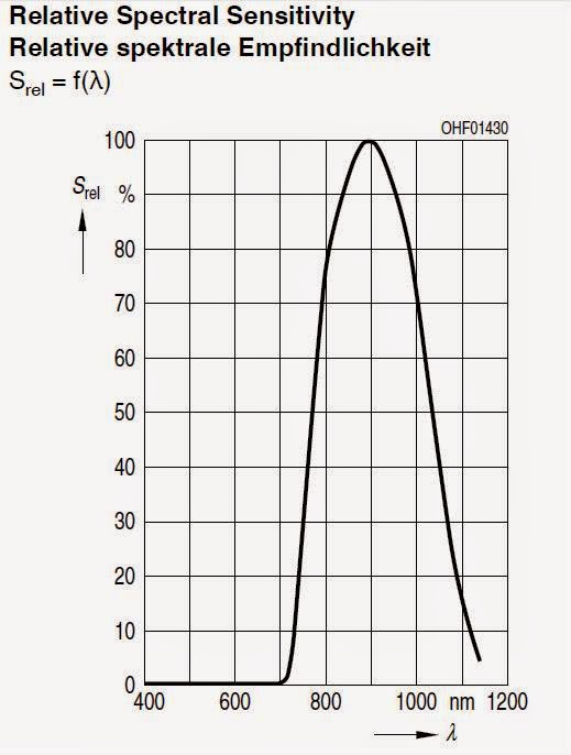 |
| BPW34FA Spectral Range |
When it comes to diode detectors, there are always new challengers appearing in the marketplace. There are still many opportunities for experimenting when it comes to optimizing the front-end of your receiver.
When coupled with its focusing lens in the final stage of construction, the receivers are amazingly sensitive. Even the slightest hint of a light source, often invisible by eye, would produce a response from the system....even starlight!
One of the first sounds detected was a low-pitched and repetitive 'thump-thump' which turned out to be the wingtip strobe lighting of jet aircraft activity approaching and departing Vancouver International Airport. After several nights of listening it was apparent that the strobe lighting could be detected from at least 70 miles out and from aircraft still above 10,000'. Panning over to the runway (about 25 miles away), I could often detect the strobes from departing aircraft even though they had not appeared above my sea-level horizon. Eventually I would see them rise above the horizon, about a minute after hearing them on the runway while on their takeoff roll. I suspect the propagation mode would be a form of clear-air scatter since there was no direct line-of-sight to the signal source when initially heard.
Panning the receiver slowly along the many miles of coastal mainland, on the other side of Georgia Strait, revealed many signals, most of them with different audio signatures. Some sounded rough and buzzy, like an unfiltered CW note, while others were T9 and very clean. Most had different repetition rates resembling radar sweep speeds but, once again, most sources were not visible to my eye...nor were they located when scanning the signal source with binoculars. I suspect that most signals were from various fixed lighting installations either strobe lighting or area flood lighting. Some targets appeared to be slowly moving and were found to be coming from tankers and container ships travelling along the far coast line. Hearing so many of these modulated lightwave signals was certainly an interesting experience and something I had not really expected. Even individual stars would produce a detectable 'hum' as the receiver/lens combination was aimed directly at them.
My one and only daylight test revealed extremely high levels of hum from the bright sky and, no doubt, front end overload desensitising....but the sudden sound of a buzzing bee in the headphones turned out to be just that, as the reflected light from its wings was being modulated by the rapid flap-rate....all very eye-opening to me and totally unexpected.
Here are some recent audio recordings made during a period of heavy cloud cover over Georgia Strait. All are on the far mainland coast or further inland and most sources were not visible to my eye.
- Landing aircraft strobes at Vancouver International ~ 30 miles.
- Aircraft over Georgia Strait, ~ 40 miles.
- Unidentified with odd repetition rate.
- Washington coast unidentified ~ 30+ miles.
- Washington coast unidentified 2.
- Washington coast unidentified 3.
I think such a system would make a wonderful 'science-fair' project for a budding student, complete with recordings....but perhaps it has all been done before!
For a very in-depth study of various current RX designs, see the Optical Receivers page of KA7OEI.
With all three receivers working well, the transmitters would be next....


