Posts Tagged ‘Microcontrollers’
 FreeTrak progress
I have made some progress with the FreeTrak PIC based APRS tracker. I found a slightly newer version of the PICFlash programming software. At first this gave exactly the same warning message as the original version. But after a bit of random clicking I tried again and this time the software reported that it was writing to the chip. It verified OK as well. I don’t know exactly what I did, but at least that hurdle was now passed.
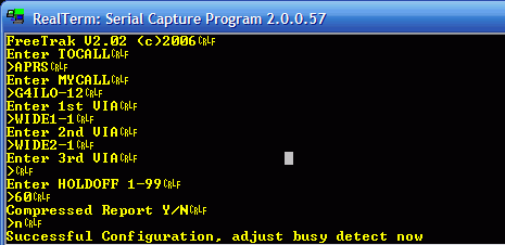 |
| FreeTrak configuration |
I set the DIP switches on the EasyPIC board to link the PIC pins used for serial I/O to the serial output. That didn’t seem to work the first time, either, but at the second attempt at powering up I saw the configuration prompt appear in the terminal window. I was able to complete the FreeTrak configuration with the PIC in the development board.
Next, I changed a DIP switch to put the chip in Run mode. Using a utility called NMEAGen I began sending simulated GPS messages to it using the same serial connection I used for configuration. The LED began flashing at 1 second intervals and using a crystal earpiece on the output pin I could hear the familiar sound of 1200baud packet bursts. I don’t know why it appears to be transmitting at 1 second intervals, but perhaps it is something to do with the simulated GPS data.
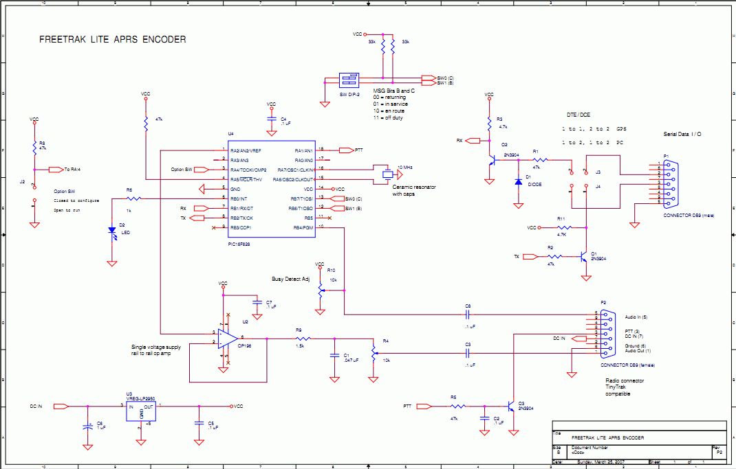 |
| FreeTrak schematic |
So FreeTrak appears to be working. All I need to do now is build it on to a circuit board and attach it to my GPS module and a radio. Here’s where I could use a little help from readers. The AFSK audio output of the FreeTrak uses an obsolete op-amp which is unobtainable. I presume I could just replace this with a simple transistor amplifier stage using a 2N3904 or similar, but do I really need anything at all, given that the audio will drive a sensitive microphone input? Could I get away with just a DC blocking capacitor and a trimpot to set the level?
The other thing I’m unsure about is how to interface the FreeTrak to my GPS module. I think the circuit shown is intended to work with GPS devices that use 5V TTL or even RS-232 signal levels. The data sheet for my bare GPS module states quite clearly that the absolute maximum voltage on any of the pins is 3.3V. The serial lines on the PIC measure close to 5V. How to connect them?
Mistaken identity
A couple of weeks ago I came across FreeTrak, a PIC based APRS tracker developed by N0QBH. I have wanted to build a small ‘grab-and-go’ tracker for a while now. The FoxTrak works fine but is too big and bulky by the time it is paired with an HT. The TH-D72 is too much hassle as I need strong reading glasses to see the LCD screen and inevitably go out with some essential menu option disabled. Consequently these days I rarely bother taking APRS with me when Olga and I go for a walk around town.
I sent off for a couple of PIC 16F628A microcontrollers, thinking that I could program them in my EasyPIC5 development board. But when I tried, I immediately hit a snag.
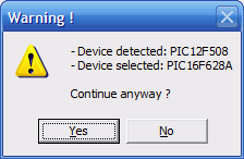
My PICFlash programmer detects a PIC 12F508 instead of a PIC 16F628A.
I don’t think I’ve been sold a fake MCU. If I remove the 16F628A so there is no micro plugged in at all I still receive the same warning. So I don’t know what to do. I’ve bricked too many PIC chips by programming them with the wrong settings to try crossing my fingers and clicking Yes. So it looks like my FreeTrak project is not going to get off the ground.
A cheap LCD
A packet arrived from China this morning containing a 16×2 LCD module which I purchased for the absurd sum of £1.93 including shipping. That wouldn’t cover the postage from a UK supplier. I don’t know how the Chinese do it and make a profit.

I bought the module with the intention of using it to make a user interface for my Parallax Propeller beacon. Having ordered it I was not sure how to interface the LCD to the Propeller so I chickened out and ordered an LCD UI module from Gadget Gangster. This is rather more expensive (though still a reasonable $29.99) but it includes a 4-way + depress button for menu navigation, plus a separate red button. It plugs straight into the Gadget Gangster board. I reasoned that even with the hardware sorted the software would be enough of a challenge.
I have rather ambitious plans for this beacon. Perhaps over-ambitious. After reading Alex G7KSE’s blog post about his Arduino based MSF 60kHz receiver I’m interested in interfacing one of the inexpensive MSF receiver modules to the Propeller. I could use this to display an accurate clock and also to control the start of WSPR beacons. As I’m a bit of an accurate time nut and have two radio controlled clocks in the shack (and a radio controlled watch) it is really no trouble to press a button to start the beacon at the beginning of an even minute and then keep time from there. But that isn’t the point really, is it? What could be cooler than a shack clock that is also a WSPR beacon?
This microcontroller stuff is new to me and I have a lot to learn about it. One question I have is what do constructors who use Arduino boards or similar things like the Gadget Gangster do when they want to make a finished project? Do you just buy another development board to use for the next project, or are there simpler boards with just the microcontroller and its essential ancillary components which you use for the final version? I guess I’d still want the ability to update the software (firmware?) so there isn’t much of the Propeller Platform board that I wouldn’t be using.
Propeller does WSPR
Through Eldon, WA0UWH I have discovered another blog to add to the blogroll: that of Jeff, KO7M. Jeff is interested in a lot of the same things I have been (including light aviation: an ambition of mine when I was in my 20s but which I could never afford to take up.) But what really piqued my interest was that he has just got a Parallax Propeller to generate a WSPR signal.
This is one of the things I was interested in trying. But I never got further than wondering how to implement the fractional frequency shifts of the WSPR signal, which uses 4 tones shifted by just under 1.5Hz from each other. Jeff has apparently found that a 2Hz shift is good enough to be decoded, allowing WSPR to be sent using the integer frequencies the Propeller chip can easily generate.
Once I have finished the Tiny Keyer project and can get back to the Propeller I will be trying this myself. My ambition at the moment is to make a multi-band multi-mode (OPERA, WSPR and perhaps QRSS as well) standalone beacon with an LCD panel to enable me to choose the band and mode. We’ll see how far I get, but having two other people working on the same ideas should certainly make the task easier!
Trials and tribulations
I’m sorry if you are one of the many people who have sent me email expecting a reply, but unfortunately answering emails is one of the things I very often never get around to. Although it might seem from the blog that I am getting back to normal, everything I do still takes me a lot longer than it did when I was fit and well and I’m more prone to making stupid errors. I’m happy that I’m still able to do some of my ham radio activities but what I achieve is often accomplished only after a lot of frustration.
Today the Simple Keyer Chip from Steve Weber arrived in the post. I verified the behaviour of the chip I’d programmed, then replaced it with the new one. I was pleased to find that it now operated at the correct speed – the sidetone was now audible to humans rather than bats and the default speed was rather more sensible. Obviously I’d messed up some setting of the programmer – but the keyer still ignored the dot paddle. I began to suspect that this meant there was something wrong with my wiring, but between my limited field of focus and my shaky hands it took the entire morning – culminating in a lot of bad language – before it eventually dawned on me what was the trouble.
To cut a long story short, the cause of the problem was the 3.5mm socket I was using for a key jack. It had three terminals which I thought were for tip, ring and sleeve, dash, dot and ground. But it was a mono socket! There was no ring connection. One of the three terminals was linked to the other and disconnected when the plug was pushed in, intended to silence a speaker when phones were plugged in. It took me an entire morning including checking the wiring of two morse keys before I discovered my stupidity.
I hunted in my parts drawers and eventually discovered a proper 3.5mm stereo socket. After connecting that in place of the other one I confirmed that the keyer worked as expected. But the frustrating search for the solution had made me tired so I decided to leave the task of drilling the box and finishing the keyer for another day, thereby adding to the list of unfinished tasks alongside the unanswered emails.
Another thing that annoys me is my Rapid Electronics HY3003D bench power supply. It has a rather inconvenient fault for a power supply that is used in a radio shack. The voltage regulation circuit suffers from RFI. If any of my radios transmits, the voltage increases. In some cases it could increase to a level that could damage the circuit I am testing, though fortunately that hasn’t happened yet.
I don’t always remember to put my APRS gateway or the WSPR (or Opera, which I have been testing today) beacon into receive-only mode whenever I’m working on something. (I’ve tried clamp-on RFI suppression ferrites on the mains lead and they made no difference.)
First spin of the propeller
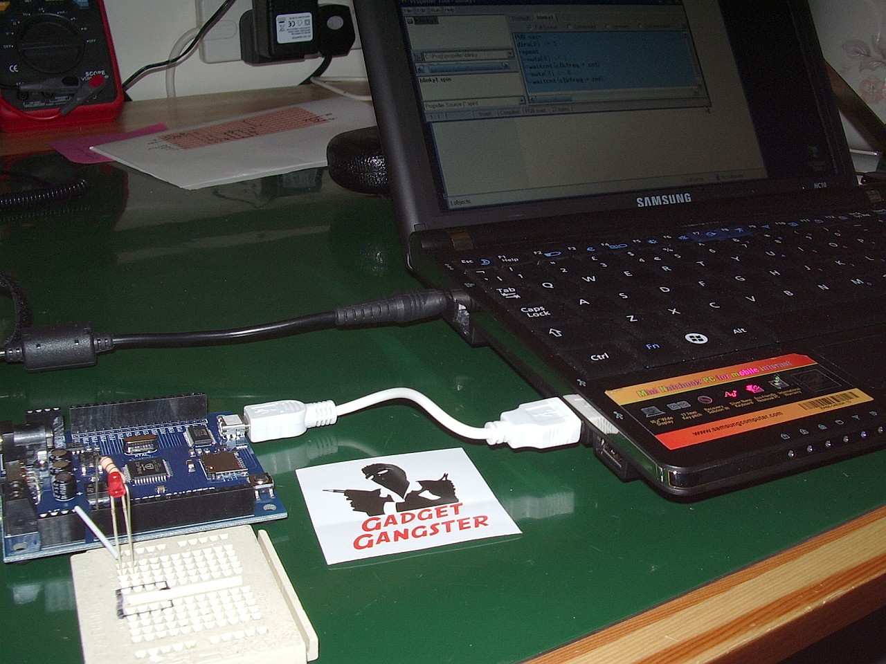
A new toy dropped through the letterbox today. It is a Gadget Gangster Propeller Platform USB demo board for experimenting with the Parallax Propeller microcontroller. If you haven’t heard of the Parallax Propeller before then it is an inexpensive micro chip that contains eight processors called cogs (as in gear wheels) that can run independently in parallel. It’s quite a bit different from the Microchip PIC or Atmel devices which have a single processor architecture similar to an ordinary computer.
I sent off for the board just after Christmas, after reading about it in Eldon Brown WA0UWH’s blog. Eldon posted code showing how the board could be used as a QRSS beacon. I was quite excited by the idea of a device that with simple programs even I could understand could be made to emit RF.
I sent off for the board on 27th December choosing the low cost untracked USPS air mail shipping option and it arrived today, 4 January – much quicker than expected. What’s more, there were no nasty customs charges! Gadget Gangster still has a special offer of $10 off for the board, so if you fancy getting one of these to play with now is the time to do something about it.
I was very impressed at the speed with which Gadget Gangster processed my order. What you get, though, is just the board. You will need to provide a power supply (7.5 – 12V with a 2.1mm barrel connector, centre positive) and a USB cable with a mini-USB jack at one end. These seem to breed in my junk box so that was not a problem. You will also find useful a small breadboard and some hookup wire to attach components to the board and test your programs.
I installed the Propeller Tool – a free download from the Parallax website, connected the board to my Samsung NC10 netbook. I then tried the Blinky Light tutorial from the Gadget Gangster site. It didn’t work – until I connected the LED the correct way round (stupid newbie error!)
Over the next few days I’ll be working through the tutorials to get the hang of the system. Then I’ll take a look at Eldon’s QRSS beacon code and adapt it to send my own call. I’d like to make a WSPR beacon. I don’t know yet if that will be possible, but I’m looking forward to playing with this Propeller chip and using it in some radio-related project. Watch this space!
Simple keyer trouble
It should have been simple. I needed a basic CW keyer that would allow me to use a paddle with my homebrew QRP / QRPP rigs because my shaky hands make sending Morse with a straight key too difficult at the moment. I also needed to be able to record a message and play it once or repeatedly until I heard someone reply or was spotted on the reverse beacon network.
A couple of years ago I built a DC20B QRP transceiver. I didn’t like it very much and eventually sold it on eBay but I did like the keyer built into it which used an ATTiny13 microcontroller. One day, I thought, I would build a keyer using this chip. I got two of the Atmel chips and Steve Weber KD1JV sent me the hex file so I could program them but I never got around to doing anything more until a couple of days ago.
The simple keyer circuit uses only a handful of components but due to my condition it took a lot longer than it would have done pre-tumour to work out a perf board layout and build it. So you can imagine that I was a bit upset when after all that effort the keyer didn’t work. It responded to the dash key and the function button, but not the dot key. Also the sidetone was very high pitched and the Morse speed was about 100wpm!
Thinking I had made a mistake programming the clock setting in the chip I tried programming the other one. This ended up just the same. Unfortunately with the simple keyer program you have to disable the reset pin that is used by the programmer so you only get one chance to write the code to the EPROM. But as I don’t have the source code and so can’t try modifying it that shouldn’t have been a problem. If I hadn’t sold the DC20B I could have tried the keyer chip from that, but now I am now stuck with no idea what to try next.
I have the code for another keyer that uses a PIC12F509A – the K9 from K1EL’s freeware page. But I’d have to start over with the circuit board as the pinouts of the Atmel and Microchip microcontrollers are not compatible. The functionality of the K1EL keyer program is not what I was after either, so I don’t feel much like trying it at the moment.