Posts Tagged ‘Microcontrollers’
 WX-1 baud rate fix
On Thursday I wrote about how my WX-1 APRS weather station was not being received by my TH-D72 and the PIC TNC because the baud rate was slightly fast, and of my unsuccessful attempt to fix it. Glenn W9IQ offered to take a look at the PIC source code and see if there was an easy fix. I sent him a link to the code and a day later I got a reply back. Glenn’s suggestion solved the problem perfectly. But he didn’t just tell me what to change, he explained what the code did and how it worked. I thought that his explanation would be of interest to anyone trying to understand how packet tones are generated using a PIC, so with his permission I am copying it here.
“The baud rate is determined by an interrupt service routine. The interrupt is driven by Timer 0 (TMR0) that is configured to use the instruction clock as its input (frequency of Y1 divided by 4). The input of TMR0 is also initialized to have a divide by 32 prescaler (the code comment says 16 but that is wrong). So at this point the timer is being driven by the frequency of Y1 divided by 128 or (20 MHz / 128) = 156.25 kHZ or a period of 6.4 uS.
Now the math and routines get a little more complicated. The interrupt is serviced by the code in the “packet” file. This code sets the TMR0 count to start at a value of 127. This TMR0 count will tick up one count every 6.2 uS (the clock from the output of the prescaler). When the timer count rolls over from 255 to 0, the interrupt is triggered.
At first glance, it would appear that this would generate an interrupt every 129 counts or 825.6 uS (6.4 uS * 129). That would seem to put the interrupt at roughly 1211 Hertz ( 1/825.6 uS). But this is not correct due to the way the author wrote the interrupt routine plus a small nuance of how a PIC handles the reset of the prescaled interrupt timer.
The interrupt service routine in “packet” executes 6 instructions before resetting the interrupt timer to a value of 127. Each instruction takes 4 clock cycles so this adds another 1.2 uS to the time between interrupts. In addition, when the prescaled interrupt timer register is written, there are another 4 instruction cycles of delay before the timer starts to run again. This is another 0.8 uS added to the interrupt time. So we now have an interrupt cycle of 825.6 uS + 1.2 uS + 0.8 uS totaling 827.6 uS or 1208 Hz. I believe this is what you measured as the current baud rate from your board.
Improving this is fairly straight forward. The interrupt goal is 1200 Hz or 833.3 uS. If we change the TMR0 count to 126 instead of 127, this will add another 6.4 uS to the interrupt period. This would give us 827.6 uS + 6.4 uS = 834 uS. Then if we eliminate one instruction in the interrupt routine, we eliminate a 0.2 uS delay for a total interrupt time of 834 uS – 0.2 uS = 833.8 uS or 1199.3 Hz.
This change is effected in the code located in the “packet” file. Look for the following code fragment:
Change this code fragment to read like this:
Recompile everything and reload the processor and you should see the baud rate drop as described.”
When I ran the modified code the baud rate dropped from 1207/8 baud to 1198/9 baud which is pretty much just as Glenn predicted. The weather station is now being received by the Kenwood TH-D72 as well as my other APRS radios. It can also now be received using the PIC TNC though the level of the receiver audio is critical and unfortunately not the same as that needed to decode the VX-8R. I think that is because the maximum deviation I can get out of the Radiometrix transmitter module is a bit on the low side.
I had an anxious couple of minutes when I found that although the D72 was decoding the packets it was rejecting them as invalid. This turned out to be because the position co-ordinates had a lower case n for North and w for west: In my haste to see what effect the changed code had I had entered the settings carelessly, though the other radios didn’t seem to mind. That was soon fixed.
The WX-1 weather station is now back in position beaconing the temperature, humidity and pressure as G4ILO-5. I would like once again to express my thanks to Glenn W9IQ for acting in the finest spirit of ham radio and helping me out with this.
Baud with microcontrollers
My homebrew WX-1 weather station, which transmits data directly on 144.800MHz APRS using a PIC based packet modulator and a 10mW VHF transmitter module, is decoded by my VX-8GR and my Kenwood TM-D710 but not my TH-D72 or my homebrew TNC. This is annoying. A week ago I looked at the packet modulation from various devices and found that the tone frequencies of the WX-1 were about 50Hz too high. So I thought I would try to fix it.
The PIC source code for the weather station is available for download. The program code that generates the packet modulation is a bit beyond me, but I think it works by executing a loop and pushing binary values out of 4 ports which are connected to 1K0, 2K0, 3K9 and 5K1 value resistors in such a way as to produce a stepwise approximation of a sine wave. It seemed to me that to lower the tone frequencies I needed to slow the loop down a tad. After a bit of trial and error inserting a nop (no-operation) instruction in various likely-looking places I managed to get the tones nicely symmetrically positioned around the 1200Hz/2200Hz nominal frequencies for 1200baud packet. But the TH-D72 and homebrew TNC still refused to decode any packets!
Wondering what to try next, it occurred to me that the tone frequencies were not the only parameters of a packet signal. There is also the baud rate. I also remembered that the MixW sound card software prints out the measured baud rate next to each decoded packet. So I hooked MixW up to a transceiver and sound card and gave it a selection of signals to decode. I found that whilst my two Kenwood transceivers and the Yaesu VX-8GR all measured 1200 or 1199baud, the WX-1 recorded a value of 1208 baud. That had to be the cause of the problem.
Unfortunately I can’t find a solution. I thought that slowing down the PIC processor’s clock might make the necessary adjustment, so borrowing an idea from a PIC frequency counter circuit I replaced one of the fixed capacitors on the oscillator crystal with a variable one. This made a whole 1 baud of difference! Clearly that approach isn’t going to get me anywhere unless I get myself a 19.867MHz crystal. If I’d done the math in the first place I’d have realized I wasn’t going to pull the oscillator that far with a trimmer.
The solution, if there is one, has to be in the code. But I don’t understand it nor can I find any comments that would point to a routine or value that affects the baud rate. Give me a circuit with discrete components any day. If this is the future of electronic experimentation I don’t think there’s a place for me in it.
PIC TNC problem
I have been playing around some more with the WB8WGA PIC TNC that I built. While it was quite fun to see what it managed to decode and have it working as a digipeater, I eventually wanted to get it talking to some real software. UI-View is supposed to be able to work with TNCs in Converse mode, so that was going to be the easiest thing to try. But in order to do that I needed to solve the problem of the firmware expecting a linefeed to terminate a command.
That problem turned out to be fairly easy to solve, though I ran into some problems by trying to make some other changes. The trouble with working with microcontrollers, at least when using assembler, is not just that they don’t have much memory but it isn’t an a seamless block and you have to take care of memory management. Consequently I found that adding one line of code could make the difference between the program compiling and getting an error on the lines of “you are writing to a location that has already been written to.” I’m a high level language kind of guy who expects the compiler to take care of all this for me. I suspect that major modifications to the code like adding KISS support is going to be beyond me.
Anyway, I managed to get it so that UI-View could make its various settings and put the TNC into Converse mode. I had to get rid of the message that comes up on entering Converse mode because it often clashed with UI-View sending a beacon. I then set some IS to RF gating options to generate a lot of traffic and found that the TNC kept going back into command mode. This appeared to be due to the timeout timer that throws you back into command mode if you start to type something and don’t hit Enter. This was a pretty annoying feature, quite apart from interfering with reliable operation, so I had to take that out, too.
It seemed like the TNC was ready to go. But although it would transmit beacons from UI-View perfectly well, the program would not display any received stations. I could see the decoded packets in UI-View’s Terminal window, but they never appeared on the map anywhere. I did some searching and found one complaint about this in the Fox Delta Yahoo! group (the Fox Delta Mini TNC is apparently based on the same firmware) but no solution.
There did not seem to be anything wrong with the packets and I spent a couple of hours trying various things to see if I could establish what the problem was. Eventually I hooked UI-View up to my Kenwood TM-D710 in packet mode and watched what happened. Packets were received and displayed as expected. So then I connected a terminal program to try to see what the received packets looked like. (This is Windows HyperTerminal with a special Terminal-Hex font that shows the hex value of non-printable characters.)
This is what the output from the Kenwood TNC looked like:
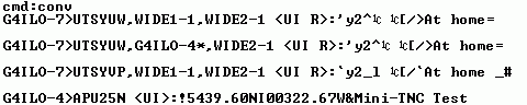
and this is the output from the PIC TNC:

As you can see, the only difference (apart from the fact that the PIC TNC is displaying the packets as it digipeated them while the Kenwood heard both the original and the digipeated versions) is the text UI or UI R in angle brackets before the colon that marks the start of the payload part of the packet. It doesn’t look like something significant enough to make UI-View ignore the packet. It isn’t something that appears in the raw packets listings at aprs.fi. I don’t know what it means or how to generate it in the output from my TNC. So I’m stumped at the moment and am hoping that someone who knows the answer will read this and point me in the direction of a solution.
PIC16F88 TNC
I have mentioned before that when I’m not in the shack I like to run a little program called aprsg to gate all the local APRS activity to a UHF frequency so I can see what is going on in the local APRS world using an APRS-capable HT. I have set up a system using sound card software, a USB sound device and my FT-817ND to do this. But I would like to make a standalone box for this. The first step in this project is to find a simple, cheap TNC.
There are products that would fit the bill from Byonics and Argent Data. Unfortunately they are not available in the UK and the cost of importing these kits from the US makes them less than cheap. I looked at the Fox Delta Mini TNC. But that is not a KISS TNC, as was confirmed by an email to Dinesh, the proprietor of Fox Delta.
Whilst searching around for possible solutions I came across a design for a TNC using a PIC16F88 microcontroller by WB8WGA that was originally published several years ago as an article in the ARRL experimenter magazine QEX. It has been modified by DJ7OO and ZL3AME, who had developed a stripboard layout for it. I had all the bits apart from the microcontroller and the clock crystal, which were quickly sourced on eBay. So I thought it would be an interesting project to build and experiment with.
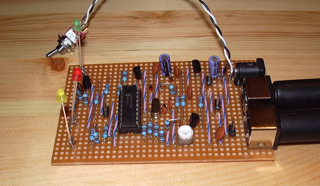
ZL3AME’s stripboard layout results in some quite lengthy signal paths. Despite this, the TNC worked first time, with just a minor glitch caused by my mis-wiring the PTT connection on the transceiver connector. (I have a standardized interface that I use on all my projects, with an 8-pin mini-DIN connector for audio and PTT to the transceiver, and a 6-pin mini-DIN connector for serial and GPS connections. I can then have a standard set of cables to hook the projects up to any radio, connect to the computer or a GPS, etc.)
With all the bits of APRS kit I have it was easy to generate some test signals and I soon had packets being decoded on the terminal screen. I wondered how sensitive the TNC would be as it uses the PIC16F88 to do the decoding instead of a modem chip like the MX614. I have not seen any DX packets decoded yet, but it does seem that decoding success is dependent on the audio level into the TNC. All of my APRS generators were decoded with the exception of my weather station, which has rather low deviation. When using the old Kenwood TH-205E as a receiver I could increase the volume so the weather station was decoded, at the expense of reliable decoding of the other radios. That was not even an option when using the DATA output of a radio, which has a fixed level. I suspect that performance could be improved if you could add an audio ALC on the input.
The TNC can also send APRS beacons and work as a fill-in digipeater. To send a fixed position you can simply encode the position co-ordinates into the beacon text. There are also a couple of jumpers that allow you to connect a GPS to the serial port, which would allow the TNC to work as a standalone tracker. I haven’t tried that, since I already have a standalone tracker. There are no Connect or Disconnect commands so it cannot be used as it stands for packet radio.
This is not a KISS TNC, so it can’t be used with APRSIS32 or aprsg or any of the software I use. I installed UI-View which apparently has the ability to use a TNC for APRS in Converse mode, but it doesn’t work with that either. I think that is due to the fact that the TNC expects CR/LF at the end of each command instead of just CR, so fixing that will be the task of my first attempt at modifying the firmware. Other things I would like to try are making it work at 300baud (for HF packet) instead of 1200baud, and implementing KISS mode. In KISS mode the PC software provides the complete packet and the TNC just has to add a CRC and send it. So in theory it should be simpler to implement than the existing code which has to construct an AX.25 packet from the information entered plus parameters previously set in the configuration. We shall see. The TNC source code is written in assembler, and trying to understand assembler code is to me like not being able to see the wood for the trees. But it will be a good incentive for me to look “under the hood” at how APRS, packet and AX.25 really work.
Many of the links to original information about this project seem now to be dead and I had to do quite a lot of searching to collect the information I have. For the benefit of anyone else who would like to try building one of these TNCs I have assembled all the files and information I found into a zip file which you can download here.
F and C confusion
A few days ago I got the urge to build a memory keyer into my MFJ Cub. There isn’t much of a practical reason for doing this as the noise level on 20m makes the band unusable without the MFJ Noise Canceler which is plumbed into my K3 and too much hassle to disconnect and use with anything else. But I thought it would be a fun thing to do.

I really wanted to use the SKC keyer that is in the DC20B transceiver as it has some nice features and is easy to use. It uses an Atmel ATTiny13 microcontroller. I happened to have a spare one in my parts box and I had managed to find a way to program it using a PICkit2 programmer designed for Microchip parts. Unfortunately my unorthodox programmer always fails trying to read the contents of the chip so I was unable to copy the code from the chip in the DC20B to my spare chip. Nor could I find a source or hex file for the SKC keyer or indeed any other keyer using an ATTiny13 chip. So I had to give that idea up.
I did find a couple of source files for Microchip PIC based keyers on K1EL’s website so I decided I would have to go with that. A couple of years ago I had bought a MikroElektronika EasyPIC5 development system with the intention of experimenting with microchips. Unfortunately I found PIC programming too difficult so I gave up. However I could compile the K1EL keyer code and use the EasyPIC5 to program it into a chip, which I could then build into a keyer that would go in the Cub. Perhaps I could even understand enough of the code to modify it to work the way I wanted.
My first problem was compiling the code. The compiler seemed to object to a label called CONFIG in the source code which caused a fatal error. Eventually I had a lightbulb moment that perhaps CONFIG was a reserved word in the current version of the MPLAB compiler, so I changed the label and the reference to it to CONF. That overcame that problem.
The other problem was that numerous lines in the program produced a message 306, “Crossing page boundary – ensure page bits are set.” I didn’t have a clue what that meant, and although Google turned up a few pages that mentioned the message I didn’t understand what I was supposed to do about it.
The keyer code on K1EL’s website was written for the PIC12C509A chip so I had ordered a couple from PIC Projects on eBay. They arrived in the post this morning. That was when I discovered the second problem. The EasyPIC5 development board does not support PIC12C509A chips. In fact, it doesn’t support any PICs that have C in the number, only ones that have F. It appears that the F chips have Flash memory and can be reprogrammed while the C chips can only be programmed once. So I have two 12C509A chips I can’t use.
I have now ordered some 12F509 chips which are supposed to be compatible with the 12C509 and which my programmer is supposed to be able to program. In a few days time I will discover if that is true and whether message 306 means anything important.
Bricked chip
Last night I received an email from Steve G0XAR to let me know that a replacement chip for the QRSS beacon had been programmed but not posted yet as he had been ill with a bad cold. However my impatience had got the better of me and I started wondering whether I could reprogram the chip myself. Perhaps this was the opportunity I needed to start playing with microcontrollers? The source code was on Hans G0UPL’s website, the development tools were all free. All I would need is a programmer, and I was sure I had seen circuits for microcontroller programmers knocked up from junk box parts on the web.
A bit of searching revealed that simple programmers for the AVR ATtiny13 chip can easily be made, such as this one built by Alan, VK2ZAY, but they require a parallel port, an antique piece of hardware that went out of use around the time Bill Gates made his first billion and is now as obsolete as the USB port will one day surely be.
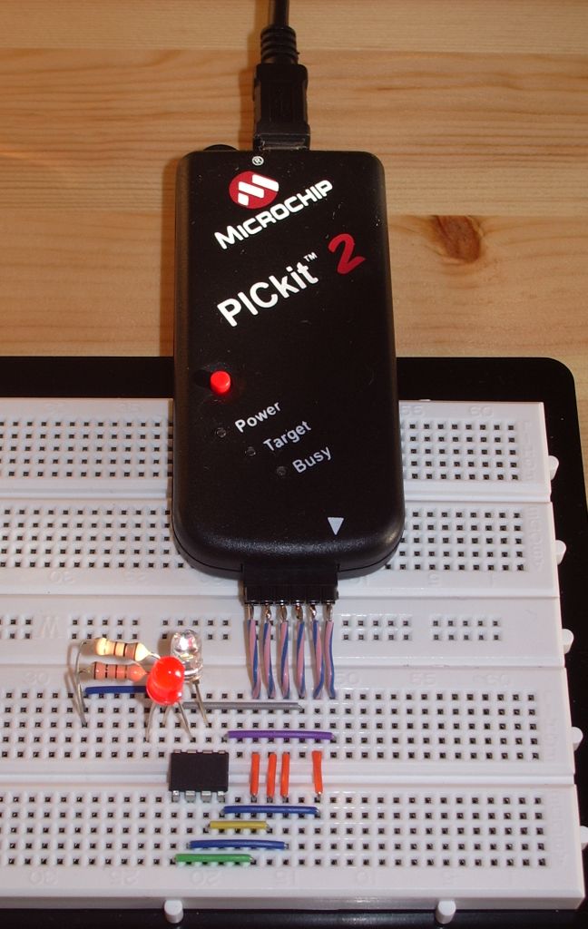
However I also came across an article that described how to program AVR microcontrollers using a Microchip PICkit2 programmer. A couple of years ago I obtained a PICkit2 because it was being offered in an electronics magazine for just the cost of the postage. Apart from running a couple of demo programs I had never done anything with it. What more of an excuse did I need?
In less than an hour I had downloaded and installed the AVR Studio software, WinAVR which was also needed, PK2AVRISP (the program which makes the PICkit2 look like an AVRISP or STK500 programmer), soldered six short leads to a 6-way header to attach to the PICkit2 and wired up the connections to the chip on my solderless breadboard. I already had a pair of virtual serial ports set up on the shack PC to use with the TrueTTY packet TNC so I was good to go.
PK2AVRISP detected my PICkit2 and I assigned it to one of the pair of virtual serial ports. The QRSS keyer program compiled in a couple of seconds and I was ready to program the chip. I selected the AVRISP programmer on the other end of the virtual serial port pair. The programmer read the signature from the chip and reported it was correct – an encouraging sign. Then I wrote the hex code into the flash memory. The write appeared to work but the verification failed with “WARNING: FLASH byte address 0×0006 is 0xFF (should be 0xCF).”
I searched forums for solutions to this error and tried various suggestions such as reducing the SPI clock speed or trying the STK500 option but I could not get past this error. One person claimed that he had somehow managed to program the chip despite the error so I put it back in the QRSS keyer, but now I just got a steady carrier with no keying at all. Oh dear!
I tried programming the code again this time using the avrdude command line programming software which is included with WinAVR but can’t be run directly from AVR Studio. This appeared to work, no error was displayed when the code was verified, but the chip still did not work when put back in the keyer.
To avoid moving the chip back and forth to test it after each programming attempt I tried programming a simple LED flasher into it so I could test it on the breadboard (hence the LEDs in the photo.) This works fine if I simply ignore the flash verification error. So the chip isn’t bricked. But why the keyer program doesn’t work is a mystery. I assume it should flash the LED on pin 3 in time with the keying, but it doesn’t.
Obviously a new chip will get the QRSS keyer working again but having spent all this time on trying to do it myself I would like to know why I couldn’t. Usually when something doesn’t work it is because I have made a stupid error, but I can’t see what I have done wrong. It’s so frustrating.